EP2090728A2 - Dispositif de libération, en particulier pour une porte de véhicule automobile - Google Patents
Dispositif de libération, en particulier pour une porte de véhicule automobile Download PDFInfo
- Publication number
- EP2090728A2 EP2090728A2 EP09001950A EP09001950A EP2090728A2 EP 2090728 A2 EP2090728 A2 EP 2090728A2 EP 09001950 A EP09001950 A EP 09001950A EP 09001950 A EP09001950 A EP 09001950A EP 2090728 A2 EP2090728 A2 EP 2090728A2
- Authority
- EP
- European Patent Office
- Prior art keywords
- base body
- button
- tubular portion
- door
- axial
- Prior art date
- Legal status (The legal status is an assumption and is not a legal conclusion. Google has not performed a legal analysis and makes no representation as to the accuracy of the status listed.)
- Withdrawn
Links
Images

Classifications
-
- E—FIXED CONSTRUCTIONS
- E05—LOCKS; KEYS; WINDOW OR DOOR FITTINGS; SAFES
- E05B—LOCKS; ACCESSORIES THEREFOR; HANDCUFFS
- E05B81/00—Power-actuated vehicle locks
- E05B81/54—Electrical circuits
- E05B81/64—Monitoring or sensing, e.g. by using switches or sensors
- E05B81/76—Detection of handle operation; Detection of a user approaching a handle; Electrical switching actions performed by door handles
-
- E—FIXED CONSTRUCTIONS
- E05—LOCKS; KEYS; WINDOW OR DOOR FITTINGS; SAFES
- E05B—LOCKS; ACCESSORIES THEREFOR; HANDCUFFS
- E05B79/00—Mounting or connecting vehicle locks or parts thereof
- E05B79/02—Mounting of vehicle locks or parts thereof
- E05B79/06—Mounting of handles, e.g. to the wing or to the lock
-
- E—FIXED CONSTRUCTIONS
- E05—LOCKS; KEYS; WINDOW OR DOOR FITTINGS; SAFES
- E05B—LOCKS; ACCESSORIES THEREFOR; HANDCUFFS
- E05B83/00—Vehicle locks specially adapted for particular types of wing or vehicle
- E05B83/16—Locks for luggage compartments, car boot lids or car bonnets
- E05B83/24—Locks for luggage compartments, car boot lids or car bonnets for car bonnets
Definitions
- the present invention refers to a release device which can be used in particular to unlock a motor vehicle door.
- door indicates any body panel that can be opened, such as, for example, a trunk door or a hatchback door of a car.
- the main object of the invention is to made a release device provided with a simple structure and which is adapted to be operated by a user in a simple and comfortable manner.
- the device of the invention is characterized by a simple structure which allows its assembly on the motor vehicle door to be made easier as a result of few simple steps, so as to make it inexpensive both to be manufactured and installed, and which allows to be operated in a practical and quick manner by a user.
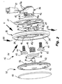
- a motor vehicle 10 comprises a door that can be opened, consisting of a body panel 12 adapted to reach a closed configuration or an open configuration, which correspond to a lowered position and to a raised position (outlined in figure 1 ), respectively, in the case of the trunk or hatchback door of the motor vehicle 10.
- a locking unit of a type known per se (not shown in the figures) that, in the more general case, comprises a movable pawl adapted to engage a seat formed in the body in a position adjacent to the edge of the door 12. Releasing of the locking unit is controlled by a button 14 of a release device 16 associated with the panel 12, which button 14 can be operated by applying a pressure through a finger of a user.
- the release device 16 comprises a base body 18, for example having a circular shape as shown in the figures, which includes a flat plate portion 19 intended to be applied in a frontal bearing on the outer face of the panel 12, with interposition of a seal 21.
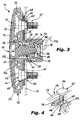
- the appendage 22 includes a tubular portion 24 coaxial with the body 18, which has a transverse bottom wall 26 provided with an axial hole 28, as well as a bracket 25 adjacent to the portion 24.
- the hole 28 is crossed by an end portion 38 of a cylindrical member 30 which extends axially from a plate portion 13, for example disc shaped, of the button 14, facing the body 18.
- a shaped cover member 15 is applied on the outer face of the button 14, which member preferably bears a symbol, such as a trademark, of the motor vehicle 10.
- the button 14 is mounted axially movable with respect to the body 18 and to its portion 24, and is biased towards a direction of removal with respect to the flat portion 19 of the body 18.
- a helical thrust spring 46 is interposed between the bottom 26 of the tubular portion 24 and a radial shoulder 44 of the cylindrical member 30, on the side of the disc portion 13 of the button 14.
- An O-ring seal 47 is arranged between a coaxial collar 47a of the button 14 and another coaxial collar 47b, of a greater diameter, of the body 18, the collar 47b constituting an axial extension of the tubular portion 24, which extends towards the button 14.
- a circular groove 48 is formed close to the free end 38 of the element 30, in which groove a snap ring 50 is inserted, a washer 51 being interposed between the snap ring 50 and the bottom wall 26.
- a plurality of axial pins 52 each of which is adapted to engage a corresponding hole 54 of the flat portion 19 of the body 18, extend from the disc portion 13 of the button 14 towards the body 18.
- Each pin 52 comprises a fork shaped head 56 including a pair of parallel and elastically deformable branches, each of which has a stop tooth 58 on its radially outer surface.
- the diameter of the holes 54 is smaller than the diameter of the head 56 in its undeformed condition, in such a manner that the insertion of the pins 52 in the respectiver holes 54 causes a radial contraction of the branches of the heads 56, which reach again the undeformed condition after having crossed the narrow zone constituted by the edge of the hole 54, so that the pins 52 constitute a pawl stop for the button 14 with respect to the body 18, with the aim of preventig the accidental removal thereof.
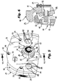
- Connection means which are intended to removably fasten a switch unit 36, are arranged on the outer wall 32 of the end of the tubular portion 24 opposite to the button 14.
- the unit 36 is defined by a cup shaped case which supports an electrical micro-switch 39 connected by a pair of conductors 37a to a female electrical connector 37 of a type known per se, which is adapted to receive a complementary male connector (not shown) with the aim of connecting the unit 36 to a driving electric motor for driving the aforesaid locking unit.
- the micro-switch 39 in the assembled condition of the unit 36, is arranged so that it face frontally the free end 38 of the cylindrical member 30 of the button 14, in order that an axial movement of the button 14 brings the end 38 into contact with the micro-switch 39 to close the electric control circuit for driving the locking unit.
- connection means which include a plurality of tooth formations 34, three with reference to the figures, to allow fastening of the switch unit 36 on the body 18, which formations project radially from the wall 32 and are adapted to be snap engaged into corresponding seats 40 formed in the case of the switch unit 36, as a result of the axial insertion of the switch unit 36 on the tubular portion 24.
- Each seat 40 is delimited by a U shaped edge portion 42, spaced from the reminder of the case of the unit 36 by a pair of axial notches, in such a manner that the edge portions 42 can be pulled apart elastically as a result of the insertion of the body 36, in order to allow the teeth 40 to be engaged in the respective seats 42.
- a pair of bolts are provided to allow fastening of the base body 18 on the panel 12, each of which comprises a screw 60 and a respective check nut 61 that can be engaged on the stem of a screw 60 on the side of the panel 12 opposite to the base body 18.
- the head 62 of each screw 60 has a non-circular shape, for example a square shape, and is received in a seat 64 having a corresponding shape and made in the base body 18.
- a through hole 66 opens in each seat 64 to allow insertion of the stem of a respective screw 60, the circular edge of which being provided with a series of projections 68 intended to interfere with the stem of the screw 60 during the insertion thereof, in order to hold it in the axial direction by friction.
- An eccentric centering formation 70 projects also from the surface of the base body 18 which faces the panel 12, for example having a cross shaped cross-section, which is intended to engage a corresponding seat formed in the panel 12 in a position adjacent to the opening 20.
- the assembly of the device 16 takes place in the following manner. Firstly, the screws 60 are inserted in the holes 66 until their heads 62 engages the seats 64, the deformation of the projections 68 of the holes 66 which results from insertion of the screws 60 being such as to generate a friction allowing the screws 60 to be held in place.
- the button 14 which consists of the disc portion 13 and the cover member 15 already assembled beforehand, is associated with the base body 18 by arranging the O-ring 47 and the spring 46 between them, the latter being arranged inside the tubular portion 24 and in abutment on its bottom wall 26. Insertion of the button 14 into the body 18 ends when the end portion 38 of the cylindrical member 30 projects from the hole 28 of the wall 26. In this condition, the pins 52 are penetrated in the respective holes 54 of the body 18, after their heads 56 have undergone a radial contraction as a result of crossing the holes 54, and are gone back in their undeformed condition.
- the pins 52 carry out a holding action of the button 14 with respect to the base body 18, as a result of the interference of the teeth 58 with the edges of the respective holes 54.
- the washer 51 and the snap ring 50 are then mounted on the free end of the element 30 projecting from the hole 28.
- the unit formed by the button 14 and the base body 18 are therefore associated with the panel 12, by interposing the seal 21 between them, in such a manner that the tubular portion 24 and the bracket formation 25 of the appendage 22 of the body 18 are inserted in the opening 20, the centering formation 70 being arranged so as to engage the respective seat in the panel 12.
- the switch unit 36 is inserted axially in the part of the tubular portion 24 projecting from the internal surface of the panel 12, until the snap engagement of the tooth formations 34 in the seats 40 of the case of the unit 36 is accomplished, as a result of the temporary deformation of the edge portions 42, the insertion of the unit 36 being guided by the sliding engagement of the axial slot 43a of the unit 36 along the tilted ramp 43.
- the check nut 61 can be screwed on the stems of the screws 60 in order to lock the device 16 from inside the panel 12, after that the female connector 37 can be coupled with the respective male connector.
- a pressure applied by a finger of a user on the button 14 causes the movement of the cylindrical member 30 with respect to the base body 18 against the elastic action of the spring 46, as well as the contact of the end 38 of the member 30 with the micro-switch 39, in order close the electric circuit for releasing the locking unit, so that opening of the panel 12 is made possible.
Landscapes
- Lock And Its Accessories (AREA)
- Power-Operated Mechanisms For Wings (AREA)
Applications Claiming Priority (1)
| Application Number | Priority Date | Filing Date | Title |
|---|---|---|---|
| IT000122A ITTO20080122A1 (it) | 2008-02-18 | 2008-02-18 | Dispositivo di sblocco, particolarmente di un portello di un autoveicolo. |
Publications (2)
| Publication Number | Publication Date |
|---|---|
| EP2090728A2 true EP2090728A2 (fr) | 2009-08-19 |
| EP2090728A3 EP2090728A3 (fr) | 2013-06-05 |
Family
ID=40291997
Family Applications (1)
| Application Number | Title | Priority Date | Filing Date |
|---|---|---|---|
| EP09001950.6A Withdrawn EP2090728A3 (fr) | 2008-02-18 | 2009-02-12 | Dispositif de libération, en particulier pour une porte de véhicule automobile |
Country Status (4)
| Country | Link |
|---|---|
| EP (1) | EP2090728A3 (fr) |
| CN (1) | CN101514602B (fr) |
| BR (1) | BRPI0900282A2 (fr) |
| IT (1) | ITTO20080122A1 (fr) |
Cited By (4)
| Publication number | Priority date | Publication date | Assignee | Title |
|---|---|---|---|---|
| US8129639B2 (en) * | 2008-11-13 | 2012-03-06 | Kia Motors Corporation | Emblem-unified trunk opening and closing device |
| DE102011008989A1 (de) * | 2011-01-20 | 2012-07-26 | Gm Global Technology Operations, Llc | Schaltervorrichtung |
| US20180044951A1 (en) * | 2015-03-18 | 2018-02-15 | Illinois Tool Works Inc. | Single axis adjustment feature for flush door handles |
| US12065861B2 (en) | 2019-06-06 | 2024-08-20 | Aisin Corporation | Vehicle door handle device |
Family Cites Families (8)
| Publication number | Priority date | Publication date | Assignee | Title |
|---|---|---|---|---|
| US5308943A (en) * | 1992-12-28 | 1994-05-03 | Otis Elevator Company | Convertible hybrid touch button switch |
| CN2230337Y (zh) * | 1995-05-17 | 1996-07-03 | 张家港星港电子有限公司 | 一种汽车锁具的联锁装置 |
| IT1319905B1 (it) * | 2000-02-23 | 2003-11-12 | Valeo Sicurezza Abitacolo Spa | Maniglia per una portiera di un veicolo. |
| JP3907403B2 (ja) * | 2000-12-06 | 2007-04-18 | ナイルス株式会社 | 防水スイッチ |
| DE50309375D1 (de) * | 2002-07-30 | 2008-04-24 | Huf Huelsbeck & Fuerst Gmbh | Verschluss für mobilteil einer fahrzeugkarosserie, wie einer klappe oder tür, insbesondere für eine heckklappe |
| EP1579097B1 (fr) * | 2002-12-23 | 2010-10-13 | Valeo Sistemas De Seguridad Y De Cierre, S.A. | Commutateur presentant des moyens de retour elastique pour portes ou coffres de vehicules |
| BRMU8402906U (pt) * | 2004-11-30 | 2006-07-11 | Valeo Sistemas Automotivos | aperfeiçoamento construtivo introduzido em sistema de fecho anti-furto aplicado em porta-malas de veìculos automotores |
| JP4702682B2 (ja) * | 2005-07-20 | 2011-06-15 | 株式会社 ユーシン・ショウワ | サムタ−ン装置 |
-
2008
- 2008-02-18 IT IT000122A patent/ITTO20080122A1/it unknown
-
2009
- 2009-02-12 EP EP09001950.6A patent/EP2090728A3/fr not_active Withdrawn
- 2009-02-17 CN CN2009100067655A patent/CN101514602B/zh not_active Expired - Fee Related
- 2009-02-17 BR BRPI0900282-0A patent/BRPI0900282A2/pt not_active Application Discontinuation
Cited By (7)
| Publication number | Priority date | Publication date | Assignee | Title |
|---|---|---|---|---|
| US8129639B2 (en) * | 2008-11-13 | 2012-03-06 | Kia Motors Corporation | Emblem-unified trunk opening and closing device |
| DE102011008989A1 (de) * | 2011-01-20 | 2012-07-26 | Gm Global Technology Operations, Llc | Schaltervorrichtung |
| US8916788B2 (en) | 2011-01-20 | 2014-12-23 | GM Global Technology Operations LLC | Switch device |
| US20180044951A1 (en) * | 2015-03-18 | 2018-02-15 | Illinois Tool Works Inc. | Single axis adjustment feature for flush door handles |
| US10876327B2 (en) * | 2015-03-18 | 2020-12-29 | Illinois Tool Works Inc. | Single axis adjustment feature for flush door handles |
| US11913262B2 (en) | 2015-03-18 | 2024-02-27 | Illinois Tool Works Inc. | Single axis adjustment feature for flush door handles |
| US12065861B2 (en) | 2019-06-06 | 2024-08-20 | Aisin Corporation | Vehicle door handle device |
Also Published As
| Publication number | Publication date |
|---|---|
| CN101514602B (zh) | 2013-04-24 |
| ITTO20080122A1 (it) | 2009-08-19 |
| CN101514602A (zh) | 2009-08-26 |
| EP2090728A3 (fr) | 2013-06-05 |
| BRPI0900282A2 (pt) | 2009-12-01 |
Similar Documents
| Publication | Publication Date | Title |
|---|---|---|
| US8193462B2 (en) | Push button switch for a vehicle door panel | |
| US10954702B2 (en) | Leveled opening control | |
| CN107810303B (zh) | 门闩系统 | |
| EP2820212B1 (fr) | Dispositif d'actionnement | |
| CN103395365B (zh) | 用于车辆的燃料加注管开口的盖结构 | |
| US20130219976A1 (en) | Locking Mechanism | |
| EP2090728A2 (fr) | Dispositif de libération, en particulier pour une porte de véhicule automobile | |
| CN103291131A (zh) | 动力闭锁-解锁装置 | |
| CN211115282U (zh) | 汽车门锁用自吸合驱动机构 | |
| CN108312913B (zh) | 一种改进的儿童安全座椅使用的isofix连接器 | |
| CN108060832B (zh) | 锁具和锁具的紧急解锁方法 | |
| JP6404305B2 (ja) | スライドドア装置 | |
| CN105960498A (zh) | 用于车辆的门把手系统 | |
| US11325487B2 (en) | Electric connection device for electric or hybrid motor vehicles | |
| DE202009001975U1 (de) | Sitzverankerungselement für Kindersicherheitssitze oder Babyträger | |
| CN201633580U (zh) | 头枕导套和使用该头枕导套的座椅 | |
| EP3083339B1 (fr) | Serrure electronique pour une voiture | |
| JP2010127058A (ja) | 車輌用ドア開閉装置 | |
| US9435137B2 (en) | Device for securing an essential component of a motor vehicle handle | |
| CN108625698B (zh) | 具有可移除罩盖的锁定组件 | |
| KR101283477B1 (ko) | 실린더형 전자식 잠금장치용 실린더 몸체 | |
| US20230340804A1 (en) | Compression latch | |
| CN110499970A (zh) | 门锁离合控制系统及汽车 | |
| CN114846210B (zh) | 机动车锁 | |
| CN215418457U (zh) | 一种紧固装置、电池组件及车辆 |
Legal Events
| Date | Code | Title | Description |
|---|---|---|---|
| PUAI | Public reference made under article 153(3) epc to a published international application that has entered the european phase |
Free format text: ORIGINAL CODE: 0009012 |
|
| AK | Designated contracting states |
Kind code of ref document: A2 Designated state(s): AT BE BG CH CY CZ DE DK EE ES FI FR GB GR HR HU IE IS IT LI LT LU LV MC MK MT NL NO PL PT RO SE SI SK TR |
|
| AX | Request for extension of the european patent |
Extension state: AL BA RS |
|
| PUAL | Search report despatched |
Free format text: ORIGINAL CODE: 0009013 |
|
| AK | Designated contracting states |
Kind code of ref document: A3 Designated state(s): AT BE BG CH CY CZ DE DK EE ES FI FR GB GR HR HU IE IS IT LI LT LU LV MC MK MT NL NO PL PT RO SE SI SK TR |
|
| AX | Request for extension of the european patent |
Extension state: AL BA RS |
|
| RIC1 | Information provided on ipc code assigned before grant |
Ipc: E05B 1/00 20060101ALI20130426BHEP Ipc: E05B 17/22 20060101ALI20130426BHEP Ipc: E05B 65/12 20060101AFI20130426BHEP |
|
| AKY | No designation fees paid | ||
| REG | Reference to a national code |
Ref country code: DE Ref legal event code: R108 |
|
| REG | Reference to a national code |
Ref country code: DE Ref legal event code: R108 Effective date: 20140212 |
|
| STAA | Information on the status of an ep patent application or granted ep patent |
Free format text: STATUS: THE APPLICATION IS DEEMED TO BE WITHDRAWN |
|
| 18D | Application deemed to be withdrawn |
Effective date: 20131206 |