EP2090741A1 - Ausdauer von Bohrlochwerkzeugen - Google Patents
Ausdauer von Bohrlochwerkzeugen Download PDFInfo
- Publication number
- EP2090741A1 EP2090741A1 EP08305025A EP08305025A EP2090741A1 EP 2090741 A1 EP2090741 A1 EP 2090741A1 EP 08305025 A EP08305025 A EP 08305025A EP 08305025 A EP08305025 A EP 08305025A EP 2090741 A1 EP2090741 A1 EP 2090741A1
- Authority
- EP
- European Patent Office
- Prior art keywords
- coating
- tool
- corrosion
- friction
- downhole
- Prior art date
- Legal status (The legal status is an assumption and is not a legal conclusion. Google has not performed a legal analysis and makes no representation as to the accuracy of the status listed.)
- Withdrawn
Links
Images


Classifications
-
- E—FIXED CONSTRUCTIONS
- E21—EARTH OR ROCK DRILLING; MINING
- E21B—EARTH OR ROCK DRILLING; OBTAINING OIL, GAS, WATER, SOLUBLE OR MELTABLE MATERIALS OR A SLURRY OF MINERALS FROM WELLS
- E21B17/00—Drilling rods or pipes; Flexible drill strings; Kellies; Drill collars; Sucker rods; Cables; Casings; Tubings
- E21B17/10—Wear protectors; Centralising devices, e.g. stabilisers
- E21B17/1085—Wear protectors; Blast joints; Hard facing
-
- E—FIXED CONSTRUCTIONS
- E21—EARTH OR ROCK DRILLING; MINING
- E21B—EARTH OR ROCK DRILLING; OBTAINING OIL, GAS, WATER, SOLUBLE OR MELTABLE MATERIALS OR A SLURRY OF MINERALS FROM WELLS
- E21B17/00—Drilling rods or pipes; Flexible drill strings; Kellies; Drill collars; Sucker rods; Cables; Casings; Tubings
- E21B17/10—Wear protectors; Centralising devices, e.g. stabilisers
- E21B17/1057—Centralising devices with rollers or with a relatively rotating sleeve
- E21B17/1064—Pipes or rods with a relatively rotating sleeve
Definitions
- the present invention relates to a downhole apparatus and in particular, but not exclusively, to a downhole tool having a suitable coating.
- Downhole tools in the oil industry typically consist of metallic parts that are often moving and chafing against one another or the borehole wall or the mud/hydrocarbon fluid mix passing through or alongside the surfaces of such downhole tools. As a result corrosion occurs.
- Such downhole tools can take on various forms including drill collars, Logging While Drilling (LWD) tools, imaging tools having electrode pads, etc.
- Corrosion control is particularly cost-effective for deep or remote wells, those expected to have a long lifetime or for wells producing carbon dioxide CO2 or hydrogen sulfide H2S.
- Corrosion can be reduced by reduced corrosion resistant metals, but manufacturing the drilling tool parts out of such materials can be costly and precludes existing tools. It is also possible to protect against certain type of corrosion by introducing chemical inhibitors into the mud/hydrocarbon fluid, but this requires a delivery system to inject the chemical inhibitors and also time for the chemical processes to occur.
- an apparatus for downhole operation comprising: a body having a surface located in a borehole; a coating on an at least a portion of the surface of the body, wherein the coating is an inert material selected for reducing friction.
- the advantage of using a coating of an inert material is that not only is corrosion reduced for a downhole tool, but friction is also reduced, which is especially beneficially for moving surfaces.
- a further advantage of the inert coating is that a thinner coat can be applied to the surface of the tool, while still improving the friction and corrosion as compared to other previously used materials.
- a thinner coating is also advantageous in that costs can be reduced, since the material volume is lower, while still extending the life of the downhole equipment.
- the inert material is selected for reducing both friction and corrosion.
- the inert material is at least one of a Diamond Carbon (DC) and a Diamond-like Carbon (DLC) film.
- DC Diamond Carbon
- DLC Diamond-like Carbon
- a second body of the tool having an inert coating on at least a portion of the surface of the second body such that when the inert coating of the body comes into contact with the inert coating of the second body, the friction is considerably reduced.
- a method for reducing friction on a downhole tool comprising: depositing a coating of an inert material on the surface of the downhole tool; and operating the tool within the borehole with reduced friction.
- a further advantage of the coating applied to downhole tools also means that legacy equipment can be equipped with such a coating and upgraded to improve the tool's operating life, rather then being discarded. Yet a further advantage of such coatings is the enhancement of the wear resistance as well as corrosion resistance of the tool, which further extends the lifetime of the tools.
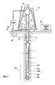
- Figure. 1 illustrates a wellsite system in which the present invention can be employed.
- the invention is concerned with downhole apparatus of all kinds, i.e. the apparatus dealing with drilling tools, measurement tools, logging tools, etc.
- downhole apparatus of all kinds, i.e. the apparatus dealing with drilling tools, measurement tools, logging tools, etc.
- such tools operate in a downhole environment where there is a lot of debris against the surfaces of the tool.
- the coating extends the lifetime and maneuverability of these tools by coating surfaces of the tools with a material which reduced friction and corrosion.
- the exemplary wellsite shown in Figure 1 can be onshore or offshore.
- a borehole 11 is formed in subsurface formations by rotary drilling in a manner that is well known.
- Embodiments of the invention can also use directional drilling, as will be described hereinafter.
- a drill string 12 is suspended within the borehole 11 and has a bottom hole assembly 100 which includes a drill bit 105 at its lower end.
- the surface system includes platform and derrick assembly 10 positioned over the borehole 11, the assembly 10 including a rotary table 16, kelly 17, hook 18 and rotary swivel 19.
- the drill string 12 is rotated by the rotary table 16, energized by means not shown, which engages the kelly 17 at the upper end of the drill string.
- the drill string 12 is suspended from a hook 18, attached to a traveling block (also not shown), through the kelly 17 and a rotary swivel 19 which permits rotation of the drill string relative to the hook.
- a top drive system could alternatively be used.
- the surface system further includes drilling fluid or mud 26 stored in a pit 27 formed at the well site.
- a pump 29 delivers the drilling fluid 26 to the interior of the drill string 12 via a port in the swivel 19, causing the drilling fluid to flow downwardly through the drill string 12 as indicated by the directional arrow 8.
- the drilling fluid exits the drill string 12 via ports in the drill bit 105, and then circulates upwardly through the annulus region between the outside of the drill string and the wall of the borehole, as indicated by the directional arrows 9.
- the drilling fluid lubricates the drill bit 105 and carries formation cuttings up to the surface as it is returned to the pit 27 for recirculation.
- the bottom hole assembly 100 of the illustrated embodiment a logging-while-drilling (LWD) module 120, a measuring-while-drilling (MWD) module 130, a roto-steerable system and motor, and drill bit 105.
- the LWD module 120 is housed in a special type of drill collar, as is known in the art, and can contain one or a plurality of known types of logging tools. It will also be understood that more than one LWD and/or MWD module can be employed, e.g. as represented at 120A. (References, throughout, to a module at the position of 120 can alternatively mean a module at the position of 120A as well.)
- the LWD module includes capabilities for measuring, processing, and storing information, as well as for communicating with the surface equipment.
- the MWD module 130 is also housed in a special type of drill collar, as is known in the art, and can contain one or more devices for measuring characteristics of the drill string and drill bit.
- the MWD tool further includes an apparatus (not shown) for generating electrical power to the downhole system. This may typically include a mud turbine generator powered by the flow of the drilling fluid, it being understood that other power and/or battery systems may be employed.
- the MWD module includes one or more of the following types of measuring devices: a weight-on-bit measuring device, a torque measuring device, a vibration measuring device, a shock measuring device, a stick slip measuring device, a direction measuring device, and an inclination measuring device.
- the effects of corrosion of downhole tools are reduced by applying a protecting coating.
- the protective coating being selected from an inert material and applied to a surface of at least a section of the tool such that is able to mitigate against the effects of corrosion.
- An inert material is a material that does not react with the environment under borehole conditions and prevents corrosion of the substrate in typical well environments.
- coatings made from various inert materials exhibit anti-corrosive properties, but more importantly also exhibit low friction coefficient properties that would be especially useful in the field of downhole tools where there are moving parts and/or fluids.
- DC and DLC films Two inert materials that showed best results for coatings of downhole were the DC and DLC films. That is, these coating exhibit ideal properties of interest for tribology, the science of interactive surfaces in relative motion (friction, wear, lubrication and contact mechanics).
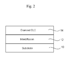
- Figure 2 shows a DLC coating 14 applied to a substrate 10. It should be appreciated that the substrate is likely to be the metal surface of the downhole tool to which the coating is to be applied. Also, Figure 1 shows an interface layer 12 representing the chemical process that bonds the DLC coating 6 to the underlying substrate 2.
- deposition techniques are possible for coating the substrate.
- One form of deposition is where a so-called 'thin' film of between 1-50 ⁇ m directly deposited on the final substrate.
- An alternative form pertains to so-called 'thick' films of between 200 ⁇ m-2mm obtained through a three-stage deposition process: i) deposition on an optimum substrate (copper, silicon, etc), ii) elimination of the substrate and iii) brazing the thick film on the final substrate.
- the interface layer 12 between the substrate 10 and coating 14 is typically a metallic layer deposited via (CVD or PVD - Chemical Vapor Deposition or Physical Vapor Deposition), which typically has a linear thermal expansion coefficient to suppress the scaling effects of the harder diamond layer 14.
- a metallic layer deposited via CVD or PVD - Chemical Vapor Deposition or Physical Vapor Deposition
- the intermediate layer 12 enhances the adherence of the Diamond or DLC layer 14 to the substrate 10.
- the intermediate layer 12 is preferably composed of one layer, but in other embodiments could also be a succession of layers with decreasing linear thermal coefficients.
- a DC film was used, which is an inert material composed of carbon atoms whose hybridization is sp 3 (which is a way of expressing the bonding of the atoms in which each atom allows four neighboring carbons inside a tetrahedral site). Its crystalline structure is of a blend type (cubic base) with the lattice parameter equal to 0.354 nm. Its mechanical, optical, electronic and thermal properties are exceptional (it is both an electrical insulator and a excellent thermal drain). Table 1 shown below gives its principal properties of interest for tribology. DC film properties are compared with best in class materials for hardness and thermal conductivity.
- a DLC film which is also an inert material.
- This material is constituted of carbon atoms whose hybridization is sp 3 (diamond) or sp 2 (graphite). Due to the presence of Csp 3 , this material is hard (3000-4000Hv).
- Two forms can be distinguished, depending on the Csp 3 /Csp 2 ratio and the amount of hydrogen: i) a-C:H where the hydrogen percentage is close to 50% and ii) a-C where the hydrogen percentage is lower, and where the carbon atoms are mainly of the sp 2 hybrid type.
- Diamond-like carbon is a meta-stable amorphous material characterized by attractive optical, electrical, chemical, and tribological properties.
- DLC films can be prepared at low temperatures (as low as 180 deg-C) from a large variety of precursors, and can be modified by the incorporation of different elements such as N (Nickel), F ( Fluorine), Si (Silicon), or metals.
- the films are characterized by infrared transparency, a significant optical gap, high electrical resistivity, low dielectric constant, high hardness and internal compressive stresses, low friction coefficients, and chemical inertness.
- the DLC coatings can improve significantly the anti-corrosion properties of the material used to manufacture critical parts of the logging tools likely to be affected by corrosion, or to prevent galling and seizing in the case of contact between two metal pieces.
- the inert protective coating not only prevents corrosion of the sensitive parts of logging tools, but furthermore reduces friction both between metallic parts of the downhole tool and/or between the downhole tool and the formation itself.
- the friction coefficient of natural diamond is approximately three times lower than that of deposited diamond.
- the value in air is close to 0.1, the value in vacuum can reach 1.0. This difference is due to the presence of adsorbed species and hydrogen as the ending of the emerging bonds in the first case, i.e. air.
- Cavidur is hard amorphous carbon coating (DLC) obtained through a PA-CVD process (deposition temperature: 160-350°C) which was used in testing.
- DLC hard amorphous carbon coating
- Figure 3 shows a LWD (Logging While Drilling) application for reducing corrosion and friction effects of LWD collars which is a common and widespread problem associated with LWD applications.
- LWD Logging While Drilling
- the increasing number of directional and horizontal wells with the combination of rotating stresses, bending stresses and corrosion results in premature loss of the LWD collars.
- DC or DLC coatings increases the life of the LWD collars.
- drill collar for Measurement While Drilling (MWD) applications are equally suitable.
- Figure 4 shows a further application in which the coating can be used to protect small parts of a logging tool. This is particularly useful, for example, in protecting O-rings while operating in sliding mode
- Figure 5 shows yet a further application in which the coating can be applied to rotating shafts where the seal is performed by O-rings.
- the o-ring/shaft seal can be improved by the reduction of the friction coefficient and the reduction of the associated wear.
- Figure 6 shows yet a further application in which the coating is applied to a pads of an imaging tool.
- the pad comprises an array of electrodes, but with the coatings, the surface friction between the pads and adjacent formation is reduced. That is, a widespread problem with imaging tools is that the pad of said tool is found to stick against the formation wall of the borehole. When the imaging tool is trying to be moved, the pad sticks to the wall resulting in a so-called "yo-yo" effect on the tool, which affects the image.
- a further advantage of application of the coating to the imaging tool is to reduce the yo-yo effect and hence improve the quality of the acquired image.
- the imaging tool could be an frequency based imaging tool, for example an FMI tool, but it should be appreciated that other imaging tools are also applicable.
- PVD-CVD coatings such as TiN, TiCN, TiA1N,WC/C, etc.
Landscapes
- Engineering & Computer Science (AREA)
- Life Sciences & Earth Sciences (AREA)
- Geology (AREA)
- Mining & Mineral Resources (AREA)
- Mechanical Engineering (AREA)
- Physics & Mathematics (AREA)
- Environmental & Geological Engineering (AREA)
- Fluid Mechanics (AREA)
- General Life Sciences & Earth Sciences (AREA)
- Geochemistry & Mineralogy (AREA)
- Earth Drilling (AREA)
- Piles And Underground Anchors (AREA)
Priority Applications (3)
| Application Number | Priority Date | Filing Date | Title |
|---|---|---|---|
| EP08305025A EP2090741A1 (de) | 2008-02-15 | 2008-02-15 | Ausdauer von Bohrlochwerkzeugen |
| US12/867,313 US8631864B2 (en) | 2008-02-15 | 2009-02-06 | Durability of downhole tools |
| PCT/IB2009/000241 WO2009101507A2 (en) | 2008-02-15 | 2009-02-06 | Durability of downhole tools |
Applications Claiming Priority (1)
| Application Number | Priority Date | Filing Date | Title |
|---|---|---|---|
| EP08305025A EP2090741A1 (de) | 2008-02-15 | 2008-02-15 | Ausdauer von Bohrlochwerkzeugen |
Publications (1)
| Publication Number | Publication Date |
|---|---|
| EP2090741A1 true EP2090741A1 (de) | 2009-08-19 |
Family
ID=39638661
Family Applications (1)
| Application Number | Title | Priority Date | Filing Date |
|---|---|---|---|
| EP08305025A Withdrawn EP2090741A1 (de) | 2008-02-15 | 2008-02-15 | Ausdauer von Bohrlochwerkzeugen |
Country Status (3)
| Country | Link |
|---|---|
| US (1) | US8631864B2 (de) |
| EP (1) | EP2090741A1 (de) |
| WO (1) | WO2009101507A2 (de) |
Cited By (7)
| Publication number | Priority date | Publication date | Assignee | Title |
|---|---|---|---|---|
| US8220563B2 (en) | 2008-08-20 | 2012-07-17 | Exxonmobil Research And Engineering Company | Ultra-low friction coatings for drill stem assemblies |
| WO2012116036A2 (en) | 2011-02-22 | 2012-08-30 | Exxonmobil Research And Engineering Company | Coated sleeved oil gas well production devices |
| US8261841B2 (en) | 2009-02-17 | 2012-09-11 | Exxonmobil Research And Engineering Company | Coated oil and gas well production devices |
| WO2012122337A2 (en) | 2011-03-08 | 2012-09-13 | Exxonmobil Research And Engineering Company | Altra-low friction coatings for drill stem assemblies |
| WO2012135306A2 (en) | 2011-03-30 | 2012-10-04 | Exxonmobil Research And Engineering Company | Coated oil and gas well production devices |
| US8286715B2 (en) | 2008-08-20 | 2012-10-16 | Exxonmobil Research And Engineering Company | Coated sleeved oil and gas well production devices |
| US20250084735A1 (en) * | 2022-03-07 | 2025-03-13 | Schlumberger Technology Corporation | Carbon rich layer for scale control |
Families Citing this family (6)
| Publication number | Priority date | Publication date | Assignee | Title |
|---|---|---|---|---|
| WO2013039485A1 (en) * | 2011-09-13 | 2013-03-21 | Halliburton Energy Services, Inc. | Measuring an adsorbing chemical in downhole fluids |
| US9404334B2 (en) | 2012-08-31 | 2016-08-02 | Baker Hughes Incorporated | Downhole elastomeric components including barrier coatings |
| US11053740B2 (en) | 2014-12-30 | 2021-07-06 | Halliburton Energy Services, Inc. | Downhole tool surfaces configured to reduce drag forces and erosion during exposure to fluid flow |
| US9989665B2 (en) * | 2015-04-29 | 2018-06-05 | Schlumberger Technology Corporation | Wear resistant electrodes for downhole imaging |
| US20170275950A1 (en) * | 2016-03-22 | 2017-09-28 | Baker Hughes Incorporated | Downhole tools having volumes of hard material including quenched carbon and related methods |
| US20180201826A1 (en) * | 2017-01-17 | 2018-07-19 | Baker Hughes, A Ge Company, Llc | Synergistic corrosion inhibitors |
Citations (5)
| Publication number | Priority date | Publication date | Assignee | Title |
|---|---|---|---|---|
| US20020041930A1 (en) * | 1998-04-20 | 2002-04-11 | Ali Erdemir | Method to produce ultra-low friction carbon films |
| US6450271B1 (en) * | 2000-07-21 | 2002-09-17 | Baker Hughes Incorporated | Surface modifications for rotary drill bits |
| US20040031624A1 (en) * | 2002-08-19 | 2004-02-19 | Scott Danny E. | DLC coating for earth-boring bit seal ring |
| EP1788104A1 (de) * | 2005-11-22 | 2007-05-23 | MEC Holding GmbH | Werkstoff für Teile oder Beschichtungen, die Verschleiss oder Reibung ausgesetzt sind, Verfahren zu deren Herstellung und Verwendung des Werkstoffes in einer Vorrichtung zur Drehmomentreduzierung bei Bohrstrangkomponenten |
| WO2007091054A1 (en) * | 2006-02-08 | 2007-08-16 | Thomas John Oliver Thornton | Improvements in and relating to downhole tools |
Family Cites Families (5)
| Publication number | Priority date | Publication date | Assignee | Title |
|---|---|---|---|---|
| US4783995A (en) * | 1987-03-06 | 1988-11-15 | Oilfield Service Corporation Of America | Logging tool |
| US6942043B2 (en) * | 2003-06-16 | 2005-09-13 | Baker Hughes Incorporated | Modular design for LWD/MWD collars |
| US7385401B2 (en) * | 2005-07-08 | 2008-06-10 | Baker Hughes Incorporated | High resolution resistivity earth imager |
| US7600419B2 (en) * | 2006-12-08 | 2009-10-13 | Schlumberger Technology Corporation | Wellbore production tool and method |
| US20080236842A1 (en) * | 2007-03-27 | 2008-10-02 | Schlumberger Technology Corporation | Downhole oilfield apparatus comprising a diamond-like carbon coating and methods of use |
-
2008
- 2008-02-15 EP EP08305025A patent/EP2090741A1/de not_active Withdrawn
-
2009
- 2009-02-06 US US12/867,313 patent/US8631864B2/en not_active Expired - Fee Related
- 2009-02-06 WO PCT/IB2009/000241 patent/WO2009101507A2/en not_active Ceased
Patent Citations (5)
| Publication number | Priority date | Publication date | Assignee | Title |
|---|---|---|---|---|
| US20020041930A1 (en) * | 1998-04-20 | 2002-04-11 | Ali Erdemir | Method to produce ultra-low friction carbon films |
| US6450271B1 (en) * | 2000-07-21 | 2002-09-17 | Baker Hughes Incorporated | Surface modifications for rotary drill bits |
| US20040031624A1 (en) * | 2002-08-19 | 2004-02-19 | Scott Danny E. | DLC coating for earth-boring bit seal ring |
| EP1788104A1 (de) * | 2005-11-22 | 2007-05-23 | MEC Holding GmbH | Werkstoff für Teile oder Beschichtungen, die Verschleiss oder Reibung ausgesetzt sind, Verfahren zu deren Herstellung und Verwendung des Werkstoffes in einer Vorrichtung zur Drehmomentreduzierung bei Bohrstrangkomponenten |
| WO2007091054A1 (en) * | 2006-02-08 | 2007-08-16 | Thomas John Oliver Thornton | Improvements in and relating to downhole tools |
Cited By (9)
| Publication number | Priority date | Publication date | Assignee | Title |
|---|---|---|---|---|
| US8220563B2 (en) | 2008-08-20 | 2012-07-17 | Exxonmobil Research And Engineering Company | Ultra-low friction coatings for drill stem assemblies |
| US8286715B2 (en) | 2008-08-20 | 2012-10-16 | Exxonmobil Research And Engineering Company | Coated sleeved oil and gas well production devices |
| EP2326790B1 (de) * | 2008-08-20 | 2018-11-21 | Exxonmobil Upstream Research Company | Beschichtungen für meisselstangenanordnungen mit ultraniedriger reibung |
| US8261841B2 (en) | 2009-02-17 | 2012-09-11 | Exxonmobil Research And Engineering Company | Coated oil and gas well production devices |
| WO2012116036A2 (en) | 2011-02-22 | 2012-08-30 | Exxonmobil Research And Engineering Company | Coated sleeved oil gas well production devices |
| WO2012122337A2 (en) | 2011-03-08 | 2012-09-13 | Exxonmobil Research And Engineering Company | Altra-low friction coatings for drill stem assemblies |
| WO2012135306A2 (en) | 2011-03-30 | 2012-10-04 | Exxonmobil Research And Engineering Company | Coated oil and gas well production devices |
| US20250084735A1 (en) * | 2022-03-07 | 2025-03-13 | Schlumberger Technology Corporation | Carbon rich layer for scale control |
| US12448870B2 (en) * | 2022-03-07 | 2025-10-21 | Schlumberger Technology Corporation | Carbon rich layer for scale control |
Also Published As
| Publication number | Publication date |
|---|---|
| WO2009101507A3 (en) | 2010-09-30 |
| US8631864B2 (en) | 2014-01-21 |
| WO2009101507A2 (en) | 2009-08-20 |
| US20110061945A1 (en) | 2011-03-17 |
Similar Documents
| Publication | Publication Date | Title |
|---|---|---|
| US8631864B2 (en) | Durability of downhole tools | |
| EP2326790B1 (de) | Beschichtungen für meisselstangenanordnungen mit ultraniedriger reibung | |
| EP2938754B1 (de) | Beschichtungen mit geringer reibung und verbesserten abrieb- und verschleisseigenschaften sowie verfahren zur herstellung | |
| EP2398994B1 (de) | Beschichtete öl- und gasbohrungsfördervorrichtungen | |
| EP2539622B1 (de) | Beschichtete ummantelte fördervorrichtung für öl- und gasbohrlöchern | |
| US20140173995A1 (en) | Methods of making a drilling tool with low friction coatings to reduce balling and friction | |
| US20110042069A1 (en) | Coated sleeved oil and gas well production devices | |
| WO2012122337A2 (en) | Altra-low friction coatings for drill stem assemblies | |
| WO2012135306A2 (en) | Coated oil and gas well production devices | |
| US9790608B2 (en) | Methods of forming borided down hole tools | |
| US20130014995A1 (en) | Downhole Motor with Diamond-Like Carbon Coating on Stator and/or Rotor | |
| US11364705B2 (en) | Diamond-like-carbon based friction reducing tapes | |
| AU2009283227B2 (en) | Ultra-low friction coatings for drill stem assemblies | |
| CN106062300B (zh) | 用于井筒形成的低表面摩擦钻头主体 |
Legal Events
| Date | Code | Title | Description |
|---|---|---|---|
| PUAI | Public reference made under article 153(3) epc to a published international application that has entered the european phase |
Free format text: ORIGINAL CODE: 0009012 |
|
| AK | Designated contracting states |
Kind code of ref document: A1 Designated state(s): AT BE BG CH CY CZ DE DK EE ES FI FR GB GR HR HU IE IS IT LI LT LU LV MC MT NL NO PL PT RO SE SI SK TR |
|
| AX | Request for extension of the european patent |
Extension state: AL BA MK RS |
|
| 17P | Request for examination filed |
Effective date: 20100206 |
|
| 17Q | First examination report despatched |
Effective date: 20100331 |
|
| AKX | Designation fees paid | ||
| REG | Reference to a national code |
Ref country code: DE Ref legal event code: 8566 |
|
| STAA | Information on the status of an ep patent application or granted ep patent |
Free format text: STATUS: THE APPLICATION IS DEEMED TO BE WITHDRAWN |
|
| 18D | Application deemed to be withdrawn |
Effective date: 20100220 |