EP2090743B1 - Dispositif de coque - Google Patents
Dispositif de coque Download PDFInfo
- Publication number
- EP2090743B1 EP2090743B1 EP09152831A EP09152831A EP2090743B1 EP 2090743 B1 EP2090743 B1 EP 2090743B1 EP 09152831 A EP09152831 A EP 09152831A EP 09152831 A EP09152831 A EP 09152831A EP 2090743 B1 EP2090743 B1 EP 2090743B1
- Authority
- EP
- European Patent Office
- Prior art keywords
- formwork
- tunnel
- elements
- window
- standardized
- Prior art date
- Legal status (The legal status is an assumption and is not a legal conclusion. Google has not performed a legal analysis and makes no representation as to the accuracy of the status listed.)
- Not-in-force
Links
- 238000009415 formwork Methods 0.000 title claims abstract description 361
- 238000010276 construction Methods 0.000 claims description 9
- 238000006073 displacement reaction Methods 0.000 claims description 4
- 230000015572 biosynthetic process Effects 0.000 abstract description 3
- 238000012986 modification Methods 0.000 abstract 1
- 230000004048 modification Effects 0.000 abstract 1
- 239000010410 layer Substances 0.000 description 52
- 238000009416 shuttering Methods 0.000 description 35
- 229910000831 Steel Inorganic materials 0.000 description 8
- 239000010959 steel Substances 0.000 description 8
- 229920001084 poly(chloroprene) Polymers 0.000 description 5
- 239000000463 material Substances 0.000 description 4
- 238000005096 rolling process Methods 0.000 description 4
- 238000005520 cutting process Methods 0.000 description 3
- 238000005304 joining Methods 0.000 description 2
- 238000004519 manufacturing process Methods 0.000 description 2
- 239000013589 supplement Substances 0.000 description 2
- 230000005641 tunneling Effects 0.000 description 2
- 238000003466 welding Methods 0.000 description 2
- 230000006978 adaptation Effects 0.000 description 1
- 230000000295 complement effect Effects 0.000 description 1
- 239000002131 composite material Substances 0.000 description 1
- 230000006835 compression Effects 0.000 description 1
- 238000007906 compression Methods 0.000 description 1
- 238000007689 inspection Methods 0.000 description 1
- 238000009434 installation Methods 0.000 description 1
- 238000004064 recycling Methods 0.000 description 1
- 239000002356 single layer Substances 0.000 description 1
Images




Classifications
-
- E—FIXED CONSTRUCTIONS
- E21—EARTH OR ROCK DRILLING; MINING
- E21D—SHAFTS; TUNNELS; GALLERIES; LARGE UNDERGROUND CHAMBERS
- E21D11/00—Lining tunnels, galleries or other underground cavities, e.g. large underground chambers; Linings therefor; Making such linings in situ, e.g. by assembling
- E21D11/04—Lining with building materials
- E21D11/10—Lining with building materials with concrete cast in situ; Shuttering also lost shutterings, e.g. made of blocks, of metal plates or other equipment adapted therefor
- E21D11/102—Removable shuttering; Bearing or supporting devices therefor
Definitions
- the invention relates to a formwork element for a tunnel formwork, a tunnel formwork and a formwork device with such a tunnel formwork for underground tunneling.
- Such formwork devices have a formwork carriage and a tunnel formwork of a plurality of formwork elements joined together.
- the formwork elements are arranged on the formwork carriage and together form the inner formwork for a tunnel section.
- the formwork elements are arranged in layers or longitudinal strip areas on the formwork carriage. These layers of the tunnel formwork extend over the length of the tunnel formwork.
- On both sides of the shuttering cart is ever a side wall formwork available. These side wall formworks are so movably mounted on the shuttering car that they can be brought to the shuttering carriage in a Verfahrwolf and away from the formwork carriage in a concreting position.
- Conventional formwork devices have formwork, which are composed of ring elements.
- a plurality of ring elements is joined together in the longitudinal direction of the formwork.
- the ring form elements form e.g. in a single layer a sidewall formwork.
- the ring formwork element can be composed of several elements.
- a disadvantage of known formwork devices of this type is further that the formwork elements must be built very stable, and yet can only be used once, since rarely two identical tunnel cross-sections must be made. For reasons of competitiveness, formwork manufacturers are forced to take back the formwork elements and use them for another project. However, since hardly any two tunnel sections are identical, the formwork elements must be adapted for the second application. This is done with cutting disc and welding torch in an elaborate work. The resulting cost savings compared to the production of a new formwork is often insufficient.
- Tunnel formwork for the lining of tunnels are generally known from many sources (eg also according to published patent application DE 30 17 057 ). Some of the supports for the formworks are size-adjustable and can be adapted to different tunnel sizes (eg according to the published patent application EP 1 123 650 ).
- the formwork devices are partially equipped with recesses. From the Scriptures JP 2005-002730 inspection windows are known. In document JP 03-891210 Windows are disclosed, which serve to facilitate the construction and dismantling of the scaffold. In the scriptures DT 24 53 281 . CH 437 404 and JP 2007-138594 Tunnel sheathing with lockable recesses are disclosed, which may be used to fill the back room with concrete. CH 437404 may be considered as the closest prior art.
- a formwork device for tunneling with a movable formwork scaffold known wearing formwork elements that extend over the entire length of the tunnel formwork.
- a plurality of identical formwork elements is present, which partially shell the tunnel wall, in part the tunnel ceiling.
- longitudinal joints are formed, which are fed up in the concreting position.
- the formwork elements are flat over the thickness of each other.
- the formwork elements are pivoted to the formwork scaffold, so that the formwork device can be moved within the concrete tunnel tube.
- This formwork is suitable for a specific tunnel cross-section. In the ridge of the formwork, a curved steel plate is placed over the spaced-apart formwork elements. An adaptation of the tunnel cross-section is conceivable only in this area.
- the document makes no statement.
- the formwork element is characterized by the features of independent claim 1, the tunnel formwork by the features of independent claim 7 and the formwork device by the features of independent claim 11.
- the formwork element according to the invention for a tunnel formwork 15 with a formwork surface forming a Schal lakeelement is characterized in that in the formwork element a plurality of window positions 61 is formed, the window positions are identical in terms of their dimensions and at all window positions a constant arrangement of attachment points is present , wherein at the window position a concreting window 61.1 is excluded from the Schalvidelement and a window shutter 61.3 or a concreting 61.2 in the recess of the concreting window 61.1 is interchangeable attached to the attachment points.
- the formwork element is characterized in that over the entire length of the formwork element extending ribs 63 and transverse to the ribs 63 frames 65 for support on a formwork carriage 13 are present, and that the window position 61 is formed by two changes in the ribs 63.
- the formwork element is characterized in that the attachment points are formed on the ribs 63, to which the window shuttering arranged in the concreting window or the concreting section arranged in the concreting window can be fastened.
- the formwork element is characterized in that its along its direction in the formwork longitudinal direction, stretched edge is cantilevered.
- the formwork element is characterized in that the formwork element 31, 31.0, 33 has a normalized element length of advantageously 500 or 1000 cm and a normalized element radius and thereby supplemented for an arrangement in a through a project-specific layer 60 of the tunnel formwork 15, over the length of Tunnel formwork 15 extending standard position 10 is suitable.
- the formwork element is characterized in that the formwork element 31, 31.0, 33 in the circumferential direction of the tunnel formwork 15 have at most a width of 350 cm, preferably of at most 300 cm, particularly preferably of at most 250 cm.
- the inventive tunnel shuttering 15 consisting of a plurality of shuttering elements 31 screwed together and at least one shuttering element, characterized in that between the shuttering elements 91.1, 91.2 in formwork longitudinally stretched joints and in shuttering circumferential direction optionally curved joints are present, and that in the extended joints the Schal lake sculpture 91.1, 91.2 are arranged at a distance between 5 and 15 mm to each other and between the Schalzinianan a compressible belt 99 is clamped, which fills this distance.
- the tunnel shuttering is characterized in that the compressible belt 99 is cut flush with a shuttering surface of the shutter surface elements 91.1, 91.2.
- the tunnel formwork is characterized in that the band 99 is foamed.
- the tunnel shuttering is characterized in that the compressed belt 99 engages behind the shutter surface elements 91.1, 91.2.
- the formwork device is characterized in that at least one layer 10, 60 of the side wall formwork 19, 19 'is a standard layer 10 that has a normalized width in the circumferential direction of the tunnel formwork 15, and that the side wall formwork 19, 19' is adjacent to one of the standard layers 10 project specific situation 60 is added.
- the shuttering device is characterized in that there is a slab formwork 17 which, in particular together with the formwork carriage 13, can be lowered into a displacement position and lifted into a concreting position, which slab formwork 17 has at least two standard layers 10 directed in the longitudinal direction of the tunnel shuttering 15, which in the circumferential direction of the tunnel formwork 15 have a normalized width and the Schal lake longitudinal direction of the tunnel formwork directed elongated joints are freely cantilevered.
- the formwork device is characterized in that the standard layers 10 of the slab formwork 17 comprise at most 3 formwork elements 31, 31.1; 31.0, 31.2; 31, 31.3 per layer 10 are joined, of which formwork elements 31, 31.1; 31.0, 31.2; 31, 31.3 a layer a longitudinal shuttering element 31; 31.0; 31 each occupies more than half the length of the tunnel formwork 15.
- the shuttering device is characterized in that the normalized widths of the standard layers 10 are stepped in at least one step, the width difference between two steps being between 50 and 100 cm, preferably 75 cm.
- a plurality of window locations are formed according to the invention in at least one formwork element of the tunnel formwork.
- window positions can order specific by cutting out the Formwork surface element designed a concreting window and a window formwork or concreting are arranged interchangeable in the concreting window.
- Such a window position is formed by two changes in the ribs. At the window location no opening must be formed. Its purpose is that an opening can be formed with simple means and quickly on site.
- all formwork elements at least as far as they can be referred to as standard formwork elements, formed with such window positions.
- This allows to place a concrete pipe where it proves to be suitable on the construction site.
- the location of the concrete neck can also be changed from stage to stage.
- the concrete nozzle or a window formwork can be easily replaced.
- a formwork device with such a tunnel formwork is characterized in that the side wall formworks are assembled from at least two layers and from at most 3 formwork elements per layer.
- a formwork element is a longitudinal formwork element which occupies at least half the length of the tunnel formwork in each layer.
- the tunnel formwork is therefore no longer divided into ring formwork elements, but rather in relatively narrow longitudinal strip areas or layers.
- the longitudinal formwork element can be supplemented at one end or at both ends with a supplementary formwork element in order to adapt the length of the tunnel formwork to the project-specific required length.
- the division into longitudinal strips with a relatively small width has the advantage that once used layers of formwork elements can be reused, even if the tunnel radius is slightly different.
- the adjacent layers can be assembled in the longitudinal joints with small intermediate angles so as to widen the radius of the tunnel cross-section. Or project-specific intermediate layers between two existing layers of Shuttering elements are inserted to customize the tunnel cross section project specific.
- the length of the reusable formwork elements corresponds to a length that previously had to be used only once, project-specific formwork parts for cams or formwork foot sections.
- the longitudinal formwork element advantageously has a length which often occurs in tunnel construction, and is lengthened if necessary with a supplementary formwork element.
- Reusable formwork elements are advantageously produced in normal dimensions. At least one layer of the side wall formwork is therefore a standard layer which has a normalized width in the circumferential direction of the tunnel formwork. Such a standard situation is then usually supplemented by a project-specific situation adjacent to the standard situation. This project-specific situation need not be produced in the same quality as the standard formwork elements intended for reuse. It extends advantageously over the entire length of the tunnel formwork. Such a supplement may be a layer that defines a pivot axis of the sidewall formwork, or a layer that defines a bend for a ceiling cam or that defines the bottom sidewall end.
- the standard positions of the side wall formwork can be formed by vaulted casings or by flat formwork or, and this is assumed to be the most common case, a layer with vault shell elements and a layer with flat formwork elements.
- the formwork wagon conveniently carries a slab formwork.
- This slab formwork can be lowered, in particular together with the formwork carriage, into a displacement position and raised to a concreting position.
- the slab formwork advantageously has at least two standard layers directed in the longitudinal direction of the tunnel formwork, which have a standardized width in the circumferential direction of the tunnel formwork.
- the construction of the slab formwork of standard formwork elements again has the advantage that the cross section of the tunnel can be designed to be project-specific despite the use of standardized formwork elements.
- the ceiling radius can be to a sufficient extent be adjusted by small angles in the longitudinal joints or by project-specific intermediate formwork elements between two standard positions.
- the configured tunnel cross-section can thus also be maintained with predominantly normalized elements within the tolerances.
- the slab formwork is advantageously supplemented by at least one project-specific layer adjacent to the standard position.
- the standard layers of the slab formwork are expediently assembled from at most 3 formwork elements per layer, of which formwork elements of one layer a longitudinal formwork element occupies more than half the length of the tunnel formwork.
- formwork elements have the advantage that only a few running in the cross-sectional direction joints need to be added project specific and on the formwork element length no such joints are available. This leads to a high precision in the formwork thanks to small inaccuracies in the joints.
- the size of the formwork elements is advantageously limited to a suitable transport size.
- a shuttering element should have in width, which is in the circumferential direction of a standard position of gap to joint at most a dimension of 350 cm.
- Such an element would normally have to be provided for transport. Therefore, a smaller width of at most 300 cm is preferred.
- Formwork elements with a width of at most 250 cm can be easily transported horizontally and are therefore to be preferred.
- the smaller widths are also to be preferred, because with narrower elements of flexible project-specific cross-sections can be produced.
- a preferred grading of standard widths is 250 cm, 175 cm and possibly 125 cm.
- the normalized widths of the standard documents are expediently graduated in one, two or three stages, the difference in width between two stages between 50 and 100 cm, preferably around 75 cm.
- the difference in width is also matched to the ribbed grid, so that the window position details can be the same.
- individual tunnel cross-sections of standard parts and a few project-specific formwork elements can be assembled.
- a longitudinal formwork element is expediently at least 500 cm long in the tunnel longitudinal direction. With 5 meter sections already very small curve radii can shell.
- a preferred length of the longitudinal formwork elements is 10 meters. This length can be supplemented by special parts on, for example, 12 or another project-specific length, but in many cases meets the requirements of curve radii in highway and road construction.
- the formwork elements have excellent rigidity
- the formwork elements are provided with extending over the entire length of the formwork element ribs.
- the supported on the formwork trolleys run transversely to the continuous ribs.
- the longitudinal formwork element expediently has a normalized element length and a normalized element radius.
- a system of longitudinal formwork elements is preferably formed which comprises formwork elements with different radii, different widths and possibly also different lengths. Such a system may have the following components in different numbers.
- the formwork elements can be made to order specific in, for example, these standard sizes, then, if they are needed: Radius (cm) Width (cm) Length (cm) Supplement lengths (cm) 300 about 100 1000/500 125/200/250 300 about 125 1000/500 125/200/250 510 about 125 1000 200/250 510 about 175 1000 200/250 510 about 250 1000 200/250
- radii are preferably around 350, 700 and 900 cm.
- project-specific formwork elements are present in the tunnel formwork whose element width deviates from the normalized element width. These are preferably over the entire length of the tunnel formwork, so made of length element and supplementary element (s).
- Project-specific formwork elements are in particular intended to form project-specific shapes, such as edges, cams, or to achieve project-specific radii or pivot axes.
- a tunnel formwork which, in a known manner, consists of a plurality of shuttering elements bolted together, joints stretched between the shuttering surfaces in the longitudinal direction of the formwork and optionally curved joints in the formwork circumferential direction.
- the object is achieved in that the stretched joints the scarfing surface are arranged at a distance between 5 and 15 mm to each other and between the formwork elements and the scarf surfaces, that is so in this joint, a compressible band is clamped, which fills this distance , This allows to obtain tight joints when the formwork elements with their contact surfaces lie flat on each other, as well as when the formwork elements are pushed together with a wedge-shaped intermediate layer in an angled position.
- the compressible band is inserted over the joint and cut only after the connection of the two formwork elements in a plane of the joint.
- the Schal lake should advantageously survive the joining surfaces of the half-ribs, so that the material of the compressible band can undercut the Schal lake. If the compressed band engages behind the scarf surface, it can not escape from the joint.
- the material band is advantageously made of a foamed material. This allows a large compression range.
- a suitable material for the band is neoprene.
- the invention relates in summary to a formwork element for a tunnel formwork, with a form a Schal structure forming Schal lakeelement in which a plurality of window positions is formed.
- the manner of the formation of the window position allows, at the window position job specific Exclude concreting window from the Schal horrelement, if this is not cut out, and arrange a window formwork or concreting in the recess of the concreting window replaceable.
- the invention also relates to a tunnel formwork with a plurality of formwork elements and at least one formwork element with a plurality of such window locations, as well as a formwork device with a formwork carriage and such a tunnel formwork.
- FIG. 1 illustrated cross-section shows a two-lane road tunnel while concreting a formwork section.
- the shuttering device 11 arranged therein comprises a formwork carriage 13 and a tunnel formwork 15.
- the tunnel formwork 15 is divided into different areas which are differently movable.
- the formwork carriage 13 spans a construction site passage profile.
- the slab formwork 17 is arranged.
- the slab formwork 17 can be lowered together with the formwork carriage.
- the side wall formwork 19, 19 ' also includes a foot end 23, 23', which is pivotable about a second pivot axis 25, 25 'relative to the remaining part of the side wall formwork 19, 19'.
- an individual formwork 18,18 ' which is designed project-specific. It comprises the pivot axes 21,21 'and the cam form 27,27'.
- the cam formwork comprises a cam flap 41, 41 ', which can be pivoted toward the formwork carriage 13 about the pivot axis 21, 21'. Only in this formwork carriage pivoted position of the shuttering car is lowered.
- the slab formwork 17 is formed from three standard positions and two supplementary layers. Each standard position is formed of standard formwork elements 31, which have a formwork width of 250 cm and a radius of 510 cm.
- the supplementary layers connect outside to the standard conditions. They consist of a supplementary element 32,32 ', which is designed project-specific. Here it serves as a connection to the cam flap 41,41 'of the cam form 27,27'.
- the sidewall formwork comprises four layers. At the top is a supplementary layer of a supplementary element 42,42 'is formed.
- the supplementary element 42,42 ' forms the kink between side wall curve and cam and defines the pivot axis 21,21' for the side wall formwork 19,19 '.
- the subsequent upper layer is a standard position and includes a standard formwork element 33 of width 175 cm with the radius 510 cm.
- the adjoining the standard position lower layer comprises a flat formwork element 35 of width 175 cm with a pivot axis 25,25 'for articulating the noirabBankes 23,23'.
- the foldable foot end 23, 23 ' is articulated to the pivot axis 25, 25'.
- the tunnel formwork 15 is a one-sided formwork.
- the pressure of the concrete can therefore not be absorbed by binding together two walls forming a wall on both sides. Rather, the pressure is transmitted from one side wall formwork 19 'to the other side wall formwork 19.
- the pressure of the slab formwork 17 is supported on the tunnel floor 39 via the side wall formworks 19, 19 '.
- the resulting forces are on supports 45,45 ', which are partially adjustable in length 45', passed to a cross member 43.
- the cross member 43 is part of the formwork carriage thirteenth
- FIG. 2 the tunnel formwork is shown in a traversing position.
- the side wall formwork 19,19 'are pivoted to the formwork carriage 13 zoom.
- the formwork carriage 13 is lowered.
- all formwork parts are removed from the wall of the freshly concreted tunnel tube 47, so that the formwork device 11 can be moved on the wheels of the rolling feet 49 via the tunnel bottom 39.
- the formwork can be cleaned in this position.
- At the new position in the tunnel she will return to the in FIG. 1 shown concreting position brought.
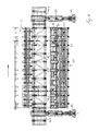
- the formwork carriage 13 is shown without the tunnel formwork.
- the formwork carriage 13 comprises wheels in rolling feet 49.
- the rolling feet 49 are formed transversely to the tunnel direction relative to the lifting legs 51 loading thereon.
- the lifting legs 51 each carry a two in the tunnel longitudinal direction truss 53.53 '.
- the lifting legs 51 are each arranged in the feed direction of the formwork device 11 in front of and behind the tunnel formwork 15 on the truss 53.53 '. Thanks to the height adjustability of the lifting legs 51, the tunnel formwork can be raised for concreting with its apex to the peak height of the tunnel tube and lowered to move by about 70 cm.
- the cross member 43 are also formed as trusses. They have a top flange 44 and a bottom flange 46, and vertical bars 48.
- the length and the height of the cross member 43 are to be dimensioned project specific.
- the cross member is composed of a modular system. This modular system includes cross member bars 40.1, 40.2, 40.3, 40.4 different length.
- the lengths of the cross member bars 40 are formed in a 10 cm grid.
- Each crossbar 40 has the same end plates and the same cross section of the steel profile.
- the steel profile is a practically square H-profile.
- the flanges of the H-profile are perforated in a 10 cm grid.
- each cross member bar 40 can be arranged on the end face of both of these for the extension of another cross member bar 40, and also on a flange of another cross member rod 40 for forming a vertical bar 48. Further, it is possible to insert diagonal bars in the cross member 43. These are formed in the nature of the tunnel formwork 15 supporting columns 45.
- a complementary cross member bar can be made to achieve a cross member length, which is outside the grid.
- the chosen 10 cm grid should be sufficiently small, since the rolling feet 49 are each designed to be displaceable by up to 10 cm.
- the lifting legs 51 are equipped on three sides with mounting flanges. They can therefore be mounted on the front side (and front or rear) or on the outside of the truss girders 53,53 '.
- the trusses have corresponding mounting surfaces. These mounting surfaces and the mounting flanges on the lifting legs 51 are perforated in a 12 cm grid. The perforation allows the lifting legs each to be mounted on a truss-specific height on the truss 53.
- the truss 53 is visible in its longitudinal extent.
- the truss 53 is composed of 4 pieces.
- the basic element 50.1 has a length of 10 meters and is a welded construction.
- An additional truss 50.2 complements the length of the base element 50.1 on the project-specific desired length of the longitudinal truss.
- an end piece 50.3, 50.4 is arranged. This end piece is screwed to the base element 50.1 or to the supplementary truss 50.2.
- Each end piece 50.3, 50.4 is equipped with mounting surfaces for mounting the lifting legs 51.
- perforated flanges are formed on the opposite side of the end piece 50.3, 50.4, on which cross members 43 can be mounted.
- Such flanges for mounting the cross member are also formed on each vertical rod of the truss girder 53.
- the ends of the base element 50.1, the supplementary truss girder 50.2, and the end pieces 50.3 and 50.4 in total are stiffened with sheets and stiffening ribs. Between the vertical bars of the truss girder 53 diagonal bars for stiffening the truss girder 53 are present.
- struts 55 are hooked into the holes of the cross member bars 40 and the required length up or twisted together.
- These struts 55 are formed as clamping elements and have a central part with two opposing internal threads and two end portions with each corresponding external threads. These struts can therefore be used diagonally or orthogonally and serve only as a composite of the support system.
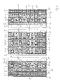
- the tunnel formwork 15 is shown in total. This includes the three areas left side wall formwork 19 ', slab formwork 17 and right side wall formwork 19.
- the left and right side wall formwork are largely mirror-inverted. They differ in the dimensions of the supplementary elements 42,42 'of the uppermost layer. These supplementary elements 42,42 'are integrally formed over the entire length of the tunnel formwork 15. They are project-specific. This is followed by a curved formwork layer consisting of a 10-meter-long standard formwork element 33 and a 2-meter-long supplementary formwork element 33. 1 or the supplementary formwork element 33. Together, the standard formwork element 33 and the supplementary formwork element 33.1 or 33.1 'have the length of the tunnel formwork 15. At the joint 57, the two formwork elements are screwed together. The frames are perforated in a 10 cm grid. All this allows the uncomplicated reuse of the two formwork elements of this standard situation.
- planar formwork element 35, 35 'and the foot flap 23, 23' hinged thereto are a project-specific formwork elements and have the length of the tunnel formwork 15. In the case of a recycling of these elements, they would probably have to be adapted. These elements could also be specifically adapted to the left and right sidewall molds. They are only provided with the necessary for the bracing perforations or with welded bracing feet 59.
- the slab formwork 17 comprises three standard layers of 2.5 meters width. Each standard situation consists of a 10-meter standard formwork element 31 or 31.0 and a 2-meter-long supplementary formwork element 31.1, 31.2 or 31.3.
- the standard formwork elements with a length of 10 meters are distinguished by the arrangement of the concreting window positions 61.
- the concreting window locations 61 are formed in the vertex, while in the laterally arranged these window locations 61 are arranged outside the center.
- the formwork elements have a longitudinal rib structure.
- the ribs 63 extend from one end of the formwork element to the other. These ribs 63 are supported by ribs 65, which are correspondingly arched to the radius of the tunnel cross-section.
- the ribs 65 are arranged at a grid spacing of 125 cm from each other, wherein the shuttering surface projects in each case half a grid spacing over the last ribs 65.
- a concreting window point 61 is formed.
- a concreting window 61.1, a concreting 61.2 or a concreting window form 61.3 can be arranged. Object specific, therefore, the desired opening can be provided in many places.
- window locations 61 are shown larger.
- the ribs 63 are interrupted only in the area of the window locations 61.
- vibrator holders 67 are provided in order to fix it to external vibrators can. These are mounted on bridges between two ribs 63.
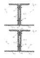
- FIGS. 8 and 9 a horizontal joint between two formwork elements 31 of adjacent layers is shown.
- the Schal lakeelement 91.1, 91.2 is designated from a 10 to 15 mm thick steel sheet with 91.1 or 91.2. These Schal lakeiata are supported by ribs (not shown). These ribs are themselves supported by ribs (not shown). From frame to frame extends along the horizontal joint an L-section steel 93.1, 93.2, which carries the edge of the Schal lakeelements 91.1, 91.2. The two steel sections 93.1, 93.2 are bolted together by means of screws at points 95.
- pressure surfaces on the L-profiles are doubled at the points 95, which can be ground precisely. In the FIG. 8 illustrated situation in which the pressure surfaces abut each other directly and planar, is therefore the normal case at a radius corresponding to the element radius tunnel.
- the tunnel radius is required to be 530 cm, but the existing elements have a radius of 510 cm, the larger radius can still be shunted with the existing elements.
- the scarf surfaces 91.1 and 91.2 then run no longer precisely planar or barrel-shaped in one another, but form a formwork kink. However, this is within the tolerances when the formwork elements 31 are relatively narrow, so that there are many horizontal joints.
- the steel profiles 93.1 and 93.2 are at a distance from the edge of the Schalvidelements 91.1, or 91.2 welded to this, so that the longitudinal edge of the Schalvidelements 91.1 and 91.2 is freely cantilevered.
- the gap between the shuttering elements 31 is further than between the shutter surface elements behind the shutter surface elements.
- the neoprene band 99 also fills this further space and thereby undercuts the Schalvidiata 91.1, 91.2. This ensures that the neoprene tape 99 can not be removed from the joint, except by loosening the two assembled formwork elements 31st
- joint seal can also be selected in joints that run in the circumferential direction, or in horizontal joints that lie at joints. In the latter, the two adjacent formwork elements opposite to the representation in FIGS. 8 and 9 not screwed together.
Landscapes
- Engineering & Computer Science (AREA)
- Architecture (AREA)
- Structural Engineering (AREA)
- Mining & Mineral Resources (AREA)
- Civil Engineering (AREA)
- Life Sciences & Earth Sciences (AREA)
- General Life Sciences & Earth Sciences (AREA)
- Geochemistry & Mineralogy (AREA)
- Geology (AREA)
- Lining And Supports For Tunnels (AREA)
- Forms Removed On Construction Sites Or Auxiliary Members Thereof (AREA)
Claims (15)
- Elément de coffrage pour un coffrage de tunnel (15) avec un élément de surface de coffrage formant une surface de coffrage, une multitude d'emplacements de fenêtres (61) étant configurée dans l'élément de coffrage, caractérisé en ce que les emplacements de fenêtre sont identiques pour ce qui est de leurs dimensions et qu'il existe un arrangement constant de points de fixation pour tous les emplacements de fenêtre, une fenêtre de bétonnage (61.1) étant évidéedans l'élément de surface de coffrage à l'emplacement de fenêtre et un coffrage de fenêtre (61.3) ou un ajutage de bétonnage (61.2) étant fixé en étant remplaçable dans l'évidement de la fenêtre de bétonnage (61.1) aux endroits de fixation.
- Elément de coffrage selon la revendication 1, caractérisé en ce qu'il existe des nervures (63) sur toute la longueur de l'élément de coffrage et qu'il existe des renforts (65) transversalement aux nervures (63) pour l'étaiement sur un chariot de coffrage (13) et que l'emplacement de fenêtre (61) est formé par deux chevêtres dans les nervures (63).
- Elément de coffrage selon la revendication 2, caractérisé en ce que les endroits de fixation sont configurés sur les nervures (63).
- Elément de coffrage selon l'une des revendications 1 à 3, caractérisé en ce que le bord de celui-ci qui est étiré et orienté dans le sens longitudinal du coffrage est configuré en porte-à-faux.
- Elément de coffrage selon l'une des revendications 1 à 4, caractérisé en ce que l'élément de coffrage (31, 31.0, 33) présente une longueur d'élément normalisée d'avantageusement 500 ou 1000 cm et un rayon d'élément normalisé et est donc approprié pour un arrangement dans une couche normalisée (10) qui est complétée par une couche spécifique au projet (60) ducoffrage de tunnel (15)et qui s'étend sur la longueur du coffrage du tunnel (15).
- Elément de coffrage selon la revendication 6, caractérisé en ce que l'élément de coffrage (31, 31.0, 33) présente, dans le sens de la circonférence du coffrage de tunnel (15), une largeur maximale de 350 cm, de préférence de 300 cm maximum, de manière particulièrement préférée de 250 cm maximum.
- Coffrage de tunnel (15) constitué par une multitude d'éléments de coffrage vissés les uns aux autres (31) et par au moins un élément de coffrage selon l'une des revendications 1 à 6, caractérisé en ce qu'il existe des joints étirés dans le sens longitudinal du coffrage entre les éléments de surfaces de coffrage (91.1, 91.2) du coffrage de tunnel et des joints éventuellement courbés dans le sens circonférentiel du coffrage et que les éléments de surfaces de coffrage (91.1, 91.2) sont placés pour les joints étirés en étant espacés entre 5 et 15 mm et qu'une bande compressible (99), qui remplit cet espace, est coïncée entre les éléments de surfaces de coffrage.
- Coffrage de tunnel selon la revendication 7, caractérisé en ce que la bande compressible (99) est coupée en affleurement avec une surface supérieure des éléments de surfaces de coffrage (91.1, 91.2).
- Coffrage de tunnel selon la revendication 7, caractérisé en ce que la bande (99) est expansée.
- Coffrage de tunnel selon l'une des revendications 7 à 9, caractérisé en ce que la bande compressible (99) saisit les éléments de surfaces de coffrage (91.1, 91.2) par derrière.
- Dispositif de coffrage pour la construction souterraine de tubes de tunnel (47) en béton comprenant
un chariot de coffrage (13) et
un coffrage de tunnel (15) avec une multitude d'éléments de coffrage (23, 23', 27, 27', 31, 31.0, 31.1, 31.2, 31.3, 33, 33.1, 33.1', 35, 35', 41, 41', 42, 42') et au moins un élément de coffrage selon l'une des revendications 1 à 6, caractérisé en ce que les éléments de coffrage (23, 23', 27, 27', 31, 31.0, 31.1, 31.2, 31.3, 33, 33.1, 33.1', 35, 35', 41, 41', 42, 42')- sont assemblés les uns aux autres avec des éléments de surfaces de coffrage (91.1, 91.2),- sont placés en couches (10, 60) sur le chariot de coffrage (13), lesquelles couches (10, 60) s'étendent sur la longueur du coffrage de tunnel (15),- un coffrage de paroi latérale (19, 19') existant sur chacun des deux côtés du chariot de coffrage (13), lesquels coffrages de paroi latérale (19, 19') sont montés mobiles de telle manière qu'ils peuvent être amenés dans une position de déplacement vers le chariot de coffrage (13) et qu'ils peuvent être amenés dans une position de bétonnageen s'éloignant du chariot de coffrage (13)et que les coffrages de paroi latérale (19, 19') sont assemblés à partir d'au moins deux couches (10, 60) et d'au plus 3 éléments de coffrage (33, 33.1 ; 33, 33.1') par couche (10, 60), éléments de coffrage (23, 23', 27, 27', 31, 31.0, 31.1, 31.2, 31.3, 33, 33.1, 33.1', 35, 35', 41, 41', 42, 42') d'une couche (10, 60) dont au moins l'un est un élément de coffrage longitudinal (23, 23', 27, 27', 31, 31.0, 33, 35, 35', 41, 41', 42, 42') qui occupe au moins la moitié de la longueur du coffrage de tunnel (15). - Dispositif de coffrage selon la revendication 11, caractérisé en ce qu'au moins une couche (10, 60) du coffrage de paroi latérale (19, 19') est une couche normalisée (10) qui a, dans le sens de la circonférence du coffrage de tunnel (15), une largeur normalisée et que le coffrage de paroi latérale (19, 19') est complété par une couche spécifique au projet (60) voisine de la couche normalisée (10).
- Dispositif de coffrage selon la revendication 11 ou 12, caractérisé en ce qu'il existe un coffrage de dessus (17) qui peut être abaissé dans une position de déplacement, en particulier avec le chariot de coffrage (13), et qui peut être levé dans une position de bétonnage, lequel coffrage de dessus (17) présente au moins deux couches normalisées (10), orientées dans le sens longitudinal du coffrage de tunnel (15), qui présentent une largeur normalisée dans le sens de la circonférence du coffrage de tunnel (15) et dont les éléments de surfacesde coffrage sont configurés en porte-à-faux dans des joints étirés dans le sens longitudinal du coffrage de tunnel.
- Dispositif de coffrage selon la revendication 13, caractérisé en ce que les couches normalisées (10) du coffrage de dessus (17) sont assemblées à partir de 3 éléments de coffrage (31, 31.0, 31.1, 31.2, 31.3) par couche (10), éléments de coffrage (31, 31.0, 31.1, 31.2, 31.3) d'une couche dont un élément de coffrage longitudinal (31 ; 31.0; 31) occupe respectivement plus de la moitié de la longueur du coffrage de tunnel (15).
- Dispositif de coffrage selon l'une des revendications 12 à 14, caractérisé en ce que les largeurs normalisées des couches normalisées (10) sont échelonnées dans au moins un degré, la différence de largeur entre deux degrés étant entre 50 et 100 cm, de préférence de 75 cm.
Applications Claiming Priority (1)
| Application Number | Priority Date | Filing Date | Title |
|---|---|---|---|
| CH00204/08A CH702134B1 (de) | 2008-02-13 | 2008-02-13 | Schalungsvorrichtung. |
Publications (2)
| Publication Number | Publication Date |
|---|---|
| EP2090743A1 EP2090743A1 (fr) | 2009-08-19 |
| EP2090743B1 true EP2090743B1 (fr) | 2011-10-19 |
Family
ID=39735476
Family Applications (1)
| Application Number | Title | Priority Date | Filing Date |
|---|---|---|---|
| EP09152831A Not-in-force EP2090743B1 (fr) | 2008-02-13 | 2009-02-13 | Dispositif de coque |
Country Status (3)
| Country | Link |
|---|---|
| EP (1) | EP2090743B1 (fr) |
| AT (1) | ATE529610T1 (fr) |
| CH (1) | CH702134B1 (fr) |
Families Citing this family (6)
| Publication number | Priority date | Publication date | Assignee | Title |
|---|---|---|---|---|
| CN102650211B (zh) * | 2012-05-22 | 2015-11-25 | 湖南五新隧道智能装备股份有限公司 | 直线及曲线段隧洞通用式钢模衬砌台车 |
| CN106223983A (zh) * | 2016-09-14 | 2016-12-14 | 中国葛洲坝集团第六工程有限公司 | 一种引水隧洞斜井、平段全断面通用钢模台车 |
| CN107060830A (zh) * | 2017-06-09 | 2017-08-18 | 中铁十七局集团第五工程有限公司 | 单线隧道二次衬砌混凝土逐窗浇筑装置及其施工方法 |
| CN111140260B (zh) * | 2020-02-25 | 2025-03-18 | 河南金基业重工有限公司 | 可调承重脚悬架的隧道台车 |
| CN113719300B (zh) * | 2020-10-29 | 2024-05-24 | 怀化市众建机械钢模制造有限公司 | 一种便于支模的隧道台车 |
| CN115573741B (zh) * | 2022-11-03 | 2023-11-10 | 南通路桥工程有限公司 | 通道侧墙及顶板液压模板台车 |
Family Cites Families (14)
| Publication number | Priority date | Publication date | Assignee | Title |
|---|---|---|---|---|
| GB711282A (en) * | 1951-04-24 | 1954-06-30 | W & J R Watson Ltd | Improvements in or relating to shuttering for casting concrete |
| AT251022B (de) | 1964-12-24 | 1966-12-12 | Universale Hoch & Tiefbau | Vorrichtung zum Auskleiden von Tunnelröhren und Stollen mit Pump- oder Spritzbeton |
| DE2453281C3 (de) | 1974-11-09 | 1978-03-16 | Bochumer Eisenhuette Heintzmann Gmbh & Co, 4630 Bochum | Ortsveränderbares Schalungsgerüst |
| DE3017057C2 (de) | 1980-05-03 | 1984-11-22 | Hochtief Ag Vorm. Gebr. Helfmann, 4300 Essen | Anordnung zur Verhinderung des Einbetonierens eines Nachlaufringschwanzes im Ortbetonausbau hinter einer Messervortriebsmaschine |
| FR2752013B1 (fr) * | 1996-07-30 | 1998-10-23 | Parra Robert | Anneau de coffrage courbe |
| FR2756312B1 (fr) * | 1996-11-28 | 1999-01-15 | Parra Robert | Dispositif de coffrage de tunnel |
| ATE318991T1 (de) * | 1999-10-28 | 2006-03-15 | Zueblin Ag | Verfahren zum verschalen von wandungen eines tunnels und schalung zur durchführung des verfahrens |
| EP1123650A1 (fr) | 2000-02-11 | 2001-08-16 | Lin Sproule | Système d'arrosage de plantes |
| IT1320275B1 (it) * | 2000-03-24 | 2003-11-26 | Mecsider S P A | Carro porta-forma a dimensioni regolabili per gallerie. |
| JP4241204B2 (ja) | 2003-06-13 | 2009-03-18 | 株式会社福田組 | トンネル天頂部のコンクリート締め固め方法及び装置 |
| FR2881791B1 (fr) * | 2005-02-08 | 2007-06-01 | Robert Parra | Dispositif et procede d'alimentation d'un volume de confinement pour la realisation d'une paroi de renforcement d'une excavation, sans carotte |
| JP3891210B1 (ja) | 2005-09-27 | 2007-03-14 | 株式会社エムケーエンジニアリング | 内型枠構造 |
| JP4566891B2 (ja) | 2005-11-18 | 2010-10-20 | 株式会社奥村組 | トンネル覆工コンクリート打設方法 |
| FR2895441A1 (fr) * | 2005-12-27 | 2007-06-29 | Robert Parra | Dispositif et procede de coffrage a absorption de poussee, pour tunnel |
-
2008
- 2008-02-13 CH CH00204/08A patent/CH702134B1/de not_active IP Right Cessation
-
2009
- 2009-02-13 EP EP09152831A patent/EP2090743B1/fr not_active Not-in-force
- 2009-02-13 AT AT09152831T patent/ATE529610T1/de active
Also Published As
| Publication number | Publication date |
|---|---|
| ATE529610T1 (de) | 2011-11-15 |
| EP2090743A1 (fr) | 2009-08-19 |
| CH702134B1 (de) | 2011-05-13 |
Similar Documents
| Publication | Publication Date | Title |
|---|---|---|
| EP2090744B1 (fr) | Chariot de transport | |
| EP0182212B1 (fr) | Coffrage pour la réalisation de constructions en matériaux coulés, p.ex. béton | |
| DE3247231C2 (fr) | ||
| EP2090743B1 (fr) | Dispositif de coque | |
| DE102016204633A1 (de) | Deckentisch und Deckenschalung mit einem solchen Deckentisch | |
| EP3572198B1 (fr) | Coffrage central pour un système de coffrage destiné à bétonner un corps de cloche | |
| DE69731886T2 (de) | Schalungssystem | |
| DE10219896C1 (de) | Schalungssystem für Betonkörper | |
| DE102007047919A1 (de) | Traggerüst und Verfahren zur Demontage und Transport | |
| DE2759088A1 (de) | Kletterschalung zur herstellung einer geraden oder gekruemmten stahlbetonwand | |
| DE3836568C2 (de) | Lehrgerüst für Stahlbetonbrücken für universellen Einsatz als stationäres und Verschiebegerüst | |
| AT500952B1 (de) | Gerüstträger aus aluminium | |
| DE2423953C2 (de) | Verfahrbares Schalungsgerät zum Betonieren von Tunnelröhren | |
| AT501248B1 (de) | Vorrichtung zum erstellen von insbesondere viertel-, halb- oder vollgewendelten ortbeton-treppen | |
| WO1984000189A1 (fr) | Procede pour le betonnage de parois et coffrage pour sa mise en oeuvre | |
| EP0857834B1 (fr) | Méthode et échaffaudage pour ériger des murs en béton | |
| EP0231525B1 (fr) | Dispositif de passage pour joints de dilatation dans les tabliers des ponts de chemin de fer | |
| AT412359B (de) | Schalung | |
| DE19536895B4 (de) | Schalung für Betonstützen | |
| DE19834476C1 (de) | Schalung und Verfahren zur Aufstellung | |
| EP0104262A1 (fr) | Dalle mixte autoportante - produit - méthode - dispositif - application | |
| WO2009043748A1 (fr) | Dispositif de coffrage pour une construction en porte-à-faux de pont | |
| DE2559426C2 (de) | Vorrichtung zur Errichtung einer Wand mittels verlorener Schalungsplatten | |
| DE2426126A1 (de) | Vorrichtung fuer den bau von tunnels, stollen usw. mit oder ohne auskleidung | |
| DE29915343U1 (de) | Stahlbetonteil zur Herstellung von Fundamenten für Bauwerke |
Legal Events
| Date | Code | Title | Description |
|---|---|---|---|
| PUAI | Public reference made under article 153(3) epc to a published international application that has entered the european phase |
Free format text: ORIGINAL CODE: 0009012 |
|
| AK | Designated contracting states |
Kind code of ref document: A1 Designated state(s): AT BE BG CH CY CZ DE DK EE ES FI FR GB GR HR HU IE IS IT LI LT LU LV MC MK MT NL NO PL PT RO SE SI SK TR |
|
| AX | Request for extension of the european patent |
Extension state: AL BA RS |
|
| 17P | Request for examination filed |
Effective date: 20100114 |
|
| 17Q | First examination report despatched |
Effective date: 20100211 |
|
| AKX | Designation fees paid |
Designated state(s): AT BE BG CH CY CZ DE DK EE ES FI FR GB GR HR HU IE IS IT LI LT LU LV MC MK MT NL NO PL PT RO SE SI SK TR |
|
| GRAP | Despatch of communication of intention to grant a patent |
Free format text: ORIGINAL CODE: EPIDOSNIGR1 |
|
| GRAS | Grant fee paid |
Free format text: ORIGINAL CODE: EPIDOSNIGR3 |
|
| GRAA | (expected) grant |
Free format text: ORIGINAL CODE: 0009210 |
|
| AK | Designated contracting states |
Kind code of ref document: B1 Designated state(s): AT BE BG CH CY CZ DE DK EE ES FI FR GB GR HR HU IE IS IT LI LT LU LV MC MK MT NL NO PL PT RO SE SI SK TR |
|
| REG | Reference to a national code |
Ref country code: GB Ref legal event code: FG4D Free format text: NOT ENGLISH |
|
| REG | Reference to a national code |
Ref country code: CH Ref legal event code: NV Representative=s name: RIEDERER HASLER & PARTNER PATENTANWAELTE AG Ref country code: CH Ref legal event code: EP |
|
| REG | Reference to a national code |
Ref country code: IE Ref legal event code: FG4D |
|
| REG | Reference to a national code |
Ref country code: DE Ref legal event code: R096 Ref document number: 502009001626 Country of ref document: DE Effective date: 20120119 |
|
| REG | Reference to a national code |
Ref country code: NL Ref legal event code: VDEP Effective date: 20111019 |
|
| LTIE | Lt: invalidation of european patent or patent extension |
Effective date: 20111019 |
|
| PG25 | Lapsed in a contracting state [announced via postgrant information from national office to epo] |
Ref country code: NO Free format text: LAPSE BECAUSE OF FAILURE TO SUBMIT A TRANSLATION OF THE DESCRIPTION OR TO PAY THE FEE WITHIN THE PRESCRIBED TIME-LIMIT Effective date: 20120119 Ref country code: LT Free format text: LAPSE BECAUSE OF FAILURE TO SUBMIT A TRANSLATION OF THE DESCRIPTION OR TO PAY THE FEE WITHIN THE PRESCRIBED TIME-LIMIT Effective date: 20111019 Ref country code: IS Free format text: LAPSE BECAUSE OF FAILURE TO SUBMIT A TRANSLATION OF THE DESCRIPTION OR TO PAY THE FEE WITHIN THE PRESCRIBED TIME-LIMIT Effective date: 20120219 |
|
| REG | Reference to a national code |
Ref country code: IE Ref legal event code: FD4D |
|
| PG25 | Lapsed in a contracting state [announced via postgrant information from national office to epo] |
Ref country code: SI Free format text: LAPSE BECAUSE OF FAILURE TO SUBMIT A TRANSLATION OF THE DESCRIPTION OR TO PAY THE FEE WITHIN THE PRESCRIBED TIME-LIMIT Effective date: 20111019 Ref country code: LV Free format text: LAPSE BECAUSE OF FAILURE TO SUBMIT A TRANSLATION OF THE DESCRIPTION OR TO PAY THE FEE WITHIN THE PRESCRIBED TIME-LIMIT Effective date: 20111019 Ref country code: SE Free format text: LAPSE BECAUSE OF FAILURE TO SUBMIT A TRANSLATION OF THE DESCRIPTION OR TO PAY THE FEE WITHIN THE PRESCRIBED TIME-LIMIT Effective date: 20111019 Ref country code: PT Free format text: LAPSE BECAUSE OF FAILURE TO SUBMIT A TRANSLATION OF THE DESCRIPTION OR TO PAY THE FEE WITHIN THE PRESCRIBED TIME-LIMIT Effective date: 20120220 Ref country code: HR Free format text: LAPSE BECAUSE OF FAILURE TO SUBMIT A TRANSLATION OF THE DESCRIPTION OR TO PAY THE FEE WITHIN THE PRESCRIBED TIME-LIMIT Effective date: 20111019 Ref country code: NL Free format text: LAPSE BECAUSE OF FAILURE TO SUBMIT A TRANSLATION OF THE DESCRIPTION OR TO PAY THE FEE WITHIN THE PRESCRIBED TIME-LIMIT Effective date: 20111019 Ref country code: GR Free format text: LAPSE BECAUSE OF FAILURE TO SUBMIT A TRANSLATION OF THE DESCRIPTION OR TO PAY THE FEE WITHIN THE PRESCRIBED TIME-LIMIT Effective date: 20120120 |
|
| PG25 | Lapsed in a contracting state [announced via postgrant information from national office to epo] |
Ref country code: CY Free format text: LAPSE BECAUSE OF FAILURE TO SUBMIT A TRANSLATION OF THE DESCRIPTION OR TO PAY THE FEE WITHIN THE PRESCRIBED TIME-LIMIT Effective date: 20111019 |
|
| PG25 | Lapsed in a contracting state [announced via postgrant information from national office to epo] |
Ref country code: BG Free format text: LAPSE BECAUSE OF FAILURE TO SUBMIT A TRANSLATION OF THE DESCRIPTION OR TO PAY THE FEE WITHIN THE PRESCRIBED TIME-LIMIT Effective date: 20120119 Ref country code: DK Free format text: LAPSE BECAUSE OF FAILURE TO SUBMIT A TRANSLATION OF THE DESCRIPTION OR TO PAY THE FEE WITHIN THE PRESCRIBED TIME-LIMIT Effective date: 20111019 Ref country code: IE Free format text: LAPSE BECAUSE OF FAILURE TO SUBMIT A TRANSLATION OF THE DESCRIPTION OR TO PAY THE FEE WITHIN THE PRESCRIBED TIME-LIMIT Effective date: 20111019 Ref country code: CZ Free format text: LAPSE BECAUSE OF FAILURE TO SUBMIT A TRANSLATION OF THE DESCRIPTION OR TO PAY THE FEE WITHIN THE PRESCRIBED TIME-LIMIT Effective date: 20111019 Ref country code: EE Free format text: LAPSE BECAUSE OF FAILURE TO SUBMIT A TRANSLATION OF THE DESCRIPTION OR TO PAY THE FEE WITHIN THE PRESCRIBED TIME-LIMIT Effective date: 20111019 Ref country code: SK Free format text: LAPSE BECAUSE OF FAILURE TO SUBMIT A TRANSLATION OF THE DESCRIPTION OR TO PAY THE FEE WITHIN THE PRESCRIBED TIME-LIMIT Effective date: 20111019 |
|
| PLBE | No opposition filed within time limit |
Free format text: ORIGINAL CODE: 0009261 |
|
| STAA | Information on the status of an ep patent application or granted ep patent |
Free format text: STATUS: NO OPPOSITION FILED WITHIN TIME LIMIT |
|
| BERE | Be: lapsed |
Owner name: JORIMANN STAHL A.G. Effective date: 20120228 |
|
| PG25 | Lapsed in a contracting state [announced via postgrant information from national office to epo] |
Ref country code: PL Free format text: LAPSE BECAUSE OF FAILURE TO SUBMIT A TRANSLATION OF THE DESCRIPTION OR TO PAY THE FEE WITHIN THE PRESCRIBED TIME-LIMIT Effective date: 20111019 Ref country code: RO Free format text: LAPSE BECAUSE OF FAILURE TO SUBMIT A TRANSLATION OF THE DESCRIPTION OR TO PAY THE FEE WITHIN THE PRESCRIBED TIME-LIMIT Effective date: 20111019 Ref country code: IT Free format text: LAPSE BECAUSE OF FAILURE TO SUBMIT A TRANSLATION OF THE DESCRIPTION OR TO PAY THE FEE WITHIN THE PRESCRIBED TIME-LIMIT Effective date: 20111019 |
|
| 26N | No opposition filed |
Effective date: 20120720 |
|
| PG25 | Lapsed in a contracting state [announced via postgrant information from national office to epo] |
Ref country code: MC Free format text: LAPSE BECAUSE OF NON-PAYMENT OF DUE FEES Effective date: 20120229 |
|
| REG | Reference to a national code |
Ref country code: DE Ref legal event code: R097 Ref document number: 502009001626 Country of ref document: DE Effective date: 20120720 |
|
| REG | Reference to a national code |
Ref country code: FR Ref legal event code: ST Effective date: 20121031 |
|
| PG25 | Lapsed in a contracting state [announced via postgrant information from national office to epo] |
Ref country code: BE Free format text: LAPSE BECAUSE OF NON-PAYMENT OF DUE FEES Effective date: 20120228 |
|
| PG25 | Lapsed in a contracting state [announced via postgrant information from national office to epo] |
Ref country code: FR Free format text: LAPSE BECAUSE OF NON-PAYMENT OF DUE FEES Effective date: 20120229 |
|
| PG25 | Lapsed in a contracting state [announced via postgrant information from national office to epo] |
Ref country code: MK Free format text: LAPSE BECAUSE OF FAILURE TO SUBMIT A TRANSLATION OF THE DESCRIPTION OR TO PAY THE FEE WITHIN THE PRESCRIBED TIME-LIMIT Effective date: 20111019 |
|
| PG25 | Lapsed in a contracting state [announced via postgrant information from national office to epo] |
Ref country code: ES Free format text: LAPSE BECAUSE OF FAILURE TO SUBMIT A TRANSLATION OF THE DESCRIPTION OR TO PAY THE FEE WITHIN THE PRESCRIBED TIME-LIMIT Effective date: 20120130 |
|
| PG25 | Lapsed in a contracting state [announced via postgrant information from national office to epo] |
Ref country code: FI Free format text: LAPSE BECAUSE OF FAILURE TO SUBMIT A TRANSLATION OF THE DESCRIPTION OR TO PAY THE FEE WITHIN THE PRESCRIBED TIME-LIMIT Effective date: 20111019 |
|
| PG25 | Lapsed in a contracting state [announced via postgrant information from national office to epo] |
Ref country code: MT Free format text: LAPSE BECAUSE OF FAILURE TO SUBMIT A TRANSLATION OF THE DESCRIPTION OR TO PAY THE FEE WITHIN THE PRESCRIBED TIME-LIMIT Effective date: 20111019 |
|
| GBPC | Gb: european patent ceased through non-payment of renewal fee |
Effective date: 20130213 |
|
| PG25 | Lapsed in a contracting state [announced via postgrant information from national office to epo] |
Ref country code: GB Free format text: LAPSE BECAUSE OF NON-PAYMENT OF DUE FEES Effective date: 20130213 |
|
| PG25 | Lapsed in a contracting state [announced via postgrant information from national office to epo] |
Ref country code: TR Free format text: LAPSE BECAUSE OF FAILURE TO SUBMIT A TRANSLATION OF THE DESCRIPTION OR TO PAY THE FEE WITHIN THE PRESCRIBED TIME-LIMIT Effective date: 20111019 |
|
| PG25 | Lapsed in a contracting state [announced via postgrant information from national office to epo] |
Ref country code: LU Free format text: LAPSE BECAUSE OF NON-PAYMENT OF DUE FEES Effective date: 20120213 |
|
| PG25 | Lapsed in a contracting state [announced via postgrant information from national office to epo] |
Ref country code: HU Free format text: LAPSE BECAUSE OF FAILURE TO SUBMIT A TRANSLATION OF THE DESCRIPTION OR TO PAY THE FEE WITHIN THE PRESCRIBED TIME-LIMIT Effective date: 20090213 |
|
| PGFP | Annual fee paid to national office [announced via postgrant information from national office to epo] |
Ref country code: DE Payment date: 20170217 Year of fee payment: 9 Ref country code: CH Payment date: 20170228 Year of fee payment: 9 |
|
| PGFP | Annual fee paid to national office [announced via postgrant information from national office to epo] |
Ref country code: AT Payment date: 20170217 Year of fee payment: 9 |
|
| REG | Reference to a national code |
Ref country code: DE Ref legal event code: R119 Ref document number: 502009001626 Country of ref document: DE |
|
| REG | Reference to a national code |
Ref country code: CH Ref legal event code: PL |
|
| REG | Reference to a national code |
Ref country code: AT Ref legal event code: MM01 Ref document number: 529610 Country of ref document: AT Kind code of ref document: T Effective date: 20180213 |
|
| PG25 | Lapsed in a contracting state [announced via postgrant information from national office to epo] |
Ref country code: LI Free format text: LAPSE BECAUSE OF NON-PAYMENT OF DUE FEES Effective date: 20180228 Ref country code: CH Free format text: LAPSE BECAUSE OF NON-PAYMENT OF DUE FEES Effective date: 20180228 Ref country code: AT Free format text: LAPSE BECAUSE OF NON-PAYMENT OF DUE FEES Effective date: 20180213 |
|
| PG25 | Lapsed in a contracting state [announced via postgrant information from national office to epo] |
Ref country code: DE Free format text: LAPSE BECAUSE OF NON-PAYMENT OF DUE FEES Effective date: 20180901 |