EP2090765A2 - Système de propulsion à pousseur refroidi et procédé d'orientation du flux de sortie d'un système propulsif - Google Patents
Système de propulsion à pousseur refroidi et procédé d'orientation du flux de sortie d'un système propulsif Download PDFInfo
- Publication number
- EP2090765A2 EP2090765A2 EP09250260A EP09250260A EP2090765A2 EP 2090765 A2 EP2090765 A2 EP 2090765A2 EP 09250260 A EP09250260 A EP 09250260A EP 09250260 A EP09250260 A EP 09250260A EP 2090765 A2 EP2090765 A2 EP 2090765A2
- Authority
- EP
- European Patent Office
- Prior art keywords
- cooling flow
- row
- propeller blades
- annular
- nozzle
- Prior art date
- Legal status (The legal status is an assumption and is not a legal conclusion. Google has not performed a legal analysis and makes no representation as to the accuracy of the status listed.)
- Withdrawn
Links
- 238000000034 method Methods 0.000 title claims abstract description 7
- 238000001816 cooling Methods 0.000 claims abstract description 35
- 238000011144 upstream manufacturing Methods 0.000 claims abstract description 11
- 230000006735 deficit Effects 0.000 claims description 2
- 238000011084 recovery Methods 0.000 claims description 2
- 238000004891 communication Methods 0.000 claims 3
- 238000005086 pumping Methods 0.000 claims 1
- 239000007789 gas Substances 0.000 description 13
- 230000008901 benefit Effects 0.000 description 3
- 238000009434 installation Methods 0.000 description 3
- 238000012986 modification Methods 0.000 description 2
- 230000004048 modification Effects 0.000 description 2
- 230000001141 propulsive effect Effects 0.000 description 1
- 238000005201 scrubbing Methods 0.000 description 1
Images


Classifications
-
- F—MECHANICAL ENGINEERING; LIGHTING; HEATING; WEAPONS; BLASTING
- F01—MACHINES OR ENGINES IN GENERAL; ENGINE PLANTS IN GENERAL; STEAM ENGINES
- F01D—NON-POSITIVE DISPLACEMENT MACHINES OR ENGINES, e.g. STEAM TURBINES
- F01D1/00—Non-positive-displacement machines or engines, e.g. steam turbines
- F01D1/24—Non-positive-displacement machines or engines, e.g. steam turbines characterised by counter-rotating rotors subjected to same working fluid stream without intermediate stator blades or the like
- F01D1/26—Non-positive-displacement machines or engines, e.g. steam turbines characterised by counter-rotating rotors subjected to same working fluid stream without intermediate stator blades or the like traversed by the working-fluid substantially axially
-
- F—MECHANICAL ENGINEERING; LIGHTING; HEATING; WEAPONS; BLASTING
- F01—MACHINES OR ENGINES IN GENERAL; ENGINE PLANTS IN GENERAL; STEAM ENGINES
- F01D—NON-POSITIVE DISPLACEMENT MACHINES OR ENGINES, e.g. STEAM TURBINES
- F01D5/00—Blades; Blade-carrying members; Heating, heat-insulating, cooling or antivibration means on the blades or the members
- F01D5/12—Blades
- F01D5/14—Form or construction
- F01D5/18—Hollow blades, i.e. blades with cooling or heating channels or cavities; Heating, heat-insulating or cooling means on blades
- F01D5/187—Convection cooling
-
- F—MECHANICAL ENGINEERING; LIGHTING; HEATING; WEAPONS; BLASTING
- F02—COMBUSTION ENGINES; HOT-GAS OR COMBUSTION-PRODUCT ENGINE PLANTS
- F02C—GAS-TURBINE PLANTS; AIR INTAKES FOR JET-PROPULSION PLANTS; CONTROLLING FUEL SUPPLY IN AIR-BREATHING JET-PROPULSION PLANTS
- F02C6/00—Plural gas-turbine plants; Combinations of gas-turbine plants with other apparatus; Adaptations of gas-turbine plants for special use
- F02C6/20—Adaptations of gas-turbine plants for driving vehicles
- F02C6/206—Adaptations of gas-turbine plants for driving vehicles the vehicles being airscrew driven
-
- F—MECHANICAL ENGINEERING; LIGHTING; HEATING; WEAPONS; BLASTING
- F02—COMBUSTION ENGINES; HOT-GAS OR COMBUSTION-PRODUCT ENGINE PLANTS
- F02K—JET-PROPULSION PLANTS
- F02K3/00—Plants including a gas turbine driving a compressor or a ducted fan
- F02K3/02—Plants including a gas turbine driving a compressor or a ducted fan in which part of the working fluid by-passes the turbine and combustion chamber
- F02K3/04—Plants including a gas turbine driving a compressor or a ducted fan in which part of the working fluid by-passes the turbine and combustion chamber the plant including ducted fans, i.e. fans with high volume, low pressure outputs, for augmenting the jet thrust, e.g. of double-flow type
- F02K3/072—Plants including a gas turbine driving a compressor or a ducted fan in which part of the working fluid by-passes the turbine and combustion chamber the plant including ducted fans, i.e. fans with high volume, low pressure outputs, for augmenting the jet thrust, e.g. of double-flow type with counter-rotating, e.g. fan rotors
-
- F—MECHANICAL ENGINEERING; LIGHTING; HEATING; WEAPONS; BLASTING
- F05—INDEXING SCHEMES RELATING TO ENGINES OR PUMPS IN VARIOUS SUBCLASSES OF CLASSES F01-F04
- F05D—INDEXING SCHEME FOR ASPECTS RELATING TO NON-POSITIVE-DISPLACEMENT MACHINES OR ENGINES, GAS-TURBINES OR JET-PROPULSION PLANTS
- F05D2220/00—Application
- F05D2220/30—Application in turbines
- F05D2220/32—Application in turbines in gas turbines
- F05D2220/324—Application in turbines in gas turbines to drive unshrouded, low solidity propeller
-
- Y—GENERAL TAGGING OF NEW TECHNOLOGICAL DEVELOPMENTS; GENERAL TAGGING OF CROSS-SECTIONAL TECHNOLOGIES SPANNING OVER SEVERAL SECTIONS OF THE IPC; TECHNICAL SUBJECTS COVERED BY FORMER USPC CROSS-REFERENCE ART COLLECTIONS [XRACs] AND DIGESTS
- Y02—TECHNOLOGIES OR APPLICATIONS FOR MITIGATION OR ADAPTATION AGAINST CLIMATE CHANGE
- Y02T—CLIMATE CHANGE MITIGATION TECHNOLOGIES RELATED TO TRANSPORTATION
- Y02T50/00—Aeronautics or air transport
- Y02T50/60—Efficient propulsion technologies, e.g. for aircraft
Definitions
- the present invention relates to a propeller system, and more particularly to a propeller system for a pusher type counter-rotating propulsion system.
- Turboprop engines are commonly designed to drive either a single row of propellers or two rows of counter rotating propellers.
- the propeller(s) may be mounted forward of the engine (“tractor” installation) or rearwardly of the engine (“pusher” installation).
- the engine has an efficient free stream inlet, and the high speed propeller jet does not impinge on airplane or nacelle surfaces, thus avoiding scrubbing drag.
- a pusher engine installation on the aircraft empennage minimizes cabin noise generated by wing-mounted tractor nacelle engines.
- a pusher arrangement may complicate the location for the gas turbine exhaust.
- One pusher arrangement locates the gas turbine exhaust upstream of the propellers in an annular or lobed configuration. This configuration may require the nacelle skin downstream of the exhaust and a root section of the propeller blades to be designed for elevated temperatures caused by the hot exhaust gases. Furthermore, hot engine exhaust directed past the pusher propeller may increase noise and reduce airfoil life.
- a propulsion system includes: a first row of propeller blades which rotate about an axis; an annular cooling flow nozzle about an axis, the annular cooling flow nozzle upstream of the first row of propeller blades; and an annular exhaust nozzle about an axis radially outboard of the annular cooling flow nozzle, the annular exhaust nozzle upstream of the first row of propeller blades.
- a method of directing an exhaust flow from a propulsion system includes: ejecting a cooling flow through an annular cooling flow nozzle upstream of a first row of propeller blades which rotate about an axis; and ejecting an exhaust flow through an annular exhaust nozzle about an axis radially outboard of the annular cooling flow nozzle.
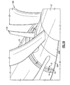
- FIG 1A schematically illustrates a pusher type counter-rotating propulsion system 10.
- An exhaust gas flow E of a gas turbine engine 12 is communicated through an annular exhaust nozzle 14 ( Figure 1B ) upstream of a first row of propeller blades 16A which rotate about an axis X.
- a second row of row of propeller blades 16B may be located downstream of the first row of propeller blades 16A in a counter-rotating propeller (CRP) propfan pusher configuration about the axis X.
- CRP counter-rotating propeller
- the annular exhaust nozzle 14 in one non-limiting embodiment is defined radially outboard of an annular cooling flow nozzle 18.
- a cooling flow C and/or other airflow that is different from the exhaust gas flow E is communicated through the annular cooling flow nozzle 18.
- the cooling flow C may be sourced from, for example only, a compressor section of the gas turbine engine 12, an inlet or other source.
- the annular exhaust nozzle 14 and annular cooling flow nozzle 18 form an annular nozzle section 15 generally upstream of the first row of propeller blades 16A.
- the annular exhaust nozzle 14 and annular cooling flow nozzle 18 may be radially defined between a radially outboard engine nacelle 23 and a radially inboard first spinner section 20A which mounts the first row of propeller blades 16A ( Figure 1B ).
- a second spinner section 20B which mounts the second row of propeller blades 16B is downstream of the first spinner section 20A.
- the second spinner section 20B counter rotates relative the first spinner section 20A while a tail cone 21 is located downstream of the second spinner section 20B.
- the tail cone 21 is aerodynamically shaped and in one embodiment remains rotationally stationary to facilitate flow.
- the nozzles 14, 18 have a relatively low profile and are aerodynamically shaped to minimize noise, drag and weight.
- the exhaust gas flow and the cooling flow are substantially uniform and directed through the first and second row of propeller blades 16A, 16B to avoid significant noise addition.
- the nozzles 14, 18 direct the exhaust stream E and the cooling flow C aftward such that at least a portion of the propulsive energy within the streams are exploited.
- the cooling flow C is directed, essentially under the annular exhaust gas flow E to enter each blade 22 at a root section 24 thereof. It should be understood that although only a single propeller blade 22 will be described, the description is similarly applicable to each of the propeller blades 22 in the first row of propeller blades 16A and/or the second row of propeller blades 16B.
- the cooling flow C operates to lower the temperature of the root section 24 which is proximate the exhaust gas flow E as well as film cool and insulate the spinner sections 20A, 20B and tail cone 21 at least partially from the exhaust gas flow E.
- the root section 24 may additionally be mechanically insulated or otherwise hardened to further resist the exhaust gas flow E.
- the root section 24 includes an intake 26 which communicates with a distribution channel 28.
- the distribution channel 28 may be defined at least in part by hollow airfoil sections and/or passages in the blade 22.
- the cooling flow C is communicated through the distribution channel 28 to an exit 30. Once the cooling flow enters the blade 22, the cooling flow C is self-pumped, by the rotational force of blade 22, through the distribution channel 28 which results in thrust recovery when ejected from the exit 30.
- the exit 30 may be located adjacent a trailing edge section 32 and/or a blade tip section 34. The exit 30 alternatively or additionally be distributed along the blade trailing edge section 32 to minimize an airfoil wake deficit with a corresponding potential noise reduction.
- the cooling flow may additionally be directed through a forward distribution channel section 28A adjacent a leading edge section 36 where hot gas impingement exists so as to reduce noise generation while the annular exhaust flow path is generally maintained.
Landscapes
- Engineering & Computer Science (AREA)
- Mechanical Engineering (AREA)
- General Engineering & Computer Science (AREA)
- Chemical & Material Sciences (AREA)
- Combustion & Propulsion (AREA)
- Turbine Rotor Nozzle Sealing (AREA)
- Exhaust Silencers (AREA)
Applications Claiming Priority (1)
| Application Number | Priority Date | Filing Date | Title |
|---|---|---|---|
| US12/030,400 US8210798B2 (en) | 2008-02-13 | 2008-02-13 | Cooled pusher propeller system |
Publications (2)
| Publication Number | Publication Date |
|---|---|
| EP2090765A2 true EP2090765A2 (fr) | 2009-08-19 |
| EP2090765A3 EP2090765A3 (fr) | 2013-02-13 |
Family
ID=40469819
Family Applications (1)
| Application Number | Title | Priority Date | Filing Date |
|---|---|---|---|
| EP09250260A Withdrawn EP2090765A3 (fr) | 2008-02-13 | 2009-01-30 | Système de propulsion à pousseur refroidi et procédé d'orientation du flux de sortie d'un système propulsif |
Country Status (2)
| Country | Link |
|---|---|
| US (2) | US8210798B2 (fr) |
| EP (1) | EP2090765A3 (fr) |
Cited By (5)
| Publication number | Priority date | Publication date | Assignee | Title |
|---|---|---|---|---|
| EP2233394A2 (fr) | 2009-02-12 | 2010-09-29 | Hamilton Sundstrand Corporation | Hélice dotée de pales protégées thermiquement |
| GB2474448A (en) * | 2009-10-14 | 2011-04-20 | Rolls Royce Plc | A cooling system for an open rotor gas turbine engine |
| WO2014163708A3 (fr) * | 2013-03-08 | 2014-12-11 | Rolls-Royce Corporation | Suppression de bruit de rotor |
| WO2020025886A1 (fr) | 2018-08-03 | 2020-02-06 | Safran Aircraft Engines | Turbomachine a helices coaxiales |
| RU2784237C2 (ru) * | 2018-08-03 | 2022-11-23 | Сафран Эркрафт Энджинз | Газотурбинный двигатель с коаксиальными винтами |
Families Citing this family (23)
| Publication number | Priority date | Publication date | Assignee | Title |
|---|---|---|---|---|
| US8210798B2 (en) * | 2008-02-13 | 2012-07-03 | United Technologies Corporation | Cooled pusher propeller system |
| US8540481B2 (en) * | 2010-04-13 | 2013-09-24 | Rolls-Royce Corporation | Rotor blade assembly |
| GB201007063D0 (en) * | 2010-04-28 | 2010-06-09 | Rolls Royce Plc | A gas turbine engine |
| US8845270B2 (en) * | 2010-09-10 | 2014-09-30 | Rolls-Royce Corporation | Rotor assembly |
| GB201101609D0 (en) * | 2011-01-31 | 2011-03-16 | Rolls Royce Plc | Attenuation of open rotor noise |
| FR2992346B1 (fr) * | 2012-06-22 | 2016-12-23 | Snecma | Helice non carenee de turbomachine d'aeronef presentant des pieds de pales refroidis par des conduits d'air de refroidissement traversant les pales |
| GB201212072D0 (en) * | 2012-07-06 | 2012-08-22 | Rolls Royce Plc | Fluid intake and system for rotary machines |
| EP3166846B1 (fr) | 2014-07-08 | 2019-03-20 | Sikorsky Aircraft Corporation | Rotation de rotor désolidarisé |
| US10953982B2 (en) | 2014-09-30 | 2021-03-23 | Sikorsky Aircraft Corporation | Rotorcraft including auxiliary propulsor positioned to ingest boundary layer flow |
| US10711631B2 (en) | 2014-12-24 | 2020-07-14 | Raytheon Technologies Corporation | Turbine engine with guide vanes forward of its fan blades |
| US10421553B2 (en) | 2015-01-20 | 2019-09-24 | United Technologies Corporation | Pusher fan engine with in wing configuration |
| US10876407B2 (en) * | 2017-02-16 | 2020-12-29 | General Electric Company | Thermal structure for outer diameter mounted turbine blades |
| US11401824B2 (en) | 2019-10-15 | 2022-08-02 | General Electric Company | Gas turbine engine outlet guide vane assembly |
| US11834196B2 (en) | 2019-10-15 | 2023-12-05 | General Electric Company | System and method for control for unducted engine |
| US11286795B2 (en) * | 2019-10-15 | 2022-03-29 | General Electric Company | Mount for an airfoil |
| US11506067B2 (en) | 2019-10-15 | 2022-11-22 | General Electric Company | Gas turbine engine with clutch assembly |
| US12103702B2 (en) | 2019-10-15 | 2024-10-01 | General Electric Company | Removeable fuselage shield for an aircraft |
| US11772784B2 (en) | 2020-07-20 | 2023-10-03 | Lockheed Martin Corporation | Multi-purpose prop-rotor spinner arrangement |
| US11719248B2 (en) | 2020-10-14 | 2023-08-08 | Pratt & Whitney Canada Corp. | Aircraft propulsion system with propeller and cooling fan |
| US12410758B2 (en) | 2022-01-10 | 2025-09-09 | General Electric Company | Three-stream gas turbine engine control |
| US12275532B2 (en) | 2022-08-15 | 2025-04-15 | General Electric Company | Gas turbine engine noise reduction |
| US12480449B2 (en) | 2022-08-22 | 2025-11-25 | General Electric Company | Propulsion system including an electric machine for starting a gas turbine engine |
| US12352181B2 (en) | 2023-01-30 | 2025-07-08 | General Electric Company | Turbine airfoils |
Citations (4)
| Publication number | Priority date | Publication date | Assignee | Title |
|---|---|---|---|---|
| US2586054A (en) | 1948-08-21 | 1952-02-19 | Northrop Aircraft Inc | Pusher turboprop exhaust system |
| US2627927A (en) | 1947-05-29 | 1953-02-10 | Curtiss Wright Corp | Propeller temperature control means |
| US4892269A (en) | 1988-04-28 | 1990-01-09 | Allied-Signal Inc. | Spinner ducted exhaust for pusher turboprop engines |
| US5186609A (en) | 1990-12-20 | 1993-02-16 | Honda Giken Kogyo Kabushiki Kaisha | Contrarotating propeller type propulsion system |
Family Cites Families (34)
| Publication number | Priority date | Publication date | Assignee | Title |
|---|---|---|---|---|
| DE763600C (de) | 1939-03-25 | 1951-08-09 | Focke Wulf Flugzeugbau G M B H | Mit einer Luftschraube umlaufende, aus einer inneren Nabenhaube und einer aeusseren Ringhaube bestehende Doppelhaube |
| FR860037A (fr) | 1939-09-02 | 1941-01-04 | Fouga & Cie Ets | Cache-moyeu d'hélice-ventilateur |
| FR999942A (fr) | 1946-02-05 | 1952-02-06 | Sncaso | Dispositif de propulsion dans un milieu fluide |
| US3963368A (en) * | 1967-12-19 | 1976-06-15 | General Motors Corporation | Turbine cooling |
| US3811791A (en) * | 1971-08-12 | 1974-05-21 | R Cotton | Thrust augmenting device for jet aircraft |
| US4171183A (en) * | 1976-09-24 | 1979-10-16 | United Technologies Corporation | Multi-bladed, high speed prop-fan |
| GB2117054B (en) * | 1982-02-17 | 1985-01-30 | Rolls Royce | Aircraft propulsion engine having a rear mounted propfan |
| US4569199A (en) * | 1982-09-29 | 1986-02-11 | The Boeing Company | Turboprop engine and method of operating the same |
| GB2173863B (en) * | 1985-04-17 | 1989-07-19 | Rolls Royce Plc | A propeller module for an aero gas turbine engine |
| US4817382A (en) * | 1985-12-31 | 1989-04-04 | The Boeing Company | Turboprop propulsion apparatus |
| US4789304A (en) * | 1987-09-03 | 1988-12-06 | United Technologies Corporation | Insulated propeller blade |
| US4864820A (en) * | 1987-10-22 | 1989-09-12 | United Technologies Corporation | Exhaust nozzle |
| US4930725A (en) * | 1988-12-16 | 1990-06-05 | Allied-Signal Inc. | Pusher propeller installation for turboprop engines |
| US5720431A (en) * | 1988-08-24 | 1998-02-24 | United Technologies Corporation | Cooled blades for a gas turbine engine |
| DE3828834C1 (fr) * | 1988-08-25 | 1989-11-02 | Mtu Muenchen Gmbh | |
| US5931637A (en) * | 1996-01-22 | 1999-08-03 | Something Else Limited Liability Company | Propeller with variable rate of pitch change |
| US6041589A (en) * | 1998-01-09 | 2000-03-28 | General Electric Company | Asymmetric turboprop booster |
| US6203269B1 (en) * | 1999-02-25 | 2001-03-20 | United Technologies Corporation | Centrifugal air flow control |
| US6514044B2 (en) * | 2000-12-21 | 2003-02-04 | Hamilton Sundstrand Corporation | Offset crowned roller assembly for variable pitch propellers |
| US6422816B1 (en) * | 2001-05-21 | 2002-07-23 | Hamilton Sundstrand Corporation | Variable pitch propeller control system |
| US6511292B2 (en) * | 2001-06-27 | 2003-01-28 | Hamilton Sundstrand Corporation | Backup governing system for a variable pitch propeller |
| US6651929B2 (en) * | 2001-10-29 | 2003-11-25 | Pratt & Whitney Canada Corp. | Passive cooling system for auxiliary power unit installation |
| US6769874B2 (en) * | 2002-03-15 | 2004-08-03 | Hamilton Sundstrand | Permanent magnet alternator for a gas turbine engine |
| US6753513B2 (en) * | 2002-03-19 | 2004-06-22 | Hamilton Sundstrand | Propeller de-icing system |
| US6811376B2 (en) * | 2002-03-19 | 2004-11-02 | Hamilton Sundstrand | Actuation system for a controllable pitch propeller |
| US6851929B2 (en) * | 2002-03-19 | 2005-02-08 | Hamilton Sundstrand | System for powering and controlling a device associated with a rotating component on aircraft |
| US6981844B2 (en) * | 2003-10-08 | 2006-01-03 | Hamilton Sundstrand | Cyclic actuation system for a controllable pitch propeller and a method of providing aircraft control therewith |
| US7198468B2 (en) * | 2004-07-15 | 2007-04-03 | Pratt & Whitney Canada Corp. | Internally cooled turbine blade |
| GB2417295B (en) * | 2004-08-21 | 2006-10-25 | Rolls Royce Plc | A component having a cooling arrangement |
| US20060137355A1 (en) * | 2004-12-27 | 2006-06-29 | Pratt & Whitney Canada Corp. | Fan driven emergency generator |
| US7159817B2 (en) * | 2005-01-13 | 2007-01-09 | Vandermey Timothy | Vertical take-off and landing (VTOL) aircraft with distributed thrust and control |
| US7296969B2 (en) * | 2005-10-12 | 2007-11-20 | Hamilton Sundstrand Corporation | Propeller pitch change system |
| US8016561B2 (en) * | 2006-07-11 | 2011-09-13 | General Electric Company | Gas turbine engine fan assembly and method for assembling to same |
| US8210798B2 (en) * | 2008-02-13 | 2012-07-03 | United Technologies Corporation | Cooled pusher propeller system |
-
2008
- 2008-02-13 US US12/030,400 patent/US8210798B2/en active Active
-
2009
- 2009-01-30 EP EP09250260A patent/EP2090765A3/fr not_active Withdrawn
-
2012
- 2012-05-31 US US13/484,641 patent/US8764381B2/en active Active
Patent Citations (4)
| Publication number | Priority date | Publication date | Assignee | Title |
|---|---|---|---|---|
| US2627927A (en) | 1947-05-29 | 1953-02-10 | Curtiss Wright Corp | Propeller temperature control means |
| US2586054A (en) | 1948-08-21 | 1952-02-19 | Northrop Aircraft Inc | Pusher turboprop exhaust system |
| US4892269A (en) | 1988-04-28 | 1990-01-09 | Allied-Signal Inc. | Spinner ducted exhaust for pusher turboprop engines |
| US5186609A (en) | 1990-12-20 | 1993-02-16 | Honda Giken Kogyo Kabushiki Kaisha | Contrarotating propeller type propulsion system |
Cited By (10)
| Publication number | Priority date | Publication date | Assignee | Title |
|---|---|---|---|---|
| EP2233394A2 (fr) | 2009-02-12 | 2010-09-29 | Hamilton Sundstrand Corporation | Hélice dotée de pales protégées thermiquement |
| EP2233394A3 (fr) * | 2009-02-12 | 2013-04-03 | Hamilton Sundstrand Corporation | Hélice dotée de pales protégées thermiquement |
| GB2474448A (en) * | 2009-10-14 | 2011-04-20 | Rolls Royce Plc | A cooling system for an open rotor gas turbine engine |
| US8568086B2 (en) | 2009-10-14 | 2013-10-29 | Rolls-Royce Plc | Cooling system |
| WO2014163708A3 (fr) * | 2013-03-08 | 2014-12-11 | Rolls-Royce Corporation | Suppression de bruit de rotor |
| US9650962B2 (en) | 2013-03-08 | 2017-05-16 | Rolls-Royce Corporation | Rotor noise suppression |
| WO2020025886A1 (fr) | 2018-08-03 | 2020-02-06 | Safran Aircraft Engines | Turbomachine a helices coaxiales |
| FR3084693A1 (fr) * | 2018-08-03 | 2020-02-07 | Safran Aircraft Engines | Turbomachine a helices non carenees |
| RU2784237C2 (ru) * | 2018-08-03 | 2022-11-23 | Сафран Эркрафт Энджинз | Газотурбинный двигатель с коаксиальными винтами |
| US11542891B2 (en) | 2018-08-03 | 2023-01-03 | Safran Aircraft Engines | Turbomachine with coaxial propellers |
Also Published As
| Publication number | Publication date |
|---|---|
| EP2090765A3 (fr) | 2013-02-13 |
| US20120237359A1 (en) | 2012-09-20 |
| US8210798B2 (en) | 2012-07-03 |
| US8764381B2 (en) | 2014-07-01 |
| US20090202357A1 (en) | 2009-08-13 |
Similar Documents
| Publication | Publication Date | Title |
|---|---|---|
| US8210798B2 (en) | Cooled pusher propeller system | |
| US8061657B2 (en) | Method and apparatus for aircraft anti-icing | |
| CN115675836B (zh) | 无导管推力产生系统 | |
| US8256709B2 (en) | Aircraft with tail propeller-engine layout | |
| EP1918199B1 (fr) | Architecture de cellule d'avion | |
| CA2722099C (fr) | Reduction du degivrage pour structures de bord d'attaque | |
| US10167085B2 (en) | Nozzle and vane system for nacelle anti-icing | |
| EP2685065B1 (fr) | Turbopropulseur | |
| EP2903894B1 (fr) | Prise d'air à entrée bifurquée pour moteur à turbine à gaz | |
| US7850116B2 (en) | Ducted open rotor apparatus and method | |
| CA2618661A1 (fr) | Systeme de suppression de la signature infrarouge | |
| US20160076487A1 (en) | System and Method for Improved Thrust Reverser With Increased Reverse Thrust and Reduced Noise | |
| GB2211247A (en) | Turboprop exhaust nozzle | |
| WO1989010300A1 (fr) | Echappement a capot de moyeu d'helice canalise pour turbopropulseur | |
| US10974813B2 (en) | Engine nacelle for an aircraft | |
| CN213331289U (zh) | 进气整流罩、燃气涡轮发动机以及飞机 | |
| RU2361779C1 (ru) | Силовая установка с отбором пограничного слоя фюзеляжа | |
| US12280883B2 (en) | Open rotor pylon fairing | |
| US12448139B2 (en) | Open rotor pylon fairing | |
| US20250304266A1 (en) | Cooling of gas flowing over aircraft structure | |
| RU196303U1 (ru) | Воздушный движитель черногорова | |
| US20240239504A1 (en) | Open rotor pylon fairing | |
| EP4571074A1 (fr) | Nacelle pour turbopropulseurs | |
| US20260125159A1 (en) | Aircraft and Method for Operating | |
| CN118358764A (zh) | 开式转子吊架整流罩 |
Legal Events
| Date | Code | Title | Description |
|---|---|---|---|
| PUAI | Public reference made under article 153(3) epc to a published international application that has entered the european phase |
Free format text: ORIGINAL CODE: 0009012 |
|
| AK | Designated contracting states |
Kind code of ref document: A2 Designated state(s): AT BE BG CH CY CZ DE DK EE ES FI FR GB GR HR HU IE IS IT LI LT LU LV MC MK MT NL NO PL PT RO SE SI SK TR |
|
| AX | Request for extension of the european patent |
Extension state: AL BA RS |
|
| PUAL | Search report despatched |
Free format text: ORIGINAL CODE: 0009013 |
|
| AK | Designated contracting states |
Kind code of ref document: A3 Designated state(s): AT BE BG CH CY CZ DE DK EE ES FI FR GB GR HR HU IE IS IT LI LT LU LV MC MK MT NL NO PL PT RO SE SI SK TR |
|
| AX | Request for extension of the european patent |
Extension state: AL BA RS |
|
| RIC1 | Information provided on ipc code assigned before grant |
Ipc: F02K 3/072 20060101ALI20130108BHEP Ipc: F01D 1/26 20060101ALI20130108BHEP Ipc: F01D 5/18 20060101ALI20130108BHEP Ipc: F02C 7/12 20060101AFI20130108BHEP Ipc: F02C 6/20 20060101ALI20130108BHEP |
|
| 17P | Request for examination filed |
Effective date: 20130731 |
|
| RBV | Designated contracting states (corrected) |
Designated state(s): AT BE BG CH CY CZ DE DK EE ES FI FR GB GR HR HU IE IS IT LI LT LU LV MC MK MT NL NO PL PT RO SE SI SK TR |
|
| 17Q | First examination report despatched |
Effective date: 20130822 |
|
| AKX | Designation fees paid |
Designated state(s): DE GB |
|
| STAA | Information on the status of an ep patent application or granted ep patent |
Free format text: STATUS: THE APPLICATION IS DEEMED TO BE WITHDRAWN |
|
| 18D | Application deemed to be withdrawn |
Effective date: 20140103 |