EP2090797A2 - Procédé de commande pour un embrayage de véhicule - Google Patents
Procédé de commande pour un embrayage de véhicule Download PDFInfo
- Publication number
- EP2090797A2 EP2090797A2 EP09150927A EP09150927A EP2090797A2 EP 2090797 A2 EP2090797 A2 EP 2090797A2 EP 09150927 A EP09150927 A EP 09150927A EP 09150927 A EP09150927 A EP 09150927A EP 2090797 A2 EP2090797 A2 EP 2090797A2
- Authority
- EP
- European Patent Office
- Prior art keywords
- clutch
- signal
- pressure
- actual
- control unit
- Prior art date
- Legal status (The legal status is an assumption and is not a legal conclusion. Google has not performed a legal analysis and makes no representation as to the accuracy of the status listed.)
- Granted
Links
- 238000000034 method Methods 0.000 title claims abstract description 30
- 230000005540 biological transmission Effects 0.000 claims abstract description 60
- 230000008878 coupling Effects 0.000 claims description 11
- 238000010168 coupling process Methods 0.000 claims description 11
- 238000005859 coupling reaction Methods 0.000 claims description 11
- 230000001105 regulatory effect Effects 0.000 claims description 10
- 230000000694 effects Effects 0.000 claims description 4
- 238000005259 measurement Methods 0.000 abstract description 2
- 238000010586 diagram Methods 0.000 description 7
- 239000012530 fluid Substances 0.000 description 5
- 238000013016 damping Methods 0.000 description 4
- 238000002485 combustion reaction Methods 0.000 description 2
- 230000009977 dual effect Effects 0.000 description 2
- QABBQIGDZQUNKN-UHFFFAOYSA-N 5-phenyldithiol-3-imine Chemical compound S1SC(=N)C=C1C1=CC=CC=C1 QABBQIGDZQUNKN-UHFFFAOYSA-N 0.000 description 1
- 101100002669 Arabidopsis thaliana ADT1 gene Proteins 0.000 description 1
- 101100002673 Arabidopsis thaliana ADT3 gene Proteins 0.000 description 1
- 101100463170 Schizosaccharomyces pombe (strain 972 / ATCC 24843) pdt1 gene Proteins 0.000 description 1
- 150000001875 compounds Chemical class 0.000 description 1
- 230000001276 controlling effect Effects 0.000 description 1
- 238000005429 filling process Methods 0.000 description 1
- 238000002955 isolation Methods 0.000 description 1
Images
Classifications
-
- F—MECHANICAL ENGINEERING; LIGHTING; HEATING; WEAPONS; BLASTING
- F16—ENGINEERING ELEMENTS AND UNITS; GENERAL MEASURES FOR PRODUCING AND MAINTAINING EFFECTIVE FUNCTIONING OF MACHINES OR INSTALLATIONS; THERMAL INSULATION IN GENERAL
- F16D—COUPLINGS FOR TRANSMITTING ROTATION; CLUTCHES; BRAKES
- F16D48/00—External control of clutches
- F16D48/06—Control by electric or electronic means, e.g. of fluid pressure
- F16D48/066—Control of fluid pressure, e.g. using an accumulator
-
- F—MECHANICAL ENGINEERING; LIGHTING; HEATING; WEAPONS; BLASTING
- F16—ENGINEERING ELEMENTS AND UNITS; GENERAL MEASURES FOR PRODUCING AND MAINTAINING EFFECTIVE FUNCTIONING OF MACHINES OR INSTALLATIONS; THERMAL INSULATION IN GENERAL
- F16D—COUPLINGS FOR TRANSMITTING ROTATION; CLUTCHES; BRAKES
- F16D2500/00—External control of clutches by electric or electronic means
- F16D2500/10—System to be controlled
- F16D2500/102—Actuator
- F16D2500/1026—Hydraulic
-
- F—MECHANICAL ENGINEERING; LIGHTING; HEATING; WEAPONS; BLASTING
- F16—ENGINEERING ELEMENTS AND UNITS; GENERAL MEASURES FOR PRODUCING AND MAINTAINING EFFECTIVE FUNCTIONING OF MACHINES OR INSTALLATIONS; THERMAL INSULATION IN GENERAL
- F16D—COUPLINGS FOR TRANSMITTING ROTATION; CLUTCHES; BRAKES
- F16D2500/00—External control of clutches by electric or electronic means
- F16D2500/10—System to be controlled
- F16D2500/108—Gear
- F16D2500/1086—Concentric shafts
-
- F—MECHANICAL ENGINEERING; LIGHTING; HEATING; WEAPONS; BLASTING
- F16—ENGINEERING ELEMENTS AND UNITS; GENERAL MEASURES FOR PRODUCING AND MAINTAINING EFFECTIVE FUNCTIONING OF MACHINES OR INSTALLATIONS; THERMAL INSULATION IN GENERAL
- F16D—COUPLINGS FOR TRANSMITTING ROTATION; CLUTCHES; BRAKES
- F16D2500/00—External control of clutches by electric or electronic means
- F16D2500/30—Signal inputs
- F16D2500/302—Signal inputs from the actuator
- F16D2500/3024—Pressure
-
- F—MECHANICAL ENGINEERING; LIGHTING; HEATING; WEAPONS; BLASTING
- F16—ENGINEERING ELEMENTS AND UNITS; GENERAL MEASURES FOR PRODUCING AND MAINTAINING EFFECTIVE FUNCTIONING OF MACHINES OR INSTALLATIONS; THERMAL INSULATION IN GENERAL
- F16D—COUPLINGS FOR TRANSMITTING ROTATION; CLUTCHES; BRAKES
- F16D2500/00—External control of clutches by electric or electronic means
- F16D2500/30—Signal inputs
- F16D2500/304—Signal inputs from the clutch
- F16D2500/30404—Clutch temperature
-
- F—MECHANICAL ENGINEERING; LIGHTING; HEATING; WEAPONS; BLASTING
- F16—ENGINEERING ELEMENTS AND UNITS; GENERAL MEASURES FOR PRODUCING AND MAINTAINING EFFECTIVE FUNCTIONING OF MACHINES OR INSTALLATIONS; THERMAL INSULATION IN GENERAL
- F16D—COUPLINGS FOR TRANSMITTING ROTATION; CLUTCHES; BRAKES
- F16D2500/00—External control of clutches by electric or electronic means
- F16D2500/30—Signal inputs
- F16D2500/316—Other signal inputs not covered by the groups above
- F16D2500/3168—Temperature detection of any component of the control system
-
- F—MECHANICAL ENGINEERING; LIGHTING; HEATING; WEAPONS; BLASTING
- F16—ENGINEERING ELEMENTS AND UNITS; GENERAL MEASURES FOR PRODUCING AND MAINTAINING EFFECTIVE FUNCTIONING OF MACHINES OR INSTALLATIONS; THERMAL INSULATION IN GENERAL
- F16D—COUPLINGS FOR TRANSMITTING ROTATION; CLUTCHES; BRAKES
- F16D2500/00—External control of clutches by electric or electronic means
- F16D2500/50—Problem to be solved by the control system
- F16D2500/506—Relating the transmission
- F16D2500/5063—Shaft dither, i.e. applying a pulsating torque to a (transmission) shaft to create a buzz or dither, e.g. to prevent tooth butting or gear locking
-
- F—MECHANICAL ENGINEERING; LIGHTING; HEATING; WEAPONS; BLASTING
- F16—ENGINEERING ELEMENTS AND UNITS; GENERAL MEASURES FOR PRODUCING AND MAINTAINING EFFECTIVE FUNCTIONING OF MACHINES OR INSTALLATIONS; THERMAL INSULATION IN GENERAL
- F16D—COUPLINGS FOR TRANSMITTING ROTATION; CLUTCHES; BRAKES
- F16D2500/00—External control of clutches by electric or electronic means
- F16D2500/70—Details about the implementation of the control system
- F16D2500/704—Output parameters from the control unit; Target parameters to be controlled
- F16D2500/70402—Actuator parameters
- F16D2500/70406—Pressure
-
- F—MECHANICAL ENGINEERING; LIGHTING; HEATING; WEAPONS; BLASTING
- F16—ENGINEERING ELEMENTS AND UNITS; GENERAL MEASURES FOR PRODUCING AND MAINTAINING EFFECTIVE FUNCTIONING OF MACHINES OR INSTALLATIONS; THERMAL INSULATION IN GENERAL
- F16D—COUPLINGS FOR TRANSMITTING ROTATION; CLUTCHES; BRAKES
- F16D2500/00—External control of clutches by electric or electronic means
- F16D2500/70—Details about the implementation of the control system
- F16D2500/706—Strategy of control
- F16D2500/70668—Signal filtering
Definitions
- the present invention relates to a method for driving a clutch of a vehicle drive train, in particular a vehicle drive train with a dual-clutch transmission.
- Dual clutch transmissions are well known. They include a dual-clutch arrangement with two parallel friction clutches and a stepped transmission with two parallel partial transmissions. A branch with a first friction clutch and a first partial transmission, the odd gear ratios are assigned. The other branch with the second friction clutch and the second partial transmission, the even gears are assigned. On the input side, the friction clutches are connected to a drive motor, for example an internal combustion engine, a hybrid drive unit or the like.
- the partial transmissions are usually realized as a spur gear.
- the compound of the friction clutch assembly with the partial transmissions via a shaft assembly having an inner shaft and a concentrically arranged thereto hollow shaft.
- gear changes can be performed without interruption of traction.
- the operation of the friction clutches is automated.
- the actuators used for this purpose must be precisely controlled in particular in the transfer of the drive torque from one friction clutch to the other friction clutch to ensure a smooth gear change.
- a method for driving a clutch of a vehicle drive train wherein a controller of an electronic control unit generates a desired electric signal corresponding to a target pressure to be applied to the clutch, wherein the control unit of a Sensor receives an electrical actual signal, which is to correspond to an actual pressure, with which the clutch is acted upon, wherein the sensor measures the pressure at a measuring location, which is connected via a transmission path to a loading location, to which the clutch is subjected to a clutch pressure, and wherein the actual signal passes through a transmission element with a delay characteristic before it is fed to the controller.
- the inventive measure the first supply signal to a transmission element with a delay characteristic before it is fed to the controller, this problem can be eliminated. In this way, in particular, a larger control difference between the desired value and the respective actual value can be achieved.
- the controller can work better hereby.
- delay property is to be understood broadly in the present case. A delay should accordingly be achieved with a pure delay element become. To the same extent, however, this delay property can also be reduced by a transmission element which, for example, simulates a PT1 function (PT1 element).
- the delay characteristic of the transmission element is a function of the temperature.
- the extent of the delay at higher temperatures is preferably set smaller, since the system is then more in a steady state and can work more precisely anyway.
- the temperature may be, for example, the temperature of a fluid, such as an oil, with which the clutch is driven. Alternatively, the temperature may also be the temperature of an electric actuator motor or an associated power stage. However, the temperature is preferably a temperature which is related to the temperature of the coupling itself, preferably in a proportional relationship.
- the delay characteristic of the transmission element is a function of the desired pressure.
- the degree of delay of the transmission element is set correspondingly smaller, since in this case the controller receives a relatively high control difference anyway.
- the coupling is fluidically, in particular hydraulically actuated and when the actual signal is a pressure signal of a pressure sensor.
- the coupling is actuated electromechanically or electromagnetically, wherein the actual signal is a current signal of an electric current sensor.
- a hydraulic actuator In a hydraulic actuator, the influence of a hydraulic transmission path can be particularly large, so that the invention has particular advantages. Even with an electric actuator, however, a transmission path between the measuring location and the application site can be present, which can be compensated by the method according to the invention.
- the above object is achieved by a method for driving a clutch of a vehicle drive train, wherein an electronic control unit generates a target electric signal corresponding to a target pressure to be applied to the clutch, the control unit being controlled by a sensor receives an electrical actual signal, which is to correspond to an actual pressure, with which the clutch is acted upon, and wherein the desired signal is modulated with a higher-frequency signal (dither) to minimize hysteresis effects.
- the method according to the invention is applicable in particular during the filling phase.
- the method according to the invention can also be used in other phases of the coupling control.
- the desired signal is modulated with the higher-frequency signal at least during a section of the filling phase.
- the modulation of the desired signal is preferably terminated a certain time before the predicted reaching of the engagement point at which the torque transmission exceeds a certain level.
- the setpoint signal is generated by the control unit during a filling phase of the clutch, starting from an open basic state of the clutch in the direction of an engagement point of the clutch first in the form of an unregulated, ie controlled signal and then in the form of a controlled signal depending on an actual value ,
- the filling phase first by an unregulated, i.
- an unregulated i.
- the unregulated signal is an excessive signal.
- An excessive signal is understood to be a signal which is controlled such that it lies at least in sections above the desired target value for reaching the point of engagement of the clutch.
- the overdriven controlled signal may be given a PDTI characteristic, that is, initially a high peak and then a falling curve.
- the falling curve can be similar to a PT1 member or similar to a PI function.
- the actual control of the signal in the subsequent phase can be done for example via a PI controller.
- the clutch may be a dry clutch, but is preferably a wet-running clutch such as a wet-running multi-plate clutch.
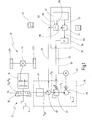
- Fig. 1 is a motor vehicle such as a passenger car generally designated 10.
- the motor vehicle 10 has a drive train 12 with a drive motor 14.
- the drive motor 14 may be, for example, an internal combustion engine or a hybrid drive unit.
- the drive train 12 also has a friction clutch 16, which is shown here as a single clutch in the form of a starting clutch.
- the drive train 12 has a stepped transmission 18, for example in the form of a spur or countershaft transmission.
- the output of the stepped transmission 18 is connected to a transaxle 20, which distributes the driving force to driven wheels 22L, 22R of the motor vehicle 10.
- a hydraulic actuation by means of a hydraulic actuator 24 This usually has a piston, the clutch via a hydraulic fluid (for example ATF- ⁇ 1) presses, with a force F K , which is proportional to a clutch pressure P K.
- the hydraulic actuator 24 is controlled via a hydraulic circuit 26. Furthermore, the motor vehicle 10 has an electrical control unit 30, by means of which the hydraulic circuit 26 can be controlled.
- the electrical control unit 30 has a control device 32, for example in the form of a microcontroller and a controller 34.
- the controller 34 may be part of the control device 32 or may be provided as a separate component within the control unit 30.
- the control unit 30 includes a digital / analog converter 36, which converts digital control signals of the controller 34 into analog signals which are supplied to the hydraulic circuit 26.
- the hydraulic circuit 26 has a fluid pump 40, which generates a line pressure P L in conjunction with a pressure regulating valve.
- the fluid is sucked in from an unspecified tank.
- the pump 40 may then be driven, for example, by means of an electric motor 42 (or as an accessory via the crankshaft of the drive motor 14).
- the fluid provided by the pump 40 may be used to cool the friction clutch 16. For reasons of clarity, these lines are not shown.
- the hydraulic circuit 26 also has a pressure regulating valve (in particular pressure reducing valve) 44, which generates a regulated pressure P R for the control of the hydraulic actuator 24 from the line pressure P L.
- the regulated pressure P R is provided to the actuator 24 via a hydraulic transmission path 46 (for example, a rotary union, hydraulic lines, etc.).
- the hydraulic circuit 26 includes a pressure sensor 48 provided in association with the pressure regulating valve 44.
- the hydraulic transmission path 46 is arranged between the pressure sensor 48 and the actuator 24.
- the control unit 30 further comprises a transmission member 50, with which a signal from the pressure sensor 48 is subjected to a delay or damping before this signal is supplied to the controller 34.
- the transmission member 50 may be part of the control device 32, so be simulated by software.
- the control device 32 generates a signal for a desired pressure 58 on the basis of superordinate control parameters. This signal is fed to the controller 34.
- the controller 34 generates a digital command signal 60, which is converted in the digital / analog converter 36 into an analog command signal 62.
- the analog target signal 62 is supplied to the pressure control valve 44 and controls the regulated pressure P R.
- the pressure sensor 48 generates an actual signal 64 (P actual ) which is input to the transmission member 50.
- P actual an actual signal 64
- the actual signal 64 experiences a delay or damping.
- the corrected in this way actual signal 66 is supplied to the controller 34.
- control unit 30 may also be configured to provide a motor control signal 67 for the electric motor 42. Also is in Fig. 1 that the controller 32 sets the delay characteristic of the transmission member 50 in accordance with the temperature (temperature setting signal 68). Alternatively or cumulatively, the deceleration property of the transmission member 50 may also be adjusted depending on the respective generated desired pressure 58 (shown by a target pressure adjustment signal 69).
- the transmission member 50 can be generally used in the context of driving the friction clutch 16. Preferably, however, it is used when the clutch 16 is filled, that is, is shifted from an open state to a state in which the point of engagement of the clutch is reached. In other cases, the transmission member 50 may also be bypassed if necessary.
- an exact control difference between the target pressure and the actual pressure in the clutch piston chamber based on the measured signal 64 can be calculated .. This allows the controller to work better. At higher temperatures, the deceleration property tends to be reduced. Correspondingly, at higher target pressures (and / or at higher actual pressures after the delay element 66), the deceleration property can also be reduced.
- an electric actuator can be used instead of a hydraulic actuator 24, instead of a hydraulic circuit 26, an electric or electronic circuit would be used, by means of which the corresponding drive signals for the electric actuator are generated.
- an electrical transmission path (corresponding to the transmission path 46) can lie between the value of a then usually occurring electric current measurement (corresponding to the pressure sensor 48) and the location at which the electric current is finally used due to the electric actuator 24.
- a transmission member 50 of the type described above can be used.
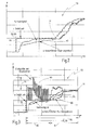
- a diagram 70 is shown, in which the filling operation is initiated by an increase of the desired pressure by means of a jump signal.
- the filling phase essentially ends at a point in time 71.
- the diagram 70 furthermore represents the actual signal 64 generated by the pressure sensor 48 (sensor signal). Further, in the graph 70, the corrected actual pressure 66 detected by the transmission member 50 is shown ("estimated clutch pressure").
- the transmission element 50 With its delay or damping characteristic, virtually forms the transmission path 46.
- the transmission member 50 thus fulfills the function of a pressure observer, by which the actual pressure in the actuator 24 is estimated. Because through the transmission path 46 of the present at a certain time in the region of the measuring location of the sensor 48 regulated pressure P R only a certain time later in the hydraulic actuator 24 as a clutch pressure P K "arrive". Through this dynamic influence of pressure by the transmission path 46 corresponds to the temperature measured by the sensor 48 the actual pressure P is not the actual pressure P K in the actuator 24 through the transmission member 50, this can be compensated for.
- the transmission member 50 having a deceleration characteristic which is a function of the temperature and / or the target pressure (arrows 68, 69), the dynamic behavior of the transmission link 46 can be more realistically estimated and thus compensated.
- a diagram 72 is shown, which in terms of the general sequence of the diagram 70 of Fig. 2 equivalent.
- a setpoint signal (manipulated variable with pressure generator) 60 is generated, which is modulated with a high-frequency signal having a modulation amplitude 74.
- a "dither" signal is superimposed on the desired signal.
- the filling phase of the coupling 16 is in Fig. 3 at 76 and lasts from raising the set pressure to reaching the point of engagement (at 71).
- the modulation of the desired signal 60 takes place in a modulation phase 78, which ends clearly before the engagement point 71.
- the modulation is exerted only in a "soft" region of the clutch, so that no influences on the drive train can be exercised (in particular no transmission of vibrations to the drive train).
- the filling phase 76 in the driving method of FIG Fig. 3 divided into a control phase 80 and a control phase 82.
- the setpoint signal 60 is not regulated by way of feedback but is predetermined in a controlled manner.
- the signal can have, for example, the characteristic of a PDT1 function.
- the setpoint signal 60 at the beginning of the control phase 80 receives a relatively high peak value, which is significantly above the setpoint pressure. Proceeding from this, the signal can then drop slightly again, for example in the manner of a PT1 element or a PI element.
- the control phase 80 likewise ends clearly before the point of engagement is reached, in particular even before the modulation phase 78 has ended.
- a control process is carried out in the controller 34 using the actual signal 64 (or the corrected actual signal 66).
- the modulation amplitude 74 can be significantly reduced.
- the system can be impressed by the controlled desired signal 60, a relatively rapid increase of the corresponding pressure values (the regulated pressure P R and consequently also the clutch pressure P K ).
- the subsequent control phase 82 an exact positioning or device of the clutch 16 for the engagement point 71 can take place.
Landscapes
- Physics & Mathematics (AREA)
- Fluid Mechanics (AREA)
- Engineering & Computer Science (AREA)
- General Engineering & Computer Science (AREA)
- Mechanical Engineering (AREA)
- Hydraulic Clutches, Magnetic Clutches, Fluid Clutches, And Fluid Joints (AREA)
Applications Claiming Priority (1)
| Application Number | Priority Date | Filing Date | Title |
|---|---|---|---|
| DE102008009094A DE102008009094B4 (de) | 2008-02-14 | 2008-02-14 | Verfahren zum Ansteuern einer Kupplung |
Publications (3)
| Publication Number | Publication Date |
|---|---|
| EP2090797A2 true EP2090797A2 (fr) | 2009-08-19 |
| EP2090797A3 EP2090797A3 (fr) | 2011-04-27 |
| EP2090797B1 EP2090797B1 (fr) | 2012-12-12 |
Family
ID=40638029
Family Applications (1)
| Application Number | Title | Priority Date | Filing Date |
|---|---|---|---|
| EP09150927A Active EP2090797B1 (fr) | 2008-02-14 | 2009-01-20 | Procédé de commande pour un embrayage de véhicule |
Country Status (4)
| Country | Link |
|---|---|
| US (1) | US8504260B2 (fr) |
| EP (1) | EP2090797B1 (fr) |
| CN (1) | CN101509529B (fr) |
| DE (1) | DE102008009094B4 (fr) |
Families Citing this family (11)
| Publication number | Priority date | Publication date | Assignee | Title |
|---|---|---|---|---|
| US8615349B2 (en) * | 2009-11-11 | 2013-12-24 | GM Global Technology Operations LLC | Method of detecting filling of hydraulic clutch |
| DE102009053693B4 (de) * | 2009-11-18 | 2021-09-16 | Vitesco Technologies Germany Gmbh | Verfahren zum Bestimmen eines Anlegepunktes einer Kupplung sowie Kupplung und Assistenzsystem |
| DE102010014383A1 (de) * | 2010-04-06 | 2011-10-06 | Getrag Getriebe- Und Zahnradfabrik Hermann Hagenmeyer Gmbh & Cie Kg | Korrekturverfahren für eine Kupplungsaktuatorkennlinie |
| DE102010021000A1 (de) | 2010-05-12 | 2011-11-17 | Getrag Getriebe- Und Zahnradfabrik Hermann Hagenmeyer Gmbh & Cie Kg | Verfahren zur Ansteuerung einer Reibkupplung |
| DE102011055339B4 (de) * | 2011-11-15 | 2018-06-14 | Robert Bosch Automotive Steering Gmbh | Verfahren zum bestimmen einer zahnstangenkraft für eine lenkvorrichtung und lenkvorrichtung |
| JP5967110B2 (ja) * | 2013-01-08 | 2016-08-10 | トヨタ自動車株式会社 | ハイブリッド車両の制御装置 |
| DE112014002172B4 (de) * | 2013-04-25 | 2022-11-03 | Schaeffler Technologies AG & Co. KG | Verfahren zum Steuern einer von einer Reibungskupplungseinrichtung übertragenen mechanischen Leistung |
| CN103470751A (zh) * | 2013-09-29 | 2013-12-25 | 长城汽车股份有限公司 | 混合动力车辆及用于混合动力车辆的双离合器自动变速器 |
| DE102015213297A1 (de) * | 2015-07-15 | 2017-01-19 | Schaeffler Technologies AG & Co. KG | Verfahren zur Steuerung eines Kupplungsaktors, vorzugsweise zur Ansteuerung einer unbetätigt geschlossenen Kupplung |
| JP6907735B2 (ja) * | 2017-06-12 | 2021-07-21 | 株式会社ジェイテクト | クラッチ装置及びクラッチ装置の制御方法 |
| DE102018106749A1 (de) * | 2018-03-22 | 2019-09-26 | Dr. Ing. H.C. F. Porsche Aktiengesellschaft | Verfahren zur Regelung einer Kupplung |
Family Cites Families (25)
| Publication number | Priority date | Publication date | Assignee | Title |
|---|---|---|---|---|
| US4646891A (en) * | 1985-01-31 | 1987-03-03 | Eaton Corporation | Automatic clutch control |
| US4947970A (en) * | 1988-11-08 | 1990-08-14 | Borg-Warner Automotive, Inc. | Dual clutch control system |
| JP2877948B2 (ja) * | 1988-11-17 | 1999-04-05 | ツアーンラートファブリーク、フリードリッヒスハーフェン、アクチエンゲゼルシャフト | クラッチの調整方法 |
| US5062050A (en) * | 1989-10-17 | 1991-10-29 | Borg-Warner Automotive, Inc. | Continuously variable transmission line pressure control |
| DE4434111A1 (de) * | 1994-09-23 | 1996-03-28 | Kongsberg Automotive Technolog | Steuerung für eine automatisch betätigte Kupplung |
| JP3541087B2 (ja) * | 1995-06-16 | 2004-07-07 | トヨタ自動車株式会社 | 自動変速機の制御装置 |
| JP2878994B2 (ja) * | 1995-08-31 | 1999-04-05 | アイシン・エィ・ダブリュ株式会社 | 自動変速機の制御装置 |
| US5902344A (en) * | 1996-06-27 | 1999-05-11 | Case Corporation | Manifold apparatus for calibrating clutch fill times |
| US5853076A (en) * | 1996-06-27 | 1998-12-29 | Case Corporation | Method and apparatus for calibrating clutch fill rates |
| JPH11247890A (ja) * | 1998-02-27 | 1999-09-14 | Isuzu Motors Ltd | 半クラッチストローク値の特定方法及び異常診断方法 |
| US6023988A (en) * | 1998-08-10 | 2000-02-15 | Case Corporation | Calibration system for a power shift transmission |
| USH2031H1 (en) * | 1998-12-21 | 2002-06-04 | Caterpillar Inc. | Apparatus and method for controlling the end of fill of a fluid actuated clutch |
| JP2000283325A (ja) * | 1999-03-30 | 2000-10-13 | Aisin Seiki Co Ltd | 比例電磁弁の制御装置 |
| DE19943334A1 (de) * | 1999-09-10 | 2001-06-07 | Zahnradfabrik Friedrichshafen | Verfahren zur Regelung einer Kupplung oder einer Bremse in einem Getriebe |
| JP3991528B2 (ja) * | 1999-10-12 | 2007-10-17 | 日本精工株式会社 | 無段変速機のための発進クラッチ制御装置 |
| DE10018649A1 (de) * | 2000-04-14 | 2001-10-25 | Mannesmann Sachs Ag | Betätigungseinrichtung für eine Reibungskupplung |
| WO2002025130A1 (fr) * | 2000-09-18 | 2002-03-28 | Siemens Aktiengesellschaft | Procede de commande d'un embrayage automatique de vehicule a moteur |
| EP1544513B1 (fr) * | 2001-01-12 | 2009-02-18 | ZF Sachs AG | Véhicule avec une chaîne de traction ayant un dispositif à embrayages multiples |
| US6692409B2 (en) * | 2001-02-28 | 2004-02-17 | Kubota Corporation | Hydraulic change speed system for a working vehicle |
| DE10150597A1 (de) * | 2001-10-12 | 2003-04-17 | Zf Sachs Ag | Verfahren zum Betrieb eines eine Kupplungseinrichtung, ggf. Mehrfach-Kupplungseinrichtung, und ein Getriebe mit ggf. wenigstens zwei Getriebeeingangswellen aufweisenden Antriebsstrangs und derartiger Antriebsstrang mit entsprechender Steuereinheit |
| US7059460B2 (en) * | 2003-02-14 | 2006-06-13 | Ford Motor Company | Hydraulic coupling system |
| DE102004040207A1 (de) * | 2004-06-19 | 2005-12-29 | Daimlerchrysler Ag | Vorrichtung zum Betätigen einer ersten Kupplung |
| US7194349B2 (en) * | 2004-06-22 | 2007-03-20 | Eaton Corporation | Closed-loop, valve-based transmission control algorithum |
| EP1614921B1 (fr) * | 2004-07-10 | 2007-08-22 | LuK Lamellen und Kupplungsbau Beteiligungs KG | Procédé de réglage de couple d'un embrayage |
| JP4418404B2 (ja) * | 2005-03-09 | 2010-02-17 | ジヤトコ株式会社 | クラッチ制御装置及びクラッチ制御方法 |
-
2008
- 2008-02-14 DE DE102008009094A patent/DE102008009094B4/de not_active Expired - Fee Related
-
2009
- 2009-01-20 EP EP09150927A patent/EP2090797B1/fr active Active
- 2009-01-26 US US12/359,999 patent/US8504260B2/en active Active
- 2009-02-13 CN CN2009100071699A patent/CN101509529B/zh not_active Expired - Fee Related
Also Published As
| Publication number | Publication date |
|---|---|
| US20090209392A1 (en) | 2009-08-20 |
| EP2090797A3 (fr) | 2011-04-27 |
| DE102008009094B4 (de) | 2009-12-24 |
| EP2090797B1 (fr) | 2012-12-12 |
| CN101509529B (zh) | 2013-05-08 |
| US8504260B2 (en) | 2013-08-06 |
| DE102008009094A1 (de) | 2009-08-27 |
| CN101509529A (zh) | 2009-08-19 |
Similar Documents
| Publication | Publication Date | Title |
|---|---|---|
| EP2090797B1 (fr) | Procédé de commande pour un embrayage de véhicule | |
| EP2376815B1 (fr) | Procédé pour faire fonctionner un système de transmission dans une chaîne cinématique de véhicule | |
| DE102012021211B4 (de) | Verfahren zum Ermitteln eines Einstellparameters in einer hydraulischen Aktuatoranordnung für einen Kraftfahrzeugantriebsstrang und Verfahren zum Betätigen einer Reibkupplung eines Kraftfahrzeugantriebsstranges | |
| EP2386774B1 (fr) | Procédé de commande d'un embrayage à friction | |
| EP2141378B1 (fr) | Procédé destiné à la commande d'un agencement d'embrayage | |
| DE102006005468A1 (de) | Verfahren zum Betreiben eines Parallelhybridantriebsstranges eines Fahrzeuges | |
| EP1999392A1 (fr) | Procédé de commande d'un embrayage automatique à frottement | |
| DE102011017516B4 (de) | Verfahren zur Bestimmung von Kenngrößen eines Automatikgetriebes | |
| DE102012208373A1 (de) | Steuervorrichtung für ein Doppelkupplungs-Automatikgetriebe | |
| DE102010046138A1 (de) | Einstellverfahren für Hybrid-DKG | |
| DE102007025253A1 (de) | Verfahren zur Ermittlung des Eingriffspunktes einer Kupplung eines automatisierten Doppelkupplungsgetriebes | |
| EP3510296A1 (fr) | Procédé de réalisation de démarrages de type à commande de lancement | |
| DE102017220369B4 (de) | Hydraulische Steuerungsvorrichtung und Verfahren zum Steuern eines Doppelkupplungsgetriebes mit einer Steuerungsvorrichtung | |
| WO2004076224A1 (fr) | Procede permettant de determiner le couple pouvant etre transmis par l'embrayage d'une boite de vitesses automatique d'un vehicule automobile | |
| DE102012222366A1 (de) | Steuerungssystem eines Hybridfahrzeugs | |
| DE102018205710A1 (de) | Verfahren und Steuerungseinrichtung zum Betreiben eines Antriebsstrangs | |
| EP3805061A1 (fr) | Procédé de commande d'un embrayage d'un groupe d'entrainement d'un véhicule et/ou d'une machine, en particulier d'une chaine cinématique hybride d'un véhicule automobile | |
| DE102008046849A1 (de) | Verfahren und Steuereinrichtung zur Steuerung eines Verbrennungsmotors eines Triebstrangs eines Kraftfahrzeugs | |
| DE102015210812A1 (de) | Verfahren zur Adaption einer geregelten, als Überschneidungsschaltung durchgeführten Lastschaltung | |
| DE102008030034B4 (de) | Verfahren zur Kisspointadaption | |
| DE102008030033B4 (de) | Verfahren zur Kisspoint-Adaption | |
| DE102016211735B4 (de) | Verfahren und Steuergerät zur Steuerung und/oder zur Regelung eines Antriebsstrangs eines Kraftfahrzeugs mit einem Antriebsmotor und mit mindestens einer Kupplung | |
| DE102018220413B4 (de) | Verfahren zum Durchführen eines Gangwechsels, Steuerungseinrichtung sowie Kraftfahrzeug | |
| WO2017088855A1 (fr) | Procédé de commande sous charge, avec effet neutre en sortie, de boîtes de vitesses automatiques | |
| WO2020120733A1 (fr) | Procédé de synchronisation de boîte de vitesses d'un véhicule hybride |
Legal Events
| Date | Code | Title | Description |
|---|---|---|---|
| PUAI | Public reference made under article 153(3) epc to a published international application that has entered the european phase |
Free format text: ORIGINAL CODE: 0009012 |
|
| AK | Designated contracting states |
Kind code of ref document: A2 Designated state(s): AT BE BG CH CY CZ DE DK EE ES FI FR GB GR HR HU IE IS IT LI LT LU LV MC MK MT NL NO PL PT RO SE SI SK TR |
|
| AX | Request for extension of the european patent |
Extension state: AL BA RS |
|
| PUAL | Search report despatched |
Free format text: ORIGINAL CODE: 0009013 |
|
| AK | Designated contracting states |
Kind code of ref document: A3 Designated state(s): AT BE BG CH CY CZ DE DK EE ES FI FR GB GR HR HU IE IS IT LI LT LU LV MC MK MT NL NO PL PT RO SE SI SK TR |
|
| AX | Request for extension of the european patent |
Extension state: AL BA RS |
|
| 17P | Request for examination filed |
Effective date: 20111025 |
|
| AKX | Designation fees paid |
Designated state(s): DE FR IT |
|
| 17Q | First examination report despatched |
Effective date: 20120123 |
|
| GRAP | Despatch of communication of intention to grant a patent |
Free format text: ORIGINAL CODE: EPIDOSNIGR1 |
|
| GRAS | Grant fee paid |
Free format text: ORIGINAL CODE: EPIDOSNIGR3 |
|
| GRAA | (expected) grant |
Free format text: ORIGINAL CODE: 0009210 |
|
| RBV | Designated contracting states (corrected) |
Designated state(s): FR IT |
|
| REG | Reference to a national code |
Ref country code: DE Ref legal event code: R108 |
|
| AK | Designated contracting states |
Kind code of ref document: B1 Designated state(s): FR IT |
|
| REG | Reference to a national code |
Ref country code: DE Ref legal event code: R108 Effective date: 20121205 |
|
| PLBE | No opposition filed within time limit |
Free format text: ORIGINAL CODE: 0009261 |
|
| STAA | Information on the status of an ep patent application or granted ep patent |
Free format text: STATUS: NO OPPOSITION FILED WITHIN TIME LIMIT |
|
| 26N | No opposition filed |
Effective date: 20130913 |
|
| REG | Reference to a national code |
Ref country code: FR Ref legal event code: PLFP Year of fee payment: 8 |
|
| REG | Reference to a national code |
Ref country code: FR Ref legal event code: PLFP Year of fee payment: 9 |
|
| REG | Reference to a national code |
Ref country code: FR Ref legal event code: PLFP Year of fee payment: 10 |
|
| P01 | Opt-out of the competence of the unified patent court (upc) registered |
Effective date: 20230516 |
|
| PGFP | Annual fee paid to national office [announced via postgrant information from national office to epo] |
Ref country code: FR Payment date: 20250127 Year of fee payment: 17 |
|
| PGFP | Annual fee paid to national office [announced via postgrant information from national office to epo] |
Ref country code: IT Payment date: 20250129 Year of fee payment: 17 |