EP2090814A1 - Einteiliger Befestiger - Google Patents
Einteiliger Befestiger Download PDFInfo
- Publication number
- EP2090814A1 EP2090814A1 EP08002830A EP08002830A EP2090814A1 EP 2090814 A1 EP2090814 A1 EP 2090814A1 EP 08002830 A EP08002830 A EP 08002830A EP 08002830 A EP08002830 A EP 08002830A EP 2090814 A1 EP2090814 A1 EP 2090814A1
- Authority
- EP
- European Patent Office
- Prior art keywords
- strap
- housing
- aperture
- piece fastener
- longitudinal axis
- Prior art date
- Legal status (The legal status is an assumption and is not a legal conclusion. Google has not performed a legal analysis and makes no representation as to the accuracy of the status listed.)
- Withdrawn
Links
- 239000002184 metal Substances 0.000 description 6
- 238000000034 method Methods 0.000 description 5
- 239000002023 wood Substances 0.000 description 3
- 239000004677 Nylon Substances 0.000 description 2
- 229920001778 nylon Polymers 0.000 description 2
- 239000002861 polymer material Substances 0.000 description 2
- 238000004026 adhesive bonding Methods 0.000 description 1
- 230000007423 decrease Effects 0.000 description 1
- 230000001419 dependent effect Effects 0.000 description 1
- 238000010616 electrical installation Methods 0.000 description 1
- 229910052602 gypsum Inorganic materials 0.000 description 1
- 239000010440 gypsum Substances 0.000 description 1
- 238000007373 indentation Methods 0.000 description 1
- XLYOFNOQVPJJNP-UHFFFAOYSA-N water Substances O XLYOFNOQVPJJNP-UHFFFAOYSA-N 0.000 description 1
- 238000003466 welding Methods 0.000 description 1
Images



Classifications
-
- B—PERFORMING OPERATIONS; TRANSPORTING
- B65—CONVEYING; PACKING; STORING; HANDLING THIN OR FILAMENTARY MATERIAL
- B65D—CONTAINERS FOR STORAGE OR TRANSPORT OF ARTICLES OR MATERIALS, e.g. BAGS, BARRELS, BOTTLES, BOXES, CANS, CARTONS, CRATES, DRUMS, JARS, TANKS, HOPPERS, FORWARDING CONTAINERS; ACCESSORIES, CLOSURES, OR FITTINGS THEREFOR; PACKAGING ELEMENTS; PACKAGES
- B65D63/00—Flexible elongated elements, e.g. straps, for bundling or supporting articles
- B65D63/10—Non-metallic straps, tapes, or bands; Filamentary elements, e.g. strings, threads or wires; Joints between ends thereof
- B65D63/1018—Joints produced by application of integral securing members, e.g. buckles, wedges, tongue and slot, locking head and teeth or the like
- B65D63/1027—Joints produced by application of integral securing members, e.g. buckles, wedges, tongue and slot, locking head and teeth or the like the integral securing member being formed as a female and male locking member, e.g. locking head and locking teeth, or the like
- B65D63/1063—Joints produced by application of integral securing members, e.g. buckles, wedges, tongue and slot, locking head and teeth or the like the integral securing member being formed as a female and male locking member, e.g. locking head and locking teeth, or the like the female locking member being provided with at least one plastic barb
- B65D63/1072—Joints produced by application of integral securing members, e.g. buckles, wedges, tongue and slot, locking head and teeth or the like the integral securing member being formed as a female and male locking member, e.g. locking head and locking teeth, or the like the female locking member being provided with at least one plastic barb the barb having a plurality of serrations
-
- F—MECHANICAL ENGINEERING; LIGHTING; HEATING; WEAPONS; BLASTING
- F16—ENGINEERING ELEMENTS AND UNITS; GENERAL MEASURES FOR PRODUCING AND MAINTAINING EFFECTIVE FUNCTIONING OF MACHINES OR INSTALLATIONS; THERMAL INSULATION IN GENERAL
- F16L—PIPES; JOINTS OR FITTINGS FOR PIPES; SUPPORTS FOR PIPES, CABLES OR PROTECTIVE TUBING; MEANS FOR THERMAL INSULATION IN GENERAL
- F16L3/00—Supports for pipes, cables or protective tubing, e.g. hangers, holders, clamps, cleats, clips, brackets
- F16L3/22—Supports for pipes, cables or protective tubing, e.g. hangers, holders, clamps, cleats, clips, brackets specially adapted for supporting a number of parallel pipes at intervals
- F16L3/23—Supports for pipes, cables or protective tubing, e.g. hangers, holders, clamps, cleats, clips, brackets specially adapted for supporting a number of parallel pipes at intervals for a bundle of pipes or a plurality of pipes placed side by side in contact with each other
- F16L3/233—Supports for pipes, cables or protective tubing, e.g. hangers, holders, clamps, cleats, clips, brackets specially adapted for supporting a number of parallel pipes at intervals for a bundle of pipes or a plurality of pipes placed side by side in contact with each other by means of a flexible band
-
- B—PERFORMING OPERATIONS; TRANSPORTING
- B65—CONVEYING; PACKING; STORING; HANDLING THIN OR FILAMENTARY MATERIAL
- B65D—CONTAINERS FOR STORAGE OR TRANSPORT OF ARTICLES OR MATERIALS, e.g. BAGS, BARRELS, BOTTLES, BOXES, CANS, CARTONS, CRATES, DRUMS, JARS, TANKS, HOPPERS, FORWARDING CONTAINERS; ACCESSORIES, CLOSURES, OR FITTINGS THEREFOR; PACKAGING ELEMENTS; PACKAGES
- B65D2563/00—Flexible elongated elements, e.g. straps for bundling or supporting atricles
- B65D2563/10—Non-metallic straps, tapes or bands; Filamentary elements, e.g. strings, threads, wires; Joints between ends thereof
- B65D2563/101—Details of non-metallic straps, tapes or bands
- B65D2563/108—Appendages formed with/on the strap for purposes other than joining, releasing or bundling, e.g. for fixing the strap to a wall, label plates
Definitions
- the present invention relates to a one-piece fastener comprising a housing defining a longitudinal axis, said housing having: an entry aperture, a second side having a second inner side surface, a third side having a third inner side surface and an exit aperture, a top side with a top inner surface and a guiding channel defined by the second and third inner side surfaces and the top and the bottom of the housing, where said guiding channel has a centre axis.
- the one-piece fastener has a strap defining a longitudinal axis and has a first strap side and a second strap side wherein at least one side is provided with ratchet-shaped grooves, and the housing further comprises a locking pawl for engaging the ratchet-shaped grooves on the strap, thereby securing the strap in one direction in relation to the longitudinal axis of the strap and wherein the centre axis of the guiding channel is extending parallel to the longitudinal axis of the strap when the strap is engaged in the housing.
- the bundle of cable needs to be fastened to a wall, a ceiling or the like.
- a metal strip is cut into a suitable length measured from the radius of the bundle of elements to be fastened.
- the user fastens one end of metal strip to the wall and then holds the bundle of elements, while wrapping the metal strip around the bundle so as to form a loop around the bundle, where upon the second end of the metal strip is fastened to the wall.
- An object of the present invention is, at least partly, to overcome the disadvantages of the prior art and to provide an improved and new one-piece fastener, which is less complicated to use in order to fasten a bundle of cables or the like to e.g. a wall or a ceiling.
- the one-piece fastener By having a first aperture in the top side of the housing, the one-piece fastener can be fastened to e.g. the ceiling. Subsequently, the elements, such as cables, tubes etc., are bundled by placing the strap into the guide channel for an engagement of the ratchet-shaped grooves of the strap with the locking pawl of the housing.
- the user is able to fasten the one-piece fastener to the ceiling without at the same time having to upload a heavy bundle of cables or the like.
- the bundling of cables and mounting of the same to the ceiling is performed without additional accessories, such as a metal strip.
- the elements to be secured such as wood plates, cables or pipes for cables or similar, are primarily developed towards a good quality in their secured position. Therefore, the handling of such elements could be difficult because the manufactures do not focus on the mounting process, resulting in situations where mounting of the elements is painful or even directly harmful to worker. Therefore, it is important that the securing of the elements is an easier but still secure process while being carried out as fast as possible.
- the bottom side of the housing may be provided with a second aperture greater than the first aperture so that the fastening means is able to pass the second aperture and be received in the first aperture.
- the head of the fastening means is able to pass the second aperture but to be received in the first aperture.
- the guide channel may be provided with inwardly extending projections for guiding the strap inside the housing along the longitudinal axis of the housing.
- the first aperture of the top side may have a recess, such as a counterbore or as countersinking, for receiving the head of the fastening means in a level below the guiding channel.
- the inwardly extending projections may be positioned opposing each other.
- the entry aperture may be wider then the exit aperture.
- the first aperture of the top side may be provided with a thread.
- the first aperture may be positioned with an essentially equal distance to the entry and the exit aperture respectively.
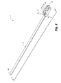
- Fig. 1 shows a one-piece fastener (1) having a housing (2) and strap (3).
- the strap has ratchet-shaped grooves (4) for locking the strap (3) when engaging the locking pawl (5) which is integrated in the housing (2).
- the centre axis of the guiding channel is extending parallel to the longitudinal axis of the strap, when the strap is engaged in the housing.
- the housing (2) of the fastener comprises a first side (6) having a first inner side surface (7) and an entry aperture (8), a second side (9) having a second inner side surface (10), a third side (11) having a third inner side surface (12) and an exit aperture (13), a fourth side (14) having a fourth inner side surface (15), a top side (16) with a top inner side surface (17), a bottom side (18) having a bottom inner side surface (19). Furthermore, the housing comprises a guiding channel (20) defined by the second and third side surfaces and the top and the bottom sides of the housing.
- the top side (16) of the housing (2) has a first aperture (21) for fastening the one-piece fastener (1) to a surface, e.g. a table, a ceiling or a wall, with a fastening means, such as bolts, screws or nails.
- a fastening means such as bolts, screws or nails.
- an entry aperture (8) is situated for guiding a first end of the strap (23) through the housing (2) for securing an element in the one-piece fastener.
- Fig. 2 shows a one-piece fastener (1), seen from the top of the housing, where the second side (9) and the top side (16) of the housing are shown.
- the first aperture (21) of the top side (16) may be provided with a recess, such as a counterbore or a countersinking (24).
- a recess such as a counterbore or a countersinking (24).
- Such counterbore (24) or countersinking ensures that the head of the fastening means (27) does not block the passage of the strap (3) when drawing the strap through the guide channel (20), since the head of the fastening means is conceiled in this recess.
- the sizes of the first and second apertures can, from one embodiment to another, be adapted to the different types of fastening means enabling the possibility for the worker to use different fastening means for different tasks, e.g. due to the fact that the size of the fastening means for gypsum is different than the fastening means for wood or concrete.
- the choice of a fastening means is dependent on the surface to which the one-piece fastener is supposed to fasten an element.
- the properties of the fastening means should also be compared to the weight of the element to be held by the one-piece fastener.
- the one-piece fastener may be made of polymer materials, and can withstand a weight of approx. 60 kg, and the fastening means should obviously have similar capabilities.
- the one-piece fastener is made of metal or nylon, e.g. nylon 6.6. Such element has the flexibility and strength that are necessary for the load needed.
- the one-piece fastener may also be made of any kind of polymer material.
- Fig. 3 shows a cross-sectional view along the line III-III of the one-piece fastener of Fig. 1 .
- Fig. 3 shows a fastening means (27) entering through the second aperture (26) of the bottom side of the housing (18).
- the difference in the diameter of the first aperture (21) and the second aperture (26) is 1-20 mm, preferably 2-18 mm, or most preferred 3-16 mm.
- the bottom side (18) has a second aperture (26) greater than the first aperture (21), in order to let the head of the fastening means (27) pass the second aperture (26) but to be received in the first aperture (21).
- the head of the fastening means (28) will draw the top side of the one-piece fastener towards the surface, e.g. a ceiling, a wall or table, onto which the one-piece fastener is to be fastened.
- the second aperture (26) has a greater extension than that shown in the drawings.
- the second aperture may have another shape, e.g. a square, a triangle, a trapeze or a pentagon etc.
- the bottom side does not exist so that the housing does not have a bottom side.
- the first aperture (21) is positioned with essentially equal distance to the entry and the exit aperture respectively.
- the one-piece fastener has been fasten to a ceiling and element such as a pipe has been bundled into the fastener, the secured element is subjected to its own weight and the strap (3) has its contact points to the housing at the entry aperture (8) and the exit aperture (13).
- the one-piece fastener is fastened to a ceiling and not a wall, the load from the element to be secured is distributed equally on each side of the head of the fastening means (28). If the surface is a ceiling, the element will automatically be positioned essentially just beneath the head of the fastening means, whereby the load is distributed in balance around the fastening means.
- the first inner bottom surface (19) of the bottom side (18) of the housing (10) and the inner top surface (17) of the top side (16) of the housing (2) defines a space (30).
- the strap (2) passes through the space (30) from the entry aperture (8) and out of the exit aperture (13) to secure an element.
- the top side (16) of the housing has two indentation (31) adapted to receive corresponding distance parts.
- Such distance parts can be used for a better fastening of the one-piece fastener to a surface near an obstacle, such as water pipes etc. It is necessary that the distance parts are arranged in a manner such that the risk of a dislocation of the distance parts is minimised.
- the one-piece fastener can secure all sorts of elements, such as wood plates, cables, wires, pipes, tubes, other electrical installations plants etc. Furthermore, the one-piece fastener can be fastened to any kind of surfaces, such as a table, a ceiling or a wall.
- the fastening means is disclosed as a screw, however, the fastening may be any kind of suitable fastening, such as a screw, a bolt or nails.
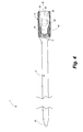
- Fig. 4 shows a longitudinal sectional view along the line IV-IV of Fig. 2 of the one-piece fastener.
- the housing (2) is provided with inwardly extending projections (29) for guiding the strap (3) in the housing along the longitudinal axis of the housing.
- inwardly extending projections (29) ensure a precise guiding of the strap.
- the inwardly extending projections (29) may be positioned opposing each other on the inner surfaces of the second and third sides of the housing.
- a one-piece fastener has a guide channel with projections (29) permitting that the strap (3) is led from the entry aperture (8) to the exit aperture (13).
- the guide channel decreases from the entry aperture (8) towards the exit aperture (13) in order to let the strap towards the locking pawl and the more narrow exit aperture (13) prevent the strap from sliding side to side.
- the fastening means can not force the strap (3) to disengage the locking pawl (5). If the fastening means is raised above the counterbore or countersinking (24) of the first aperture a pressure is subjected to a part of the strap opposing the head of the fastening means. Thus, the locking pawl (5) and the strap would be tightening their locking position.
- the entry aperture (8) is wider than the exit aperture (13), whereby it is easier for the worker to position the strap (3) in the housing so that a minimum of time and physical effort are spend whilst holding the often heavy element to be fastened.
- the exit aperture (13) is essentially the width of the strap, in order to control the engagement between the locking pawl of the housing (3) and the ratchet-shaped grooves of the strap.
- Fig. 5 shows the entry aperture (8) of the housing of the one-piece fastener and how the projections (29) and the locking pawl (5) are placed in relation to the surfaces.
- the strap (3) and the housing (2) may be produced as two separate pieces and subsequently joined by means of a gluing process, a welding process or the like.
Landscapes
- Engineering & Computer Science (AREA)
- Mechanical Engineering (AREA)
- General Engineering & Computer Science (AREA)
- Clamps And Clips (AREA)
Priority Applications (1)
| Application Number | Priority Date | Filing Date | Title |
|---|---|---|---|
| EP08002830A EP2090814A1 (de) | 2008-02-15 | 2008-02-15 | Einteiliger Befestiger |
Applications Claiming Priority (1)
| Application Number | Priority Date | Filing Date | Title |
|---|---|---|---|
| EP08002830A EP2090814A1 (de) | 2008-02-15 | 2008-02-15 | Einteiliger Befestiger |
Publications (1)
| Publication Number | Publication Date |
|---|---|
| EP2090814A1 true EP2090814A1 (de) | 2009-08-19 |
Family
ID=39473968
Family Applications (1)
| Application Number | Title | Priority Date | Filing Date |
|---|---|---|---|
| EP08002830A Withdrawn EP2090814A1 (de) | 2008-02-15 | 2008-02-15 | Einteiliger Befestiger |
Country Status (1)
| Country | Link |
|---|---|
| EP (1) | EP2090814A1 (de) |
Cited By (3)
| Publication number | Priority date | Publication date | Assignee | Title |
|---|---|---|---|---|
| GB2509909A (en) * | 2013-01-16 | 2014-07-23 | Lorne Entwistle | Connector including a strap |
| WO2020167142A1 (en) * | 2019-02-11 | 2020-08-20 | Timothy Dudek | A cable tie |
| RU2852876C1 (ru) * | 2025-06-25 | 2025-12-16 | Сергей Анатольевич Павлов | Хомут |
Citations (7)
| Publication number | Priority date | Publication date | Assignee | Title |
|---|---|---|---|---|
| US2915268A (en) * | 1955-05-17 | 1959-12-01 | Parisienne De Const Electromec | Ring clamp |
| GB2040352A (en) * | 1979-01-30 | 1980-08-28 | Legrand Sa | Cable tie |
| US4272047A (en) * | 1977-03-25 | 1981-06-09 | Boeing Commercial Airplane Company | Adjustable clamp |
| US4389754A (en) * | 1981-02-13 | 1983-06-28 | Nikko Kogyo Kabushiki Kaisha | Binding device |
| GB2185517A (en) * | 1986-01-22 | 1987-07-22 | Sekko Ab Oy | A clamp especially for an aerial bundled cable |
| WO1998038096A1 (en) * | 1997-02-27 | 1998-09-03 | Walkern Victoria Industries Limited | Fasteners |
| EP1818275A1 (de) | 2006-02-09 | 2007-08-15 | Panduit Corporation | Kabelbinder mit festen und drehbaren Verriegelungsmechanismen |
-
2008
- 2008-02-15 EP EP08002830A patent/EP2090814A1/de not_active Withdrawn
Patent Citations (7)
| Publication number | Priority date | Publication date | Assignee | Title |
|---|---|---|---|---|
| US2915268A (en) * | 1955-05-17 | 1959-12-01 | Parisienne De Const Electromec | Ring clamp |
| US4272047A (en) * | 1977-03-25 | 1981-06-09 | Boeing Commercial Airplane Company | Adjustable clamp |
| GB2040352A (en) * | 1979-01-30 | 1980-08-28 | Legrand Sa | Cable tie |
| US4389754A (en) * | 1981-02-13 | 1983-06-28 | Nikko Kogyo Kabushiki Kaisha | Binding device |
| GB2185517A (en) * | 1986-01-22 | 1987-07-22 | Sekko Ab Oy | A clamp especially for an aerial bundled cable |
| WO1998038096A1 (en) * | 1997-02-27 | 1998-09-03 | Walkern Victoria Industries Limited | Fasteners |
| EP1818275A1 (de) | 2006-02-09 | 2007-08-15 | Panduit Corporation | Kabelbinder mit festen und drehbaren Verriegelungsmechanismen |
Cited By (3)
| Publication number | Priority date | Publication date | Assignee | Title |
|---|---|---|---|---|
| GB2509909A (en) * | 2013-01-16 | 2014-07-23 | Lorne Entwistle | Connector including a strap |
| WO2020167142A1 (en) * | 2019-02-11 | 2020-08-20 | Timothy Dudek | A cable tie |
| RU2852876C1 (ru) * | 2025-06-25 | 2025-12-16 | Сергей Анатольевич Павлов | Хомут |
Similar Documents
| Publication | Publication Date | Title |
|---|---|---|
| EP3123580B1 (de) | Wiegenklemmhalterungsanordnung | |
| US4191334A (en) | Cable tie | |
| EP3396221B1 (de) | Flugzeug-kabelbefestigungsvorrichtung | |
| EP1369630B1 (de) | Kabelbinder | |
| JPH0419940Y2 (de) | ||
| US9958089B2 (en) | Lashing support spacer tie | |
| US7765650B2 (en) | Two-piece hose clamp and variable length clamp kit | |
| US10407985B2 (en) | Cradle clamp bracket assembly | |
| KR20140094591A (ko) | 물품의 표면 고정을 위한 결속체 | |
| US20110030175A1 (en) | Cording restraining means attachable to a tool | |
| USRE31689E (en) | Cable tie | |
| US10760715B1 (en) | Cable tie device | |
| KR20160141767A (ko) | 긴-치수 대상물 고정구 | |
| US9624016B1 (en) | Multi-surface cable tying device | |
| US20030070263A1 (en) | Cable tie style tail with improved grip | |
| CN219584879U (zh) | 一种箍紧带结构 | |
| WO2014151246A1 (en) | Cable lacing tie devices and methods of using the same | |
| JPH10147361A (ja) | バンドクランプ | |
| US5875522A (en) | Grommet and adjustable strap fastener assembly | |
| JPWO2015125220A1 (ja) | ロープ装着具 | |
| GB2356220A (en) | Fastening or securing device | |
| CN224205499U (zh) | 磁环固定装置及电磁兼容机组 | |
| WO2004054892A1 (en) | Strap | |
| JP6430817B2 (ja) | 取着体、取着具及び配線・配管材固定装置 | |
| FI76453C (fi) | Anordning foer fastspaenning av en laongstraeckt kropp. |
Legal Events
| Date | Code | Title | Description |
|---|---|---|---|
| PUAI | Public reference made under article 153(3) epc to a published international application that has entered the european phase |
Free format text: ORIGINAL CODE: 0009012 |
|
| AK | Designated contracting states |
Kind code of ref document: A1 Designated state(s): AT BE BG CH CY CZ DE DK EE ES FI FR GB GR HR HU IE IS IT LI LT LU LV MC MT NL NO PL PT RO SE SI SK TR |
|
| AX | Request for extension of the european patent |
Extension state: AL BA MK RS |
|
| AKX | Designation fees paid | ||
| REG | Reference to a national code |
Ref country code: DE Ref legal event code: 8566 |
|
| STAA | Information on the status of an ep patent application or granted ep patent |
Free format text: STATUS: THE APPLICATION IS DEEMED TO BE WITHDRAWN |
|
| 18D | Application deemed to be withdrawn |
Effective date: 20100220 |