EP2090816A1 - Joint arqué pour une selle de percement - Google Patents
Joint arqué pour une selle de percement Download PDFInfo
- Publication number
- EP2090816A1 EP2090816A1 EP08002938A EP08002938A EP2090816A1 EP 2090816 A1 EP2090816 A1 EP 2090816A1 EP 08002938 A EP08002938 A EP 08002938A EP 08002938 A EP08002938 A EP 08002938A EP 2090816 A1 EP2090816 A1 EP 2090816A1
- Authority
- EP
- European Patent Office
- Prior art keywords
- seal
- wall
- sealing
- base body
- sealing lip
- Prior art date
- Legal status (The legal status is an assumption and is not a legal conclusion. Google has not performed a legal analysis and makes no representation as to the accuracy of the status listed.)
- Granted
Links
Images



Classifications
-
- F—MECHANICAL ENGINEERING; LIGHTING; HEATING; WEAPONS; BLASTING
- F16—ENGINEERING ELEMENTS AND UNITS; GENERAL MEASURES FOR PRODUCING AND MAINTAINING EFFECTIVE FUNCTIONING OF MACHINES OR INSTALLATIONS; THERMAL INSULATION IN GENERAL
- F16L—PIPES; JOINTS OR FITTINGS FOR PIPES; SUPPORTS FOR PIPES, CABLES OR PROTECTIVE TUBING; MEANS FOR THERMAL INSULATION IN GENERAL
- F16L41/00—Branching pipes; Joining pipes to walls
- F16L41/04—Tapping pipe walls, i.e. making connections through the walls of pipes while they are carrying fluids; Fittings therefor
- F16L41/06—Tapping pipe walls, i.e. making connections through the walls of pipes while they are carrying fluids; Fittings therefor making use of attaching means embracing the pipe
-
- F—MECHANICAL ENGINEERING; LIGHTING; HEATING; WEAPONS; BLASTING
- F16—ENGINEERING ELEMENTS AND UNITS; GENERAL MEASURES FOR PRODUCING AND MAINTAINING EFFECTIVE FUNCTIONING OF MACHINES OR INSTALLATIONS; THERMAL INSULATION IN GENERAL
- F16J—PISTONS; CYLINDERS; SEALINGS
- F16J15/00—Sealings
- F16J15/02—Sealings between relatively-stationary surfaces
- F16J15/021—Sealings between relatively-stationary surfaces with elastic packing
- F16J15/022—Sealings between relatively-stationary surfaces with elastic packing characterised by structure or material
- F16J15/024—Sealings between relatively-stationary surfaces with elastic packing characterised by structure or material the packing being locally weakened in order to increase elasticity
- F16J15/025—Sealings between relatively-stationary surfaces with elastic packing characterised by structure or material the packing being locally weakened in order to increase elasticity and with at least one flexible lip
-
- F—MECHANICAL ENGINEERING; LIGHTING; HEATING; WEAPONS; BLASTING
- F16—ENGINEERING ELEMENTS AND UNITS; GENERAL MEASURES FOR PRODUCING AND MAINTAINING EFFECTIVE FUNCTIONING OF MACHINES OR INSTALLATIONS; THERMAL INSULATION IN GENERAL
- F16J—PISTONS; CYLINDERS; SEALINGS
- F16J15/00—Sealings
- F16J15/02—Sealings between relatively-stationary surfaces
- F16J15/06—Sealings between relatively-stationary surfaces with solid packing compressed between sealing surfaces
- F16J15/061—Sealings between relatively-stationary surfaces with solid packing compressed between sealing surfaces with positioning means
-
- F—MECHANICAL ENGINEERING; LIGHTING; HEATING; WEAPONS; BLASTING
- F16—ENGINEERING ELEMENTS AND UNITS; GENERAL MEASURES FOR PRODUCING AND MAINTAINING EFFECTIVE FUNCTIONING OF MACHINES OR INSTALLATIONS; THERMAL INSULATION IN GENERAL
- F16J—PISTONS; CYLINDERS; SEALINGS
- F16J15/00—Sealings
- F16J15/02—Sealings between relatively-stationary surfaces
- F16J15/06—Sealings between relatively-stationary surfaces with solid packing compressed between sealing surfaces
- F16J15/062—Sealings between relatively-stationary surfaces with solid packing compressed between sealing surfaces characterised by the geometry of the seat
-
- F—MECHANICAL ENGINEERING; LIGHTING; HEATING; WEAPONS; BLASTING
- F16—ENGINEERING ELEMENTS AND UNITS; GENERAL MEASURES FOR PRODUCING AND MAINTAINING EFFECTIVE FUNCTIONING OF MACHINES OR INSTALLATIONS; THERMAL INSULATION IN GENERAL
- F16L—PIPES; JOINTS OR FITTINGS FOR PIPES; SUPPORTS FOR PIPES, CABLES OR PROTECTIVE TUBING; MEANS FOR THERMAL INSULATION IN GENERAL
- F16L41/00—Branching pipes; Joining pipes to walls
- F16L41/04—Tapping pipe walls, i.e. making connections through the walls of pipes while they are carrying fluids; Fittings therefor
Definitions
- the invention relates to a seal for insertion between the outer wall of a pipe and the inner wall of a tapping clamp, comprising an elastically deformable annular base body, wherein the base body can be moved elastically from a starting shape in a Anpressgestalt and wherein the base body has at least a first circumferential sealing lip.
- Tapping clamps surround a pipe which is to be drilled.
- the pipes to be drilled carry gas or water and are not emptied during the drilling process. Therefore, it is necessary to seal the tapping point sufficiently so that the guided in the pipe to be drilled medium can not escape into the environment.
- the invention is therefore the object of a seal of the type mentioned in such a design and further that a sealing contact with the outer wall of a pipe to be drilled with a tapping clamp is easily implemented.
- a seal of the type mentioned is characterized in that the base body has a Vorkrümmung and limits a curved surface.
- a pre-curved main body allows the gasket to be applied to a curved outer wall of a pipe with virtually zero stress.
- a pre-curvature prevents the formation of compression of the body when the tapping clamp spends the body from its initial shape in the Anpressgestalt. Distortions can cause gaps. The formation of such gaps is effectively avoided by the inventive design. Furthermore, it is ensured that in the main body no voltage peaks occur when the tapping clamp presses the seal against the outer wall of the pipe. Consequently, the object mentioned above is achieved.
- the main body could be pre-curved in its initial shape such that the first sealing lip in its entirety essentially follows the outer wall of a tube and conforms to this gap with almost no gap and tension.
- This specific embodiment ensures that the seal can be pressed uniformly firmly against the outer wall of the pipe with only slight application of force, in order to ensure a sealing contact.
- the curved surface could be oppositely curved in their main directions.
- the curved surface need not be uniformly or symmetrically curved, but may be asymmetrically curved.
- Such a seal is suitable for use on deformed pipes, for example, have bulges or bulges.
- the curved surface could be formed as a saddle surface.
- Under a saddle surface is understood in the geometry of a control surface, which is opposite in its two main directions, namely anticlastic, curved.
- the name saddle surface has its origin in the word horse saddle or the saddle in the area, which also represents a transition between two mountains and two valleys.
- the formation of the surface as a saddle surface is particularly suitable for regularly cylindrically shaped tubes that show no deformations such as bumps or bulges. At such a uniform tube, the sealing lip nestles without formation of columns.
- the first sealing lip can be bent, a bendable sealing lip allows the sealing lip to be applied to two surfaces at the same time.
- a free end of the first sealing lip are associated with two sealing regions facing away from each other.
- a first sealing region of the outer wall of the tube and the second sealing region of the inner wall of the tapping clamp can be assigned.
- the first sealing region could be formed as a sealing edge and the second sealing region as a projecting bead.
- the sealing edge is due to an interference fit securely against the outer wall of the tube.
- a protruding bead ensures that the sealing lip only has to be bent slightly in order to come into contact with the inner wall of the tapping clamp.
- a projecting bead serve as a spacer, which prevents too tight pressing of the seal to the outer wall of the tube.
- the main body could have a second circumferential and bendable sealing lip.
- a second sealing flank can be created on the inner wall of the tapping sleeve.
- the main body has a third circumferential sealing lip, which defines a third sealing flank on the inner wall of the tapping clamp.
- the main body could have a fourth circumferential sealing lip, which bears against the outer wall of the tube.
- a fourth circumferential sealing lip which bears against the outer wall of the tube.
- the base body could have at least one device of a poka-yoke system.
- the Japanese term poka-yoke refers to a multi-element system that includes technical provisions for immediate fault detection and prevention.
- a poka-yoke system makes use of the key-lock principle to ensure secure positioning of the seal in the tapping saddle.
- the seals described here are particularly suitable for pipes with a diameter of 90 to 225 mm. Tubes with these diameters show a curvature of the outer wall, which require a curved seal for sealing engagement.
- An assembly could include a seal of the type described herein, a tube, and a tapping collar, the seal being positioned between the outer wall of the tube and the inner wall of the tapping collar.
- the seal could be partially received in a groove in the inner wall of the tapping saddle. The formation of a groove prevents the seal from slipping when the tapping saddle presses the seal against the outer wall of the pipe.
- the first sealing lip of the seal rests with a bead on the inner wall of the tapping clamp and with a sealing edge protruding from the bead on the outer wall of the tube. As a result, penetration of the medium guided in the tube is prevented in the groove.
- Two sealing lips of the seal could rest on the inner wall of the groove, preferably on the groove base, and two sealing lips on the outer wall of the tube. On the outer wall of the tube thereby two sealing edges are created. Within the groove bottom two sealing flanks are also created, so that a seal of the tapping point is ensured.
- the body of the seal could surround a drill.
- an annular space is created, which can fill with guided in the pipe medium.
- Fig. 1 shows a seal for insertion between the outer wall 1 of a pipe 2 and the inner wall 3 of a tapping clamp 4.
- the seal comprises an elastic body 5, wherein the base body 5 can be elastically brought from a starting shape in a Anpressgestalt and wherein the main body 5 at least a first circumferential Sealing lip 6 has.
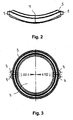
- the main body 5 has a pre-curvature and defines a curved surface 7.
- the main body 5 is precessed in its initial shape such that the first sealing lip 6 in its entirety substantially the outer wall. 1 a tube 2 follows and clings almost gap and stress-free to this.
- the curved surface 7 is curved in opposite directions in its main directions.
- the curved surface 7 is formed as a saddle surface.
- the main body 5 has a device 8 of a Poka-Yoke system.
- the device 8 comprises semicircular protuberances which protrude in the radial direction from the main body 5. This device 8 ensures error-free positioning of the seal in the tapping sleeve 4.
- Fig. 2 shows the seal according to Fig. 1 in a side view.
- Fig. 3 shows the seal according to Fig. 1 in a top view.
- the base body 5 defines a curved surface 7.
- the device 8 can be seen, which has semicircular protuberances which protrude in the radial direction from the main body 5.
- Fig. 4 shows a section of the base body 5, which is inserted in a groove 9 in the inner wall 3 of the tapping clamp 4.
- the main body 5 has a first circumferential sealing lip 6, which is bendable.
- a free end 10 of the first sealing lip 6 are assigned two opposing sealing regions.
- the first sealing region is designed as a sealing edge 11 and the second sealing region as a projecting bead 12.
- the main body 5 has a second circumferential and bendable sealing lip 13.
- Fig. 5 and 6 show a sectional view of the main body 5 in different sectional planes.
- Fig. 5 and Fig. 6 show the third circumferential sealing lip 14 and the fourth circumferential sealing lip 15. Further show the Figures 5 and 6 the first bendable sealing lip 6, which has two opposite sealing regions at its free end 10.
- the first sealing region is designed as a sealing edge 11 and the second sealing region as a projecting bead 12.
- Fig. 7 shows an assembly comprising a seal, a tube 2 and a tapping sleeve 4.
- the seal between the outer wall 1 of the tube 2 and the inner wall 3 of the tapping clamp 4 is positioned.
- the seal is partially received in a groove 9 in the inner wall 3 of the tapping clamp 4.
- the first sealing lip 6 of the seal abuts with a bead 12 on the inner wall of the tapping clamp 4. With the sealing edge 11, the free end 10 of the sealing lip 6 abuts against the outer wall 1 of the tube 2.
- Two sealing lips 13, 14 of the seal lie on the groove bottom of the groove 9 and two sealing lips 6 and 15 abut against the outer wall 1 of the tube 2.
- the main body 5 of the seal surrounds a drill 16.
Landscapes
- Engineering & Computer Science (AREA)
- General Engineering & Computer Science (AREA)
- Mechanical Engineering (AREA)
- Physics & Mathematics (AREA)
- Geometry (AREA)
- Gasket Seals (AREA)
- Dowels (AREA)
- Earth Drilling (AREA)
- Clamps And Clips (AREA)
- Lift Valve (AREA)
- Sealing Devices (AREA)
- Diaphragms For Electromechanical Transducers (AREA)
Priority Applications (5)
| Application Number | Priority Date | Filing Date | Title |
|---|---|---|---|
| DK08002938.2T DK2090816T3 (da) | 2008-02-18 | 2008-02-18 | Krum tætning til en anboringsbøjle |
| EP08002938A EP2090816B1 (fr) | 2008-02-18 | 2008-02-18 | Joint arqué pour une selle de percement |
| SI200830056T SI2090816T1 (sl) | 2008-02-18 | 2008-02-18 | Ukrivljeno tesnilo za navrtno objemko |
| DE502008000773T DE502008000773D1 (de) | 2008-02-18 | 2008-02-18 | Gekrümmte Dichtung für eine Anbohrschelle |
| AT08002938T ATE470816T1 (de) | 2008-02-18 | 2008-02-18 | Gekrümmte dichtung für eine anbohrschelle |
Applications Claiming Priority (1)
| Application Number | Priority Date | Filing Date | Title |
|---|---|---|---|
| EP08002938A EP2090816B1 (fr) | 2008-02-18 | 2008-02-18 | Joint arqué pour une selle de percement |
Publications (2)
| Publication Number | Publication Date |
|---|---|
| EP2090816A1 true EP2090816A1 (fr) | 2009-08-19 |
| EP2090816B1 EP2090816B1 (fr) | 2010-06-09 |
Family
ID=39362272
Family Applications (1)
| Application Number | Title | Priority Date | Filing Date |
|---|---|---|---|
| EP08002938A Not-in-force EP2090816B1 (fr) | 2008-02-18 | 2008-02-18 | Joint arqué pour une selle de percement |
Country Status (5)
| Country | Link |
|---|---|
| EP (1) | EP2090816B1 (fr) |
| AT (1) | ATE470816T1 (fr) |
| DE (1) | DE502008000773D1 (fr) |
| DK (1) | DK2090816T3 (fr) |
| SI (1) | SI2090816T1 (fr) |
Cited By (3)
| Publication number | Priority date | Publication date | Assignee | Title |
|---|---|---|---|---|
| EP2829782A1 (fr) * | 2013-07-23 | 2015-01-28 | Georg Fischer Rohrleitungssysteme AG | Selle pour un raccord de dérivation |
| GB2533483A (en) * | 2014-12-18 | 2016-06-22 | Skf Ab | Plug valve seal |
| WO2017144129A1 (fr) * | 2016-02-22 | 2017-08-31 | Federal-Mogul Sealing Systems Gmbh | Système d'étanchéité pour un composant de moteur et composant de moteur pourvu de ce système d'étanchéité |
Citations (3)
| Publication number | Priority date | Publication date | Assignee | Title |
|---|---|---|---|---|
| US20020000719A1 (en) * | 1999-01-22 | 2002-01-03 | Donald R. Kunsman | Pipe branch fitting |
| DE20305736U1 (de) | 2003-04-04 | 2003-06-05 | Hawle Armaturen GmbH, 83395 Freilassing | Anbohrarmatur |
| US20070205004A1 (en) * | 2005-09-07 | 2007-09-06 | Noveon, Inc. | System And Method Of Assembly Of CPVC Fire Sprinkler System Employing Mechanical Couplings And Supports |
-
2008
- 2008-02-18 AT AT08002938T patent/ATE470816T1/de active
- 2008-02-18 DE DE502008000773T patent/DE502008000773D1/de active Active
- 2008-02-18 DK DK08002938.2T patent/DK2090816T3/da active
- 2008-02-18 SI SI200830056T patent/SI2090816T1/sl unknown
- 2008-02-18 EP EP08002938A patent/EP2090816B1/fr not_active Not-in-force
Patent Citations (3)
| Publication number | Priority date | Publication date | Assignee | Title |
|---|---|---|---|---|
| US20020000719A1 (en) * | 1999-01-22 | 2002-01-03 | Donald R. Kunsman | Pipe branch fitting |
| DE20305736U1 (de) | 2003-04-04 | 2003-06-05 | Hawle Armaturen GmbH, 83395 Freilassing | Anbohrarmatur |
| US20070205004A1 (en) * | 2005-09-07 | 2007-09-06 | Noveon, Inc. | System And Method Of Assembly Of CPVC Fire Sprinkler System Employing Mechanical Couplings And Supports |
Cited By (5)
| Publication number | Priority date | Publication date | Assignee | Title |
|---|---|---|---|---|
| EP2829782A1 (fr) * | 2013-07-23 | 2015-01-28 | Georg Fischer Rohrleitungssysteme AG | Selle pour un raccord de dérivation |
| US9255641B2 (en) | 2013-07-23 | 2016-02-09 | Georg Fischer Rohrleitungssysteme Ag | Saddle for a branch connection |
| GB2533483A (en) * | 2014-12-18 | 2016-06-22 | Skf Ab | Plug valve seal |
| GB2533483B (en) * | 2014-12-18 | 2017-06-07 | Skf Ab | Plug valve seal |
| WO2017144129A1 (fr) * | 2016-02-22 | 2017-08-31 | Federal-Mogul Sealing Systems Gmbh | Système d'étanchéité pour un composant de moteur et composant de moteur pourvu de ce système d'étanchéité |
Also Published As
| Publication number | Publication date |
|---|---|
| DE502008000773D1 (de) | 2010-07-22 |
| ATE470816T1 (de) | 2010-06-15 |
| SI2090816T1 (sl) | 2010-09-30 |
| DK2090816T3 (da) | 2010-09-13 |
| EP2090816B1 (fr) | 2010-06-09 |
Similar Documents
| Publication | Publication Date | Title |
|---|---|---|
| DE2021652C3 (de) | Rohrverbindung | |
| DE3531540C2 (de) | Eine die Trennung verhindernde Rohrverbindung | |
| DE102014101795B4 (de) | Quetschverbindung mit entgegengesetzt gerichteten Zacken | |
| DE102010016557A1 (de) | Rohr- oder Kabeldurchführung zur dichten Durchführung wenigstens eines Rohres oder wenigstens eines Kabels durch eine Wand- oder Deckenplatte | |
| DE69514552T2 (de) | Rohrkupplung | |
| DE3427094A1 (de) | Elektrisch isolierendes kupplungsstueck | |
| EP2090816B1 (fr) | Joint arqué pour une selle de percement | |
| EP0133627B2 (fr) | Dispositif pour la fixation étanche d'un tuyau dans l'ouverture d'une plaque de fixation de tuyaux | |
| DE2817438A1 (de) | Rohrverschraubung, insbesondere fuer unter druck stehende kraftstoffleitungen und oelleitungen in kraftfahrzeugen | |
| DE2223417A1 (de) | Schraubverbindung mit dichtungsring | |
| DE102007021175B3 (de) | Metallisch abdichtende Verbindungsverschraubung | |
| DE102023114933A1 (de) | Wiedermontierbare Schneidringverschraubung | |
| DE102019100897A1 (de) | Pass- und Ausbaustück für Rohrleitungen | |
| DE19946133A1 (de) | Lippendichtring | |
| DE2600621C3 (de) | Gewindelose Verbindung für Rohre und Verfahren zu ihrer Herstellung | |
| DE20121607U1 (de) | Anschlussvorrichtung für einen ringgewellten Metallschlauch | |
| DE112017005493T5 (de) | Dichtungsanordnung, Dichtungsverfahren und Kupplung mit der Dichtungsanordnung | |
| AT391538B (de) | Anschluss- bzw. verbindungsstueck aus einem einzigen stueck, fuer die direkte verbindung von glatten rohren an gewindeanschluessen | |
| EP1118811A2 (fr) | Conduite flexible avec un dispositif de raccordement sur au moins une extrémité | |
| DE19943473B4 (de) | Dichtungsvorrichtung | |
| CH657436A5 (de) | Verschraubungssystem. | |
| DE3503265A1 (de) | Federscheiben-kompressionsfittingeinheit | |
| DE2039256A1 (de) | Rohrverbindung | |
| DE102008058958A1 (de) | Rohrverbindungsanordnung für ein Antriebsaggregat eines Fahrzeugs und Brennstoffzellensystem | |
| EP1086329B1 (fr) | Raccord visse a garniture d'etancheite axiale |
Legal Events
| Date | Code | Title | Description |
|---|---|---|---|
| PUAI | Public reference made under article 153(3) epc to a published international application that has entered the european phase |
Free format text: ORIGINAL CODE: 0009012 |
|
| 17P | Request for examination filed |
Effective date: 20081007 |
|
| AK | Designated contracting states |
Kind code of ref document: A1 Designated state(s): AT BE BG CH CY CZ DE DK EE ES FI FR GB GR HR HU IE IS IT LI LT LU LV MC MT NL NO PL PT RO SE SI SK TR |
|
| AX | Request for extension of the european patent |
Extension state: AL BA MK RS |
|
| GRAP | Despatch of communication of intention to grant a patent |
Free format text: ORIGINAL CODE: EPIDOSNIGR1 |
|
| GRAS | Grant fee paid |
Free format text: ORIGINAL CODE: EPIDOSNIGR3 |
|
| AKX | Designation fees paid |
Designated state(s): AT BE BG CH CY CZ DE DK EE ES FI FR GB GR HR HU IE IS IT LI LT LU LV MC MT NL NO PL PT RO SE SI SK TR |
|
| GRAA | (expected) grant |
Free format text: ORIGINAL CODE: 0009210 |
|
| AK | Designated contracting states |
Kind code of ref document: B1 Designated state(s): AT BE BG CH CY CZ DE DK EE ES FI FR GB GR HR HU IE IS IT LI LT LU LV MC MT NL NO PL PT RO SE SI SK TR |
|
| REG | Reference to a national code |
Ref country code: CH Ref legal event code: EP |
|
| REG | Reference to a national code |
Ref country code: IE Ref legal event code: FG4D Free format text: LANGUAGE OF EP DOCUMENT: GERMAN |
|
| REF | Corresponds to: |
Ref document number: 502008000773 Country of ref document: DE Date of ref document: 20100722 Kind code of ref document: P |
|
| REG | Reference to a national code |
Ref country code: NL Ref legal event code: T3 |
|
| REG | Reference to a national code |
Ref country code: DK Ref legal event code: T3 |
|
| PG25 | Lapsed in a contracting state [announced via postgrant information from national office to epo] |
Ref country code: NO Free format text: LAPSE BECAUSE OF FAILURE TO SUBMIT A TRANSLATION OF THE DESCRIPTION OR TO PAY THE FEE WITHIN THE PRESCRIBED TIME-LIMIT Effective date: 20100909 Ref country code: LT Free format text: LAPSE BECAUSE OF FAILURE TO SUBMIT A TRANSLATION OF THE DESCRIPTION OR TO PAY THE FEE WITHIN THE PRESCRIBED TIME-LIMIT Effective date: 20100609 Ref country code: SE Free format text: LAPSE BECAUSE OF FAILURE TO SUBMIT A TRANSLATION OF THE DESCRIPTION OR TO PAY THE FEE WITHIN THE PRESCRIBED TIME-LIMIT Effective date: 20100609 |
|
| LTIE | Lt: invalidation of european patent or patent extension |
Effective date: 20100609 |
|
| PG25 | Lapsed in a contracting state [announced via postgrant information from national office to epo] |
Ref country code: HR Free format text: LAPSE BECAUSE OF FAILURE TO SUBMIT A TRANSLATION OF THE DESCRIPTION OR TO PAY THE FEE WITHIN THE PRESCRIBED TIME-LIMIT Effective date: 20100609 Ref country code: LV Free format text: LAPSE BECAUSE OF FAILURE TO SUBMIT A TRANSLATION OF THE DESCRIPTION OR TO PAY THE FEE WITHIN THE PRESCRIBED TIME-LIMIT Effective date: 20100609 Ref country code: FI Free format text: LAPSE BECAUSE OF FAILURE TO SUBMIT A TRANSLATION OF THE DESCRIPTION OR TO PAY THE FEE WITHIN THE PRESCRIBED TIME-LIMIT Effective date: 20100609 |
|
| PG25 | Lapsed in a contracting state [announced via postgrant information from national office to epo] |
Ref country code: PL Free format text: LAPSE BECAUSE OF FAILURE TO SUBMIT A TRANSLATION OF THE DESCRIPTION OR TO PAY THE FEE WITHIN THE PRESCRIBED TIME-LIMIT Effective date: 20100609 Ref country code: CY Free format text: LAPSE BECAUSE OF FAILURE TO SUBMIT A TRANSLATION OF THE DESCRIPTION OR TO PAY THE FEE WITHIN THE PRESCRIBED TIME-LIMIT Effective date: 20100616 |
|
| REG | Reference to a national code |
Ref country code: IE Ref legal event code: FD4D |
|
| PG25 | Lapsed in a contracting state [announced via postgrant information from national office to epo] |
Ref country code: IE Free format text: LAPSE BECAUSE OF FAILURE TO SUBMIT A TRANSLATION OF THE DESCRIPTION OR TO PAY THE FEE WITHIN THE PRESCRIBED TIME-LIMIT Effective date: 20100609 Ref country code: EE Free format text: LAPSE BECAUSE OF FAILURE TO SUBMIT A TRANSLATION OF THE DESCRIPTION OR TO PAY THE FEE WITHIN THE PRESCRIBED TIME-LIMIT Effective date: 20100609 |
|
| PG25 | Lapsed in a contracting state [announced via postgrant information from national office to epo] |
Ref country code: SK Free format text: LAPSE BECAUSE OF FAILURE TO SUBMIT A TRANSLATION OF THE DESCRIPTION OR TO PAY THE FEE WITHIN THE PRESCRIBED TIME-LIMIT Effective date: 20100609 Ref country code: RO Free format text: LAPSE BECAUSE OF FAILURE TO SUBMIT A TRANSLATION OF THE DESCRIPTION OR TO PAY THE FEE WITHIN THE PRESCRIBED TIME-LIMIT Effective date: 20100609 Ref country code: IS Free format text: LAPSE BECAUSE OF FAILURE TO SUBMIT A TRANSLATION OF THE DESCRIPTION OR TO PAY THE FEE WITHIN THE PRESCRIBED TIME-LIMIT Effective date: 20101009 Ref country code: CZ Free format text: LAPSE BECAUSE OF FAILURE TO SUBMIT A TRANSLATION OF THE DESCRIPTION OR TO PAY THE FEE WITHIN THE PRESCRIBED TIME-LIMIT Effective date: 20100609 |
|
| PLBE | No opposition filed within time limit |
Free format text: ORIGINAL CODE: 0009261 |
|
| STAA | Information on the status of an ep patent application or granted ep patent |
Free format text: STATUS: NO OPPOSITION FILED WITHIN TIME LIMIT |
|
| PG25 | Lapsed in a contracting state [announced via postgrant information from national office to epo] |
Ref country code: GR Free format text: LAPSE BECAUSE OF FAILURE TO SUBMIT A TRANSLATION OF THE DESCRIPTION OR TO PAY THE FEE WITHIN THE PRESCRIBED TIME-LIMIT Effective date: 20100910 |
|
| REG | Reference to a national code |
Ref country code: DE Ref legal event code: R097 Ref document number: 502008000773 Country of ref document: DE Effective date: 20110309 |
|
| BERE | Be: lapsed |
Owner name: CARL FREUDENBERG K.G. Effective date: 20110228 |
|
| PG25 | Lapsed in a contracting state [announced via postgrant information from national office to epo] |
Ref country code: MC Free format text: LAPSE BECAUSE OF NON-PAYMENT OF DUE FEES Effective date: 20110228 |
|
| PG25 | Lapsed in a contracting state [announced via postgrant information from national office to epo] |
Ref country code: BE Free format text: LAPSE BECAUSE OF NON-PAYMENT OF DUE FEES Effective date: 20110228 |
|
| PG25 | Lapsed in a contracting state [announced via postgrant information from national office to epo] |
Ref country code: MT Free format text: LAPSE BECAUSE OF FAILURE TO SUBMIT A TRANSLATION OF THE DESCRIPTION OR TO PAY THE FEE WITHIN THE PRESCRIBED TIME-LIMIT Effective date: 20100609 |
|
| PGFP | Annual fee paid to national office [announced via postgrant information from national office to epo] |
Ref country code: IT Payment date: 20120224 Year of fee payment: 5 |
|
| REG | Reference to a national code |
Ref country code: CH Ref legal event code: PL |
|
| PG25 | Lapsed in a contracting state [announced via postgrant information from national office to epo] |
Ref country code: LI Free format text: LAPSE BECAUSE OF NON-PAYMENT OF DUE FEES Effective date: 20120229 Ref country code: CH Free format text: LAPSE BECAUSE OF NON-PAYMENT OF DUE FEES Effective date: 20120229 |
|
| PGFP | Annual fee paid to national office [announced via postgrant information from national office to epo] |
Ref country code: DK Payment date: 20130221 Year of fee payment: 6 Ref country code: GB Payment date: 20130221 Year of fee payment: 6 Ref country code: FR Payment date: 20130314 Year of fee payment: 6 |
|
| PG25 | Lapsed in a contracting state [announced via postgrant information from national office to epo] |
Ref country code: LU Free format text: LAPSE BECAUSE OF NON-PAYMENT OF DUE FEES Effective date: 20110218 |
|
| PGFP | Annual fee paid to national office [announced via postgrant information from national office to epo] |
Ref country code: NL Payment date: 20130221 Year of fee payment: 6 Ref country code: SI Payment date: 20130123 Year of fee payment: 6 |
|
| PGFP | Annual fee paid to national office [announced via postgrant information from national office to epo] |
Ref country code: AT Payment date: 20130225 Year of fee payment: 6 |
|
| PG25 | Lapsed in a contracting state [announced via postgrant information from national office to epo] |
Ref country code: PT Free format text: LAPSE BECAUSE OF NON-PAYMENT OF DUE FEES Effective date: 20100609 |
|
| PGFP | Annual fee paid to national office [announced via postgrant information from national office to epo] |
Ref country code: DE Payment date: 20130408 Year of fee payment: 6 |
|
| PG25 | Lapsed in a contracting state [announced via postgrant information from national office to epo] |
Ref country code: TR Free format text: LAPSE BECAUSE OF FAILURE TO SUBMIT A TRANSLATION OF THE DESCRIPTION OR TO PAY THE FEE WITHIN THE PRESCRIBED TIME-LIMIT Effective date: 20100609 Ref country code: BG Free format text: LAPSE BECAUSE OF FAILURE TO SUBMIT A TRANSLATION OF THE DESCRIPTION OR TO PAY THE FEE WITHIN THE PRESCRIBED TIME-LIMIT Effective date: 20100909 |
|
| PG25 | Lapsed in a contracting state [announced via postgrant information from national office to epo] |
Ref country code: ES Free format text: LAPSE BECAUSE OF FAILURE TO SUBMIT A TRANSLATION OF THE DESCRIPTION OR TO PAY THE FEE WITHIN THE PRESCRIBED TIME-LIMIT Effective date: 20100920 Ref country code: HU Free format text: LAPSE BECAUSE OF FAILURE TO SUBMIT A TRANSLATION OF THE DESCRIPTION OR TO PAY THE FEE WITHIN THE PRESCRIBED TIME-LIMIT Effective date: 20100609 |
|
| REG | Reference to a national code |
Ref country code: DE Ref legal event code: R119 Ref document number: 502008000773 Country of ref document: DE |
|
| REG | Reference to a national code |
Ref country code: NL Ref legal event code: V1 Effective date: 20140901 |
|
| REG | Reference to a national code |
Ref country code: DK Ref legal event code: EBP Effective date: 20140228 |
|
| REG | Reference to a national code |
Ref country code: AT Ref legal event code: MM01 Ref document number: 470816 Country of ref document: AT Kind code of ref document: T Effective date: 20140218 |
|
| GBPC | Gb: european patent ceased through non-payment of renewal fee |
Effective date: 20140218 |
|
| PG25 | Lapsed in a contracting state [announced via postgrant information from national office to epo] |
Ref country code: NL Free format text: LAPSE BECAUSE OF NON-PAYMENT OF DUE FEES Effective date: 20140901 |
|
| REG | Reference to a national code |
Ref country code: FR Ref legal event code: ST Effective date: 20141031 |
|
| REG | Reference to a national code |
Ref country code: DE Ref legal event code: R119 Ref document number: 502008000773 Country of ref document: DE Effective date: 20140902 |
|
| PG25 | Lapsed in a contracting state [announced via postgrant information from national office to epo] |
Ref country code: SI Free format text: LAPSE BECAUSE OF NON-PAYMENT OF DUE FEES Effective date: 20140219 Ref country code: AT Free format text: LAPSE BECAUSE OF NON-PAYMENT OF DUE FEES Effective date: 20140218 |
|
| REG | Reference to a national code |
Ref country code: SI Ref legal event code: KO00 Effective date: 20141007 |
|
| PG25 | Lapsed in a contracting state [announced via postgrant information from national office to epo] |
Ref country code: GB Free format text: LAPSE BECAUSE OF NON-PAYMENT OF DUE FEES Effective date: 20140218 Ref country code: DE Free format text: LAPSE BECAUSE OF NON-PAYMENT OF DUE FEES Effective date: 20140902 Ref country code: DK Free format text: LAPSE BECAUSE OF NON-PAYMENT OF DUE FEES Effective date: 20140228 Ref country code: FR Free format text: LAPSE BECAUSE OF NON-PAYMENT OF DUE FEES Effective date: 20140228 |
|
| PG25 | Lapsed in a contracting state [announced via postgrant information from national office to epo] |
Ref country code: IT Free format text: LAPSE BECAUSE OF NON-PAYMENT OF DUE FEES Effective date: 20140218 |