EP2090824A2 - Gewächshauslicht, Gewächshauslichtsystem und Verfahren zum Ändern des Strahlenmusters eines Gewächshauslichts - Google Patents
Gewächshauslicht, Gewächshauslichtsystem und Verfahren zum Ändern des Strahlenmusters eines Gewächshauslichts Download PDFInfo
- Publication number
- EP2090824A2 EP2090824A2 EP20090152454 EP09152454A EP2090824A2 EP 2090824 A2 EP2090824 A2 EP 2090824A2 EP 20090152454 EP20090152454 EP 20090152454 EP 09152454 A EP09152454 A EP 09152454A EP 2090824 A2 EP2090824 A2 EP 2090824A2
- Authority
- EP
- European Patent Office
- Prior art keywords
- light
- greenhouse
- frame
- reflector
- light source
- Prior art date
- Legal status (The legal status is an assumption and is not a legal conclusion. Google has not performed a legal analysis and makes no representation as to the accuracy of the status listed.)
- Granted
Links
- 238000000034 method Methods 0.000 title claims abstract description 11
- 230000005855 radiation Effects 0.000 title claims abstract description 10
- 230000005670 electromagnetic radiation Effects 0.000 claims abstract description 8
- 230000003287 optical effect Effects 0.000 claims description 4
- DGAQECJNVWCQMB-PUAWFVPOSA-M Ilexoside XXIX Chemical compound C[C@@H]1CC[C@@]2(CC[C@@]3(C(=CC[C@H]4[C@]3(CC[C@@H]5[C@@]4(CC[C@@H](C5(C)C)OS(=O)(=O)[O-])C)C)[C@@H]2[C@]1(C)O)C)C(=O)O[C@H]6[C@@H]([C@H]([C@@H]([C@H](O6)CO)O)O)O.[Na+] DGAQECJNVWCQMB-PUAWFVPOSA-M 0.000 claims description 3
- QSHDDOUJBYECFT-UHFFFAOYSA-N mercury Chemical compound [Hg] QSHDDOUJBYECFT-UHFFFAOYSA-N 0.000 claims description 3
- 229910052753 mercury Inorganic materials 0.000 claims description 3
- 229910052708 sodium Inorganic materials 0.000 claims description 3
- 239000011734 sodium Substances 0.000 claims description 3
- 241000196324 Embryophyta Species 0.000 description 10
- 230000001419 dependent effect Effects 0.000 description 2
- 239000002689 soil Substances 0.000 description 2
- 235000002566 Capsicum Nutrition 0.000 description 1
- 235000009849 Cucumis sativus Nutrition 0.000 description 1
- 240000008067 Cucumis sativus Species 0.000 description 1
- 235000007688 Lycopersicon esculentum Nutrition 0.000 description 1
- 241000758706 Piperaceae Species 0.000 description 1
- 240000003768 Solanum lycopersicum Species 0.000 description 1
- 229910000831 Steel Inorganic materials 0.000 description 1
- XAGFODPZIPBFFR-UHFFFAOYSA-N aluminium Chemical compound [Al] XAGFODPZIPBFFR-UHFFFAOYSA-N 0.000 description 1
- 229910052782 aluminium Inorganic materials 0.000 description 1
- 239000004411 aluminium Substances 0.000 description 1
- 238000001816 cooling Methods 0.000 description 1
- 235000013399 edible fruits Nutrition 0.000 description 1
- 238000004519 manufacturing process Methods 0.000 description 1
- 230000029553 photosynthesis Effects 0.000 description 1
- 238000010672 photosynthesis Methods 0.000 description 1
- 239000010959 steel Substances 0.000 description 1
- 235000013311 vegetables Nutrition 0.000 description 1
Images


Classifications
-
- F—MECHANICAL ENGINEERING; LIGHTING; HEATING; WEAPONS; BLASTING
- F21—LIGHTING
- F21V—FUNCTIONAL FEATURES OR DETAILS OF LIGHTING DEVICES OR SYSTEMS THEREOF; STRUCTURAL COMBINATIONS OF LIGHTING DEVICES WITH OTHER ARTICLES, NOT OTHERWISE PROVIDED FOR
- F21V14/00—Controlling the distribution of the light emitted by adjustment of elements
- F21V14/02—Controlling the distribution of the light emitted by adjustment of elements by movement of light sources
-
- A—HUMAN NECESSITIES
- A01—AGRICULTURE; FORESTRY; ANIMAL HUSBANDRY; HUNTING; TRAPPING; FISHING
- A01G—HORTICULTURE; CULTIVATION OF VEGETABLES, FLOWERS, RICE, FRUIT, VINES, HOPS OR SEAWEED; FORESTRY; WATERING
- A01G9/00—Cultivation in receptacles, forcing-frames or greenhouses; Edging for beds, lawn or the like
- A01G9/24—Devices or systems for heating, ventilating, regulating temperature, illuminating, or watering, in greenhouses, forcing-frames, or the like
- A01G9/249—Lighting means
-
- F—MECHANICAL ENGINEERING; LIGHTING; HEATING; WEAPONS; BLASTING
- F21—LIGHTING
- F21V—FUNCTIONAL FEATURES OR DETAILS OF LIGHTING DEVICES OR SYSTEMS THEREOF; STRUCTURAL COMBINATIONS OF LIGHTING DEVICES WITH OTHER ARTICLES, NOT OTHERWISE PROVIDED FOR
- F21V19/00—Fastening of light sources or lamp holders
- F21V19/02—Fastening of light sources or lamp holders with provision for adjustment, e.g. for focusing
-
- F—MECHANICAL ENGINEERING; LIGHTING; HEATING; WEAPONS; BLASTING
- F21—LIGHTING
- F21S—NON-PORTABLE LIGHTING DEVICES; SYSTEMS THEREOF; VEHICLE LIGHTING DEVICES SPECIALLY ADAPTED FOR VEHICLE EXTERIORS
- F21S8/00—Lighting devices intended for fixed installation
- F21S8/04—Lighting devices intended for fixed installation intended only for mounting on a ceiling or the like overhead structures
- F21S8/06—Lighting devices intended for fixed installation intended only for mounting on a ceiling or the like overhead structures by suspension
- F21S8/061—Lighting devices intended for fixed installation intended only for mounting on a ceiling or the like overhead structures by suspension with a non-rigid pendant, i.e. a cable, wire or chain
-
- F—MECHANICAL ENGINEERING; LIGHTING; HEATING; WEAPONS; BLASTING
- F21—LIGHTING
- F21V—FUNCTIONAL FEATURES OR DETAILS OF LIGHTING DEVICES OR SYSTEMS THEREOF; STRUCTURAL COMBINATIONS OF LIGHTING DEVICES WITH OTHER ARTICLES, NOT OTHERWISE PROVIDED FOR
- F21V21/00—Supporting, suspending, or attaching arrangements for lighting devices; Hand grips
- F21V21/14—Adjustable mountings
- F21V21/15—Adjustable mountings specially adapted for power operation, e.g. by remote control
-
- F—MECHANICAL ENGINEERING; LIGHTING; HEATING; WEAPONS; BLASTING
- F21—LIGHTING
- F21Y—INDEXING SCHEME ASSOCIATED WITH SUBCLASSES F21K, F21L, F21S and F21V, RELATING TO THE FORM OR THE KIND OF THE LIGHT SOURCES OR OF THE COLOUR OF THE LIGHT EMITTED
- F21Y2115/00—Light-generating elements of semiconductor light sources
- F21Y2115/10—Light-emitting diodes [LED]
Definitions
- the invention relates to a greenhouse light, a greenhouse light system and a method for altering the radiation pattern of a greenhouse light according to the preambles of the independent claims presented below.
- the above-mentioned factors which have an influence on the productivity, may be adjusted in a controlled manner.
- the temperature of the greenhouse and the humidity of the air and soil are selected according to the cultivated plant species.
- lighting is used in the greenhouse, the luminosity of which lighting can be adjusted.
- the lights typically use light sources, the spectre of which is such that the light produced by the light sources promotes the photosynthesis of the plants.
- Greenhouse lighting has traditionally been carried out using overhead lights, which are attached to the ceiling of the greenhouse and which radiate downwards, in which lights a stationary reflector, which is integrated into the light frame, has been used in order to achieve the desired light beam.
- Publication US 6312139 presents an overhead light system, where the lights are moveable in the vertical direction. With the presented solution the lights can be brought close to the growth, regardless of the height of the growth. Thus for example in the growing stage of the plant, the overhead lights can be moved so that they are always at a desired distance from the top part of the growth.
- Publication US 5095414 presents a greenhouse light, where the reflector of the light can be turned around the longitudinal axis of the bulb and thus the light beam of the light can be directed in different directions.
- the problem with the overhead light is that with them sufficient light can be produced only to the top part of the growth. If the luminosity of the overhead light were to be increased so much that it would suffice also for the lower parts of the growth, there would be a danger that the temperature would rise too high in the top parts of the growth. The temperature rise could thus result in damage in the plant. Additionally the problem with the overhead lights is that they function as shades for natural light and thus shade the growth.
- intermediate lights can also be used in greenhouses in addition to or instead of overhead lights, which intermediate lights are placed lower between the rows of the growth.
- the intermediate light typically has no reflector at all and the elongated light source is arranged in a vertical position, whereby the light radiates omnidirectionally.
- the task of the intermediate light is to give light especially to the middle and lower parts of the growth.
- the use of an intermediate light is necessary for example when cultivating cucumbers, tomatoes or peppers, since the top part of the growth in these cases heavily shades the lower parts of the growth.
- a typical greenhouse light according to the invention comprises a light frame, a light source fitted in connection with the first end of the light frame and a reflector arranged at a distance from the light source for reflecting the electromagnetic radiation emitted by the light source.
- the light frame is arranged to be turnable in relation to the reflector, so that the distance between the light source and the reflector can be adjusted.
- a typical greenhouse light according to the invention has the characteristic that by turning the light frame the light source can be arranged close to the reflector and away from it.
- the light frame of the greenhouse light according to the invention can be manufactured for example from a rifled aluminium profile in order to provide sufficient cooling.
- the light frame can also be manufactured for example from steel plate.
- the light source is typically attached to the lamp holder arranged in connection with the first end of the light frame.
- the shape of the light source is preferably elongated and it is fitted so that the longitudinal direction of the light is essentially parallel to the longitudinal direction of the light frame.
- the electric connection device of the greenhouse light can be installed inside the light frame. It is also possible that the electric connection device is encased as a separate unit, whereby the light frame can be made lighter and thus easier to turn. Inlets, which have a sufficient protection classification, for example IP23, must be arranged for the connection wires of the light.
- An advantage of a typical greenhouse light according to the invention is that the light is multifunctional due to the turnability of the light frame.
- the light can be used both as an overhead light and an intermediate light of a greenhouse.
- the first use position i.e. the so-called overhead light position
- the light frame is turned so that the light source is close to the reflector.
- the light can be used to light the top part of the growth.
- the light distribution of the greenhouse light according to the invention can be influenced by selecting a reflector, which is suitable for the purpose of use.
- the reflector can for example be a paraboloidal reflector or it can comprise reflecting plane surfaces, which are situated so in relation to each other that a desired radiation pattern is achieved.
- the light frame In the second use position of the greenhouse light, i.e. the so-called intermediate light position, the light frame is turned so that the light source is substantially away from the reflector.
- the light frame is thus preferably turned so that the light frame is in a horizontal position, whereby the light is suitable for use to light the middle and lower parts of the growth.
- the greenhouse light comprises a support member, whereto the reflector is attached and in connection with which support member the second end of the light frame is arranged.
- the reflector is typically attached to the support member in a non-moveable manner.
- the reflector and light frame are arranged in connection with the support member so that the light source is situated essentially to its entire length below the reflector, when in the so-called overhead light position.
- the support member can for example be a rail, trough or cable wire. The dimensions of the support member are selected separately in each case.
- the second end of the light frame is pivoted to the support member.
- the light frame can be arranged in connection with the support member also through some holding member, such as a bar or a cable wire.
- Pivoting the light frame directly to the support member is a simple and strong solution.
- the light source can in the intermediate light position be lowered to a desired distance from the support member by dimensioning the holding member to a suitable length.
- the light frame can be turned in the direction of the optical axis of the reflector.
- the optical axis of the reflecting optical element such as the reflector, is meant the direction, which is congruent with the symmetric axis of the reflective surface.
- the turning angle of the light frame is at least 60 degrees, preferably at least 75 degrees and especially preferably at least 90 degrees.
- turning angle is in this context meant the angle between the extreme positions of the light frame.
- the greenhouse light according to an embodiment of the invention comprises turning means for turning the light frame between the first use position and the second use position.
- the turning means comprise a cable wire, the first end of which is arranged in connection with the light frame, and an actuator for moving said cable wire.
- the cable wire has been arranged to travel, with the aid of one or more guides, such as for example guiding rolls, at least a part of the way essentially in the longitudinal direction of the support member.
- the first end of the cable wire is preferably attached to the part above the light frame so that the light frame turns when the cable wire is moved.
- the second end of the cable wire can be arranged for example an electric motor, by using which the position of the light frame is altered.
- the cable wire can also have many parts.
- the turning means can also be operated manually.
- the light source is a high pressure sodium lamp, a multimetal lamp or a mercury vapour lamp.
- an energy saving lamp can also be used as the light source.
- Several light sources, such as for example power LED's, can also be arranged into the light frame in order to achieve sufficient luminosity.
- the power of the light source can be adjusted between 100 and 700 W, preferably between 200 and 600 W and especially preferably between 250 and 450 W.
- the power of the light source can be adjusted for example with the aid of a relay or a stepless control device arranged in the light.
- the luminosity of the light can thus be adjusted to be suitable in different use positions.
- the power of the light source is for example between 400 and 600 W and in the intermediate light position between 200 and 400 W.
- the greenhouse light according to an embodiment of the invention further comprises transfer means for moving the support member in an essentially vertical direction.
- transfer means can be used for example cable wires, which are attached to the support member and wherewith the greenhouse light can be moved to a desired height.
- the light In the overhead light position the light is lowered close to the top part of the growth or lifted up to the ceiling of the greenhouse.
- the intermediate light position In the intermediate light position the light is typically lowered in between the rows of growth in order to light the middle and lower part of the growth.
- the present invention also relates to a greenhouse light system, which comprises a support member, and at least two greenhouse lights arranged in connection with the support member, which greenhouse light comprises a light frame, a light source fitted in connection with the first end of the light frame and a reflector arranged at a distance from the light source for reflecting the electromagnetic radiation emitted by the light source.
- a typical greenhouse light system according to the invention it is characteristic that the light frame is arranged to be turnable in relation to the reflector, so that the distance between the light source and the reflector can be adjusted.
- the greenhouse lights are arranged in connection to the support member in a substantially straight line.
- the shape of the support member is typically elongated.
- the at least two greenhouse lights arranged in connection with the support member can be turned simultaneously or independently of each other.
- An advantage of a typical greenhouse light system according to the invention is that it can be used both as an overhead light and as an intermediate light. Thus the greenhouse does not need to be equipped with separate overhead and intermediate light systems.
- the invention further relates to a method for altering the radiation pattern of a greenhouse light, which greenhouse light comprises a light frame, a light source fitted in connection with the first end of the light frame and a reflector arranged at a distance from the light source for reflecting the electromagnetic radiation emitted by the light source.
- a typical method according to the invention is characterized in that in the method the distance between the reflector and the light source is altered by turning the light frame in relation to the second end of the light frame.
- FIG 1 a greenhouse light according to an embodiment of the invention, which greenhouse light comprises a light frame 1, in connection with which a light source 2 has been fitted, and a reflector 3 arranged at a distance from the light source.
- the dimensions and shape of the light frame 1 can be determined according to the electric components to be placed in the light frame 1 and the solutions, which suit the use of the light.
- the light source 2 can for example be a high pressure sodium lamp, a multimetal lamp or a mercury vapour lamp.
- the power of the light source 2 can be adjustable for example between 200 and 400 W.
- the shape of the reflector 3 can for example be a paraboloid.
- a support member 4, whereto the reflector 3 is attached is further shown.
- the support member 4 can be for example a rail, in connection with which electric or communication connections or actuators meant for moving the light frame 1 can be arranged.
- the light frame 1 is arranged in connection with the support member 4 with the aid of a joint 5, but the connection could for example be realised also with cable wires.
- the position of the light frame 1 is such that the light source 2 is in the immediate vicinity of the reflector 3.
- the reflector 3 reflects the electromagnetic radiation emitted by the light source 2 in the space, where the greenhouse light is situated.
- the greenhouse light can thus function as a so-called overhead light, the purpose of which is to light the growth from above during times, when natural light is scant.
- figure 2 is shown a greenhouse light, where the light frame 1 has been turned so that the light source 2 departs from the vicinity of the reflector 3.
- the turning angle is 90 degrees.
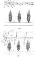
- FIG 3 is shown a greenhouse light system according to an embodiment of the invention, where several light frames 1 have been attached to the support member 4 with the aid of cable wires.
- the first cable wire 6 is attached to the base of the light frame 1 and the second cable wire 7 is attached to the side above the light frame 1.
- the cable wire 7 is in connection with the third cable wire 8, which runs in the support member 4.
- guiding rolls 9 and 10 have further been arranged in connection with the support member 4 for guiding the travel of the cable wire 7.
- the turning of the light frame 1 can be realised by guiding the cable wire 8 for example with some kind of actuator situated in the support member 4.
- the cable wires 7 attached to the light frames 1 are also pulled at the same time. This way the light frames 1 can be brought close to the support member 4, while at the same time bringing the light sources 2 close to the reflectors 3.
- FIG 4 is shown a greenhouse light system according to an embodiment of the invention, where several light frames 1 have been attached to the support member 4 with the aid of cable wires.
- the cable wire 8 is loosened, the cable wires 7 attached to the light frames 1 respectively move guided by the guiding rolls 9 and 10 and the light frames 1 turn away from the reflectors 3.
- the light frames 1 have been turned 90 degrees.
- FIG 4 is also shown an example of the transfer means of the support member 4 and the moving of the support member 4 in the vertical direction.
- the support member 4 for example a rail, is attached with the aid of cable wires 11 to some support structure 12, which stays in its place.
- the support member 4 can be lowered closer to the plants 13 by guiding the cable wires 11 for example with some device situated in the support structure 12.
- the greenhouse light can function as a so-called intermediate light.
- the intermediate light is situated between the rows of growth and makes light obtaining possible for such growth parts that are left in shadow when using light that comes from above.
- Figure 5 shows a greenhouse light according to a second embodiment of the invention.
- the electric connection device 14 of the light is encased as a separate unit.
- An advantage of the electric connection device 14 arranged outside the light frame is that the light frame 1 can be made light and thus easy to turn.
- the encased electric connection device 14 is attached to the support member 4.
- the second end of the light frame 1 has, in turn, been arranged in connection with the encased electric connection device 14 so that the light frame 1 can be turned in the directions shown by the two-ended arrow portrayed in the figure. In the situation shown in figure 5 the light has been turned 45 degrees from its first use position.
- a light source 2 which is fitted into the lamp holder 15 in the light frame 1.
- Connecting wires (not shown) have been installed in the light in order to provide the electric connection between the electric connection device 14 and the lamp holder 15.
- the inlets of the connection wires have been made waterproof.
- the light further comprises a reflector 3, which is attached to the support member 4.
Landscapes
- Engineering & Computer Science (AREA)
- General Engineering & Computer Science (AREA)
- Life Sciences & Earth Sciences (AREA)
- Environmental Sciences (AREA)
- Cultivation Of Plants (AREA)
- Securing Globes, Refractors, Reflectors Or The Like (AREA)
- Non-Portable Lighting Devices Or Systems Thereof (AREA)
Applications Claiming Priority (1)
| Application Number | Priority Date | Filing Date | Title |
|---|---|---|---|
| FI20080099A FI119951B (fi) | 2008-02-12 | 2008-02-12 | Kasvihuonevalaisin, kasvihuonevalaisinjärjestelmä ja menetelmä kasvihuonevalaisimen säteilykuvion muuttamiseksi |
Publications (3)
| Publication Number | Publication Date |
|---|---|
| EP2090824A2 true EP2090824A2 (de) | 2009-08-19 |
| EP2090824A3 EP2090824A3 (de) | 2014-10-29 |
| EP2090824B1 EP2090824B1 (de) | 2016-09-28 |
Family
ID=39148879
Family Applications (1)
| Application Number | Title | Priority Date | Filing Date |
|---|---|---|---|
| EP09152454.6A Not-in-force EP2090824B1 (de) | 2008-02-12 | 2009-02-10 | Gewächshauslicht, Gewächshauslichtsystem und Verfahren zum Ändern des Strahlenmusters eines Gewächshauslichts |
Country Status (4)
| Country | Link |
|---|---|
| EP (1) | EP2090824B1 (de) |
| EA (1) | EA017747B1 (de) |
| FI (1) | FI119951B (de) |
| UA (1) | UA93558C2 (de) |
Cited By (6)
| Publication number | Priority date | Publication date | Assignee | Title |
|---|---|---|---|---|
| WO2010089455A1 (en) * | 2009-02-04 | 2010-08-12 | Assimilight Oy Ltd | Method and arrangement for illuminating greenhouse plants |
| CN102318522A (zh) * | 2011-08-08 | 2012-01-18 | 南京农业大学 | 一种光源自动移行的温室间歇性补光系统 |
| WO2013160534A1 (en) * | 2012-04-27 | 2013-10-31 | Valoya Oy | A tilting horticultural light and method of plant cultivation |
| WO2017184448A1 (en) * | 2016-04-20 | 2017-10-26 | Bright Agrotech, Inc. | Light trolley system |
| US10598366B1 (en) | 2019-04-29 | 2020-03-24 | Mjnn, Llc | Hydroponic tower compatible light system |
| EP3358936B1 (de) * | 2015-10-06 | 2021-05-19 | OSRAM GmbH | Beleuchtungssystem und zugehöriges verfahren |
Families Citing this family (2)
| Publication number | Priority date | Publication date | Assignee | Title |
|---|---|---|---|---|
| RU178403U1 (ru) * | 2017-12-26 | 2018-04-05 | Общество с ограниченной ответственностью "Люмен" (ООО "Люмен") | Светодиодный светильник для теплиц |
| RU183572U1 (ru) * | 2018-05-21 | 2018-09-26 | федеральное государственное бюджетное образовательное учреждение высшего образования "Донской государственный технический университет" (ДГТУ) | Устройство фотобиологической светостимуляции семян плодово-ягодных, овощных и зеленных культур |
Citations (2)
| Publication number | Priority date | Publication date | Assignee | Title |
|---|---|---|---|---|
| US5095414A (en) | 1991-06-07 | 1992-03-10 | The United States Of America As Represented By The Secretary Of Agriculture | Greenhouse illumination system |
| US6312139B1 (en) | 1999-11-23 | 2001-11-06 | Pioneer Hi-Bred International, Inc. | Vertically adjustable overhead lighting system |
Family Cites Families (8)
| Publication number | Priority date | Publication date | Assignee | Title |
|---|---|---|---|---|
| AT341617B (de) * | 1973-03-12 | 1978-02-27 | Ruthner Othmar | Beleuchtungseinrichtung fur kulturanlagen, insbesondere gewachshauser |
| US3931695A (en) * | 1975-01-09 | 1976-01-13 | Controlled Environment Systems Inc. | Plant growth method and apparatus |
| US4146993A (en) * | 1976-11-17 | 1979-04-03 | Freeman Sr Leslie C | Lighting system for facilitating plant growth |
| SU1018592A1 (ru) * | 1981-04-13 | 1983-05-23 | Всесоюзный Научно-Исследовательский Биотехнический Институт | Устройство дл облучени растений в теплице |
| US5012398A (en) * | 1990-01-18 | 1991-04-30 | Musco Corp. | Light bar leveler |
| US5993030A (en) * | 1998-02-03 | 1999-11-30 | Barcel; Barton J. | Travelling lighting system |
| NL1026725C2 (nl) * | 2004-07-26 | 2006-01-30 | Hortilux Schreder B V | Werkwijze, kas alsmede een inrichting voor het belichten van gewas. |
| EP1828676A1 (de) * | 2004-10-29 | 2007-09-05 | Hortilux Schréder B.V. | Beleuchtung für gewächshaus |
-
2008
- 2008-02-12 FI FI20080099A patent/FI119951B/fi not_active IP Right Cessation
-
2009
- 2009-02-10 EP EP09152454.6A patent/EP2090824B1/de not_active Not-in-force
- 2009-02-11 UA UAA200901100A patent/UA93558C2/ru unknown
- 2009-02-11 EA EA200900179A patent/EA017747B1/ru not_active IP Right Cessation
Patent Citations (2)
| Publication number | Priority date | Publication date | Assignee | Title |
|---|---|---|---|---|
| US5095414A (en) | 1991-06-07 | 1992-03-10 | The United States Of America As Represented By The Secretary Of Agriculture | Greenhouse illumination system |
| US6312139B1 (en) | 1999-11-23 | 2001-11-06 | Pioneer Hi-Bred International, Inc. | Vertically adjustable overhead lighting system |
Cited By (8)
| Publication number | Priority date | Publication date | Assignee | Title |
|---|---|---|---|---|
| WO2010089455A1 (en) * | 2009-02-04 | 2010-08-12 | Assimilight Oy Ltd | Method and arrangement for illuminating greenhouse plants |
| CN102318522A (zh) * | 2011-08-08 | 2012-01-18 | 南京农业大学 | 一种光源自动移行的温室间歇性补光系统 |
| WO2013160534A1 (en) * | 2012-04-27 | 2013-10-31 | Valoya Oy | A tilting horticultural light and method of plant cultivation |
| EP3358936B1 (de) * | 2015-10-06 | 2021-05-19 | OSRAM GmbH | Beleuchtungssystem und zugehöriges verfahren |
| US11109539B2 (en) | 2015-10-06 | 2021-09-07 | Osram Gmbh | Lighting system and corresponding method |
| WO2017184448A1 (en) * | 2016-04-20 | 2017-10-26 | Bright Agrotech, Inc. | Light trolley system |
| US10390495B2 (en) | 2016-04-20 | 2019-08-27 | Minn, Llc | Light trolley system |
| US10598366B1 (en) | 2019-04-29 | 2020-03-24 | Mjnn, Llc | Hydroponic tower compatible light system |
Also Published As
| Publication number | Publication date |
|---|---|
| EA200900179A1 (ru) | 2009-08-28 |
| FI20080099A0 (fi) | 2008-02-12 |
| UA93558C2 (ru) | 2011-02-25 |
| EP2090824B1 (de) | 2016-09-28 |
| EA017747B1 (ru) | 2013-02-28 |
| FI119951B (fi) | 2009-05-15 |
| EP2090824A3 (de) | 2014-10-29 |
Similar Documents
| Publication | Publication Date | Title |
|---|---|---|
| EP2090824B1 (de) | Gewächshauslicht, Gewächshauslichtsystem und Verfahren zum Ändern des Strahlenmusters eines Gewächshauslichts | |
| EP1145622B1 (de) | Lichtabschirmungsvorrichtung | |
| US6312139B1 (en) | Vertically adjustable overhead lighting system | |
| FI124081B (fi) | Menelmä ja järjestely kasvihuonekasvien valaisemiseksi | |
| US7475512B2 (en) | Method, greenhouse and an installation for illuminating plants | |
| FI124137B (fi) | Menetelmä ja järjestely kasvihuonekasvien valaisemiseksi sekä kasvihuoneessa käytettävä vaunu | |
| JP2009106208A (ja) | 植物栽培の照明装置 | |
| WO2010109395A1 (en) | Device for enhancing growth of at least one plant as well as such a method | |
| US20240052997A1 (en) | Top lighting and interlighting luminaire assembly with movable light source | |
| EP3420274B1 (de) | Leuchtkörper | |
| JP4877111B2 (ja) | 植物照明装置 | |
| CN113154274B (zh) | 植物光照装置 | |
| JP6566429B2 (ja) | 植物育成用照明装置 | |
| EP1671062A1 (de) | Beleuchtungssystem mit beweglicher beleuchtung sowie eine kombination aus mindestens zwei beleuchtungssystemen mit beweglicher beleuchtung und verfahren zum getreideanbau | |
| KR101166780B1 (ko) | 온실용 조명장치 | |
| CN115380187A (zh) | 用于优化室内农场中的光分布的可调灯罩式反射器 | |
| WO2005104817A1 (en) | Device and method for illuminating plants and an insert intended for use with the device | |
| US20160069543A1 (en) | Luminaire and luminaire components | |
| CN209262762U (zh) | 一种全光谱植物生长灯 | |
| AU2015311607B2 (en) | Luminaire and luminaire components | |
| KR20200007225A (ko) | 식물 생육용 조명장치 | |
| WO2024144788A1 (en) | Plant lighting system | |
| KR20210053566A (ko) | 온실용 조명장치 |
Legal Events
| Date | Code | Title | Description |
|---|---|---|---|
| PUAI | Public reference made under article 153(3) epc to a published international application that has entered the european phase |
Free format text: ORIGINAL CODE: 0009012 |
|
| AK | Designated contracting states |
Kind code of ref document: A2 Designated state(s): AT BE BG CH CY CZ DE DK EE ES FI FR GB GR HR HU IE IS IT LI LT LU LV MC MK MT NL NO PL PT RO SE SI SK TR |
|
| AX | Request for extension of the european patent |
Extension state: AL BA RS |
|
| PUAL | Search report despatched |
Free format text: ORIGINAL CODE: 0009013 |
|
| AK | Designated contracting states |
Kind code of ref document: A3 Designated state(s): AT BE BG CH CY CZ DE DK EE ES FI FR GB GR HR HU IE IS IT LI LT LU LV MC MK MT NL NO PL PT RO SE SI SK TR |
|
| AX | Request for extension of the european patent |
Extension state: AL BA RS |
|
| RIC1 | Information provided on ipc code assigned before grant |
Ipc: F21V 19/02 20060101ALI20140924BHEP Ipc: A01G 9/26 20060101AFI20140924BHEP Ipc: F21V 14/02 20060101ALI20140924BHEP Ipc: F21V 21/15 20060101ALN20140924BHEP |
|
| 17P | Request for examination filed |
Effective date: 20150427 |
|
| RBV | Designated contracting states (corrected) |
Designated state(s): AT BE BG CH CY CZ DE DK EE ES FI FR GB GR HR HU IE IS IT LI LT LU LV MC MK MT NL NO PL PT RO SE SI SK TR |
|
| AKX | Designation fees paid |
Designated state(s): AT BE BG CH CY CZ DE DK EE ES FI FR GB GR HR HU IE IS IT LI LT LU LV MC MK MT NL NO PL PT RO SE SI SK TR |
|
| AXX | Extension fees paid |
Extension state: AL Extension state: RS Extension state: BA |
|
| REG | Reference to a national code |
Ref country code: DE Ref legal event code: R079 Ref document number: 602009041358 Country of ref document: DE Free format text: PREVIOUS MAIN CLASS: F21V0021140000 Ipc: A01G0009260000 |
|
| RIC1 | Information provided on ipc code assigned before grant |
Ipc: F21V 14/02 20060101ALI20160324BHEP Ipc: F21V 21/15 20060101ALN20160324BHEP Ipc: F21V 19/02 20060101ALI20160324BHEP Ipc: A01G 9/26 20060101AFI20160324BHEP |
|
| GRAP | Despatch of communication of intention to grant a patent |
Free format text: ORIGINAL CODE: EPIDOSNIGR1 |
|
| INTG | Intention to grant announced |
Effective date: 20160506 |
|
| GRAS | Grant fee paid |
Free format text: ORIGINAL CODE: EPIDOSNIGR3 |
|
| GRAA | (expected) grant |
Free format text: ORIGINAL CODE: 0009210 |
|
| RIN1 | Information on inventor provided before grant (corrected) |
Inventor name: HELLE, TIMO |
|
| AK | Designated contracting states |
Kind code of ref document: B1 Designated state(s): AT BE BG CH CY CZ DE DK EE ES FI FR GB GR HR HU IE IS IT LI LT LU LV MC MK MT NL NO PL PT RO SE SI SK TR |
|
| REG | Reference to a national code |
Ref country code: GB Ref legal event code: FG4D |
|
| REG | Reference to a national code |
Ref country code: CH Ref legal event code: EP |
|
| REG | Reference to a national code |
Ref country code: AT Ref legal event code: REF Ref document number: 831974 Country of ref document: AT Kind code of ref document: T Effective date: 20161015 |
|
| REG | Reference to a national code |
Ref country code: IE Ref legal event code: FG4D |
|
| REG | Reference to a national code |
Ref country code: DE Ref legal event code: R096 Ref document number: 602009041358 Country of ref document: DE |
|
| REG | Reference to a national code |
Ref country code: LT Ref legal event code: MG4D |
|
| PG25 | Lapsed in a contracting state [announced via postgrant information from national office to epo] |
Ref country code: NO Free format text: LAPSE BECAUSE OF FAILURE TO SUBMIT A TRANSLATION OF THE DESCRIPTION OR TO PAY THE FEE WITHIN THE PRESCRIBED TIME-LIMIT Effective date: 20161228 Ref country code: HR Free format text: LAPSE BECAUSE OF FAILURE TO SUBMIT A TRANSLATION OF THE DESCRIPTION OR TO PAY THE FEE WITHIN THE PRESCRIBED TIME-LIMIT Effective date: 20160928 Ref country code: FI Free format text: LAPSE BECAUSE OF FAILURE TO SUBMIT A TRANSLATION OF THE DESCRIPTION OR TO PAY THE FEE WITHIN THE PRESCRIBED TIME-LIMIT Effective date: 20160928 Ref country code: LT Free format text: LAPSE BECAUSE OF FAILURE TO SUBMIT A TRANSLATION OF THE DESCRIPTION OR TO PAY THE FEE WITHIN THE PRESCRIBED TIME-LIMIT Effective date: 20160928 |
|
| REG | Reference to a national code |
Ref country code: NL Ref legal event code: MP Effective date: 20160928 |
|
| REG | Reference to a national code |
Ref country code: AT Ref legal event code: MK05 Ref document number: 831974 Country of ref document: AT Kind code of ref document: T Effective date: 20160928 |
|
| PG25 | Lapsed in a contracting state [announced via postgrant information from national office to epo] |
Ref country code: LV Free format text: LAPSE BECAUSE OF FAILURE TO SUBMIT A TRANSLATION OF THE DESCRIPTION OR TO PAY THE FEE WITHIN THE PRESCRIBED TIME-LIMIT Effective date: 20160928 Ref country code: NL Free format text: LAPSE BECAUSE OF FAILURE TO SUBMIT A TRANSLATION OF THE DESCRIPTION OR TO PAY THE FEE WITHIN THE PRESCRIBED TIME-LIMIT Effective date: 20160928 Ref country code: SE Free format text: LAPSE BECAUSE OF FAILURE TO SUBMIT A TRANSLATION OF THE DESCRIPTION OR TO PAY THE FEE WITHIN THE PRESCRIBED TIME-LIMIT Effective date: 20160928 Ref country code: GR Free format text: LAPSE BECAUSE OF FAILURE TO SUBMIT A TRANSLATION OF THE DESCRIPTION OR TO PAY THE FEE WITHIN THE PRESCRIBED TIME-LIMIT Effective date: 20161229 |
|
| PG25 | Lapsed in a contracting state [announced via postgrant information from national office to epo] |
Ref country code: EE Free format text: LAPSE BECAUSE OF FAILURE TO SUBMIT A TRANSLATION OF THE DESCRIPTION OR TO PAY THE FEE WITHIN THE PRESCRIBED TIME-LIMIT Effective date: 20160928 Ref country code: RO Free format text: LAPSE BECAUSE OF FAILURE TO SUBMIT A TRANSLATION OF THE DESCRIPTION OR TO PAY THE FEE WITHIN THE PRESCRIBED TIME-LIMIT Effective date: 20160928 |
|
| PG25 | Lapsed in a contracting state [announced via postgrant information from national office to epo] |
Ref country code: CZ Free format text: LAPSE BECAUSE OF FAILURE TO SUBMIT A TRANSLATION OF THE DESCRIPTION OR TO PAY THE FEE WITHIN THE PRESCRIBED TIME-LIMIT Effective date: 20160928 Ref country code: IS Free format text: LAPSE BECAUSE OF FAILURE TO SUBMIT A TRANSLATION OF THE DESCRIPTION OR TO PAY THE FEE WITHIN THE PRESCRIBED TIME-LIMIT Effective date: 20170128 Ref country code: BG Free format text: LAPSE BECAUSE OF FAILURE TO SUBMIT A TRANSLATION OF THE DESCRIPTION OR TO PAY THE FEE WITHIN THE PRESCRIBED TIME-LIMIT Effective date: 20161228 Ref country code: PT Free format text: LAPSE BECAUSE OF FAILURE TO SUBMIT A TRANSLATION OF THE DESCRIPTION OR TO PAY THE FEE WITHIN THE PRESCRIBED TIME-LIMIT Effective date: 20170130 Ref country code: AT Free format text: LAPSE BECAUSE OF FAILURE TO SUBMIT A TRANSLATION OF THE DESCRIPTION OR TO PAY THE FEE WITHIN THE PRESCRIBED TIME-LIMIT Effective date: 20160928 Ref country code: ES Free format text: LAPSE BECAUSE OF FAILURE TO SUBMIT A TRANSLATION OF THE DESCRIPTION OR TO PAY THE FEE WITHIN THE PRESCRIBED TIME-LIMIT Effective date: 20160928 Ref country code: SK Free format text: LAPSE BECAUSE OF FAILURE TO SUBMIT A TRANSLATION OF THE DESCRIPTION OR TO PAY THE FEE WITHIN THE PRESCRIBED TIME-LIMIT Effective date: 20160928 Ref country code: PL Free format text: LAPSE BECAUSE OF FAILURE TO SUBMIT A TRANSLATION OF THE DESCRIPTION OR TO PAY THE FEE WITHIN THE PRESCRIBED TIME-LIMIT Effective date: 20160928 Ref country code: BE Free format text: LAPSE BECAUSE OF FAILURE TO SUBMIT A TRANSLATION OF THE DESCRIPTION OR TO PAY THE FEE WITHIN THE PRESCRIBED TIME-LIMIT Effective date: 20160928 |
|
| REG | Reference to a national code |
Ref country code: DE Ref legal event code: R097 Ref document number: 602009041358 Country of ref document: DE |
|
| PG25 | Lapsed in a contracting state [announced via postgrant information from national office to epo] |
Ref country code: IT Free format text: LAPSE BECAUSE OF FAILURE TO SUBMIT A TRANSLATION OF THE DESCRIPTION OR TO PAY THE FEE WITHIN THE PRESCRIBED TIME-LIMIT Effective date: 20160928 |
|
| PG25 | Lapsed in a contracting state [announced via postgrant information from national office to epo] |
Ref country code: DK Free format text: LAPSE BECAUSE OF FAILURE TO SUBMIT A TRANSLATION OF THE DESCRIPTION OR TO PAY THE FEE WITHIN THE PRESCRIBED TIME-LIMIT Effective date: 20160928 |
|
| PLBE | No opposition filed within time limit |
Free format text: ORIGINAL CODE: 0009261 |
|
| STAA | Information on the status of an ep patent application or granted ep patent |
Free format text: STATUS: NO OPPOSITION FILED WITHIN TIME LIMIT |
|
| REG | Reference to a national code |
Ref country code: DE Ref legal event code: R119 Ref document number: 602009041358 Country of ref document: DE |
|
| 26N | No opposition filed |
Effective date: 20170629 |
|
| PG25 | Lapsed in a contracting state [announced via postgrant information from national office to epo] |
Ref country code: MC Free format text: LAPSE BECAUSE OF FAILURE TO SUBMIT A TRANSLATION OF THE DESCRIPTION OR TO PAY THE FEE WITHIN THE PRESCRIBED TIME-LIMIT Effective date: 20160928 |
|
| REG | Reference to a national code |
Ref country code: CH Ref legal event code: PL |
|
| GBPC | Gb: european patent ceased through non-payment of renewal fee |
Effective date: 20170210 |
|
| PG25 | Lapsed in a contracting state [announced via postgrant information from national office to epo] |
Ref country code: LI Free format text: LAPSE BECAUSE OF NON-PAYMENT OF DUE FEES Effective date: 20170228 Ref country code: CH Free format text: LAPSE BECAUSE OF NON-PAYMENT OF DUE FEES Effective date: 20170228 |
|
| REG | Reference to a national code |
Ref country code: IE Ref legal event code: MM4A |
|
| PG25 | Lapsed in a contracting state [announced via postgrant information from national office to epo] |
Ref country code: SI Free format text: LAPSE BECAUSE OF FAILURE TO SUBMIT A TRANSLATION OF THE DESCRIPTION OR TO PAY THE FEE WITHIN THE PRESCRIBED TIME-LIMIT Effective date: 20160928 |
|
| REG | Reference to a national code |
Ref country code: FR Ref legal event code: ST Effective date: 20171031 |
|
| PG25 | Lapsed in a contracting state [announced via postgrant information from national office to epo] |
Ref country code: LU Free format text: LAPSE BECAUSE OF NON-PAYMENT OF DUE FEES Effective date: 20170210 |
|
| PG25 | Lapsed in a contracting state [announced via postgrant information from national office to epo] |
Ref country code: DE Free format text: LAPSE BECAUSE OF NON-PAYMENT OF DUE FEES Effective date: 20170901 Ref country code: FR Free format text: LAPSE BECAUSE OF NON-PAYMENT OF DUE FEES Effective date: 20170228 |
|
| PG25 | Lapsed in a contracting state [announced via postgrant information from national office to epo] |
Ref country code: GB Free format text: LAPSE BECAUSE OF NON-PAYMENT OF DUE FEES Effective date: 20170210 Ref country code: IE Free format text: LAPSE BECAUSE OF NON-PAYMENT OF DUE FEES Effective date: 20170210 |
|
| PG25 | Lapsed in a contracting state [announced via postgrant information from national office to epo] |
Ref country code: MT Free format text: LAPSE BECAUSE OF NON-PAYMENT OF DUE FEES Effective date: 20170210 |
|
| PG25 | Lapsed in a contracting state [announced via postgrant information from national office to epo] |
Ref country code: HU Free format text: LAPSE BECAUSE OF FAILURE TO SUBMIT A TRANSLATION OF THE DESCRIPTION OR TO PAY THE FEE WITHIN THE PRESCRIBED TIME-LIMIT; INVALID AB INITIO Effective date: 20090210 |
|
| PG25 | Lapsed in a contracting state [announced via postgrant information from national office to epo] |
Ref country code: CY Free format text: LAPSE BECAUSE OF NON-PAYMENT OF DUE FEES Effective date: 20160928 |
|
| PG25 | Lapsed in a contracting state [announced via postgrant information from national office to epo] |
Ref country code: MK Free format text: LAPSE BECAUSE OF FAILURE TO SUBMIT A TRANSLATION OF THE DESCRIPTION OR TO PAY THE FEE WITHIN THE PRESCRIBED TIME-LIMIT Effective date: 20160928 |
|
| PG25 | Lapsed in a contracting state [announced via postgrant information from national office to epo] |
Ref country code: TR Free format text: LAPSE BECAUSE OF FAILURE TO SUBMIT A TRANSLATION OF THE DESCRIPTION OR TO PAY THE FEE WITHIN THE PRESCRIBED TIME-LIMIT Effective date: 20160928 |