EP2090831A1 - Backofentür - Google Patents
Backofentür Download PDFInfo
- Publication number
- EP2090831A1 EP2090831A1 EP08002598A EP08002598A EP2090831A1 EP 2090831 A1 EP2090831 A1 EP 2090831A1 EP 08002598 A EP08002598 A EP 08002598A EP 08002598 A EP08002598 A EP 08002598A EP 2090831 A1 EP2090831 A1 EP 2090831A1
- Authority
- EP
- European Patent Office
- Prior art keywords
- door
- unit
- ventilation
- opening
- oven
- Prior art date
- Legal status (The legal status is an assumption and is not a legal conclusion. Google has not performed a legal analysis and makes no representation as to the accuracy of the status listed.)
- Granted
Links
- 238000009423 ventilation Methods 0.000 claims abstract description 45
- 238000010411 cooking Methods 0.000 claims abstract description 20
- 239000003570 air Substances 0.000 claims description 35
- 239000002184 metal Substances 0.000 claims description 7
- 239000012080 ambient air Substances 0.000 claims description 4
- 229910000831 Steel Inorganic materials 0.000 claims description 2
- 239000010959 steel Substances 0.000 claims description 2
- 238000003780 insertion Methods 0.000 description 12
- 230000037431 insertion Effects 0.000 description 12
- 238000001816 cooling Methods 0.000 description 6
- 210000003746 feather Anatomy 0.000 description 4
- 238000007664 blowing Methods 0.000 description 3
- 238000005452 bending Methods 0.000 description 2
- 238000004140 cleaning Methods 0.000 description 2
- 239000011521 glass Substances 0.000 description 2
- 238000012423 maintenance Methods 0.000 description 2
- 238000004519 manufacturing process Methods 0.000 description 2
- 230000006641 stabilisation Effects 0.000 description 2
- 239000012780 transparent material Substances 0.000 description 2
- 230000004888 barrier function Effects 0.000 description 1
- 238000010276 construction Methods 0.000 description 1
- 230000007423 decrease Effects 0.000 description 1
- 239000000463 material Substances 0.000 description 1
Images


Classifications
-
- F—MECHANICAL ENGINEERING; LIGHTING; HEATING; WEAPONS; BLASTING
- F24—HEATING; RANGES; VENTILATING
- F24C—DOMESTIC STOVES OR RANGES ; DETAILS OF DOMESTIC STOVES OR RANGES, OF GENERAL APPLICATION
- F24C15/00—Details
- F24C15/02—Doors specially adapted for stoves or ranges
- F24C15/04—Doors specially adapted for stoves or ranges with transparent panels
-
- F—MECHANICAL ENGINEERING; LIGHTING; HEATING; WEAPONS; BLASTING
- F24—HEATING; RANGES; VENTILATING
- F24C—DOMESTIC STOVES OR RANGES ; DETAILS OF DOMESTIC STOVES OR RANGES, OF GENERAL APPLICATION
- F24C15/00—Details
- F24C15/006—Arrangements for circulation of cooling air
Definitions
- the present invention relates to a door for closing a cooking cavity of an oven, especially of a household oven, with a first unit and a second unit.
- DE 84 13 224 U1 describes an oven door, with a front cover which comprises feather elements directed towards the inner door part to connect the front part with the inner part.
- the inner part is made from sheet metal in one piece. This piece contains the inner window and the door frame.
- the frame part of the inner part comprises openings in order to connect the inner part with feather elements of the front part.
- the feather elements snap into these openings for connection, and can be released for disassembling the door parts.
- sheet metal does not meet the durability requirements of a modern oven door. Also, the outer surface of the door is not cooled or isolated.
- DE 101 63 150 shows an oven door where the plates are connected through corner elements and horizontal and vertical elements. All these elements constitute a door frame in an assembled condition of the door.
- One disadvantage of this oven door is that there is no ventilation of the interior space possible. The exactly aligned horizontal and vertical elements complicate the assembling of the door. Finally, these pieces are expensive to produce.
- an oven door whose inner plate can be removed.
- the door has an upper and lower horizontal element. Between the upper horizontal element and an upper end element a pivotal point for turning the inner plate is arranged.
- the inner plate is connected with the lower horizontal element which snaps in a connection part of the feather element to fix the door plates. This enables the inner plate to be fold out, but the inner plate cannot be taken out. For this design, a lot of different parts are necessary, which are expensive and time consuming in their manufacture. Finally, for this door no ventilation is provided.
- DE 696 09 223 T2 shows an oven door with a detachable device.
- Side bars build a frame on the inner plate.
- connection elements are arranged, so that these two devices can be snapped together. Guiding elements on both devices provide the correct assembling.
- This connection is detachable.
- the main disadvantage is that the devices are connected only though single points. So this connection is not very durable. There is no possibility of inserting an additional inside plate.
- a door for closing a cooking cavity of an oven, especially a household oven, with a first unit and a second unit characterized in that one unit is guided by at least one detachable or releasable connection means, in particular snapping and/or plugging and/or sliding means, in the other unit, and at least one unit is provided with at least one opening for ventilation, which is connected in a closed position of the door to an air suction area of the oven.
- the detachable or releasable connection means facilitate production, maintenance as well as cleaning of the door.
- the first unit is an outer unit and contains a front plate, two vertical elements arranged in parallel on the front plate and at least one inside plate arranged between the vertical elements.
- a front plate two vertical elements arranged in parallel on the front plate and at least one inside plate arranged between the vertical elements.
- This enables a compact and stable structure of the front plate and the at least one inside plate which is, in addition, mountable in an easy way.
- the second unit is an inner unit and contains an inner plate and a frame, which extends over the side areas and the upper transversal area of the inner plate.
- the structure which is carrying the at least one inside plate can be covered so that dirt can be reduced. If dirt intrudes nevertheless, it can be easily removed after detaching or releasing the connection of the two units.
- the at least one opening for ventilation is arranged close to the upper transversal area of the inner plate. This makes it possible to ventilate the plates up to their upper end.
- the at least one opening for ventilation is located in the same plane or at the same level as the inner plate, that means they are directed towards the oven when the door is locked.
- the air suction area of the oven which is the area where the at least one ventilation opening normally leads to, can advantageously be arranged over the cooking cavity.
- the at least one opening for ventilation extends in a horizontal direction over about the width of the inside plates. That provides a maximum cross sectional area of the air flow, and improves the cooling of the oven door.
- two or more openings for ventilation can be arranged side by side so that the air flow can disperse over the whole cross sectional area advantageously.
- the at least one opening for ventilation is arranged between the upper transversal area of the frame and the inner plate. It is possible that this is provided through a distance or gap between these two parts.
- the at least one opening for ventilation is arranged in a separate ventilation bar, which is preferably placed between the transversal frame part and the inner plate.
- the ventilation bar preferably extends also into the inside of the door, which stabilises the complete door construction. Furthermore, the air flow can advantageously lead from the door inside to the air suction area of the oven through the ventilation bar without any turbulences.
- the at least one opening for ventilation is arranged in an extension of the frame which adjoins the inner plate at the level of the cooking cavity. In this area of the frame part, the openings for ventilation can be inserted.
- the interior area of the door has preferably at least one opening or opens towards the bottom, so that ambient air can be sucked in from the surrounding environment outside the oven.
- the ventilation of the door is provided by an air flow, which gets sucked in from the bottom, is lead through the inside of the door and directed through the at least one opening for ventilation to the air suction area of the oven.
- the air flow cross section stays at least approximately the same inside the door.
- the vertical connection elements are arranged in the side areas of the unit, so that the air flow has no barriers to bypass and can be easily guided without turbulences from the bottom of the door to the upper openings for ventilation.
- the second unit is mounted on the first unit.
- the frame is guided by at least one connection means in the vertical elements of the first unit.
- the connection of the two units is realized with at least one bayonet connection.
- one unit is put on the other at first and then the two units are slided against each other, so that shaped connection means of one unit can reach into corresponding recesses, the bayonet openings or recesses, of the other unit.
- several connection means are arranged on each side of the units which can be connected at the same time so that the two units can be connected easily one the one hand but also establish a stable connection on the other hand.
- the shaped connection means snap into a final position, which is the position when both units form the assembled door, in corresponding gaps to establish and fix the connection of the two units.
- This connection can be unfixed by opening the snapping connection and sliding one unit out of the bayonet guides. So the door can be disjoined in its main parts, the two door units, for cleaning or maintenance.
- the door frame is made at least essentially of metal.
- the door frame is made at least essentially of steel. This has the advantage that the frame can be cleaned particularly easily and the connection of the two units is very durable. It is also possible to have only parts of the frame made of metal. However, this invention is not limited to the use of metal for the frame, instead of metal any other suitable material can be taken.
- the plates are usually made of glass or other transparent material.
- the first unit comprises at least one snapping device, particularly a snapping hook
- the second unit comprises at least one opening, particularly with a rectangular shape, where the snapping device is releasably pushable into the opening to connect the first unit and the second unit.
- the invention comprises an oven with a cooking cavity and a door for closing the cooking cavity according to one of the claims 1 to 15.
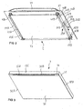
- FIG 1 and FIG 4 show a completely assembled door 1 which consists of a first unit 2 used as an outer unit and a second unit 3 used as an inner unit.
- the outer unit 2 comprises a front plate 21 of the door 1 which is visible from the outside. On the upper outer surface of the front plate 21, a handle 28 is arranged.
- the inner unit 3 is arranged on the inner surface of the front plate 21.
- the inner unit 3 comprises a frame 32, which extends over the outer side areas 32A and 32B, respectively, and the upper transversal area 32C of the inner unit 3.
- the lower transversal area 32D of the outer unit 3 no frame is provided. Consequently, the bottom of the door 1, which is not shown in FIG 1 , stays open for ventilation purposes.
- a ventilation bar 34 with openings 33A, 33B for ventilation is arranged underneath the upper transversal area 32C of the inner unit 3.
- the ventilation bar 34 has a thin stabilisation bar 35 in the middle between the openings 33A and 33B for ventilation. So the ventilation is spread over two openings for ventilation 33A and 33B.
- the plate 31 of the door 1 closes or seals the cooking cavity.
- the openings for ventilation 33A and 33B adjoin directly to an air suction area of the oven, which is placed over the cooking cavity.
- the air suction area of the oven is not shown in FIG 1 .
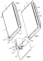
- FIG 2 shows the outer unit 2.
- the two parallel vertical elements 22A and 22B are fixed, preferably glued or screwed, on the back-sided side areas of the front plate 21. Between the vertical elements 22A and 22B, an inside plate 23 is arranged which is hold parallel to the front plate 21 by the vertical elements 22A and 22B.
- the vertical elements 22A and 22B On their outwardly directed sides, the vertical elements 22A and 22B have insertion areas 41A and 41B in the upper area, insertion areas 51A and 51B in the middle area and insertion areas 61A and 61B in the lower area.
- the insertion areas 41B, 51B and 61B Adjacent to the front plate 21, the insertion areas 41B, 51B and 61B comprise elongated supports 42B, 52B and 62B, respectively. Underneath the insertion areas 41B, 51B and 61B, also adjacent to the front plate 21, elongated openings 43B, 53B and 63B are arranged. In the lower area of the openings 43B and 53B, recesses 44B and 54B, respectively, are arranged.
- the insertion area 41B, the support 42B, the opening 43B and the recess 44B on the outward side of the vertical element 22B form a bayonet or snapping connection to fix the inner unit 3.
- the insertion area 51B, the support 52B, the opening 53B and the recess 54B on the outward side of the vertical element 22B form another bayonet or snapping connection to fix the inner unit 3.
- the insertion area 61B, the support 62B and the opening 63B on the outward side of the vertical element 22B form a third bayonet or snapping connection to fix the inner unit 3.
- the insertion area 41A, the support 42A, the opening 43A and the recess 44A on the outward side of the vertical element 22A form a bayonet or snapping connection to fix the inner unit 3.
- the insertion area 51A, the support 52A, the opening 53B and the recess 54A on the outward side of the vertical element 22A form another bayonet or snapping connection to fix the inner unit 3.
- the insertion area 61A, the support 62A, the opening 63A and the recess 64A on the outward side of the vertical element 22A form a bayonet or snapping connection to fix the inner unit 3.
- FIG 3 shows the inner unit 3.
- the frame 32 extends over the side areas 32A and 32B of the inner plate 31 of the inner unit 3 and the upper transversal area 32C over the ventilation bar 34.
- the inner plate 31 closes the cooking cavity, not shown here.
- the ventilation bar 34 adjoins to an air suction area, not shown here, which is arranged over the front of the cooking cavity.
- the connection means for connecting the inner unit 3 with the outer unit 2 which are not shown in FIG 3 are arranged on the interior side of the side areas 32A and 32B of the frame.
- connection means of the frame 32 of the inner unit 3 are positioned over the inserting areas 41A, 51A, 61A, 41B, 51B and 61B of the outer unit 2 and then concurrently inserted into these areas, orthogonally to the plane of the inner plate 31 and following direction D1.
- the units 2 and 3 are connected.
- the connecting elements of the inner unit 3 snap into a final end position into the recesses 54A, 54B of the vertical elements 22A and 22B of the outer unit 2.
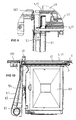
- FIG 5 shows a cross sectional view from a side view of the oven door 1.
- the ventilation bar 34 extends under the traversal area 32C of frame 32 into the interior 27 of the first unit 2 between front plate 21 and inside plate 23.
- the interior 27 of the first unit 2 is open at the bottom 9.
- ambient air flow A is sucked through the bottom 27 of the door 1 into the interior 27 of the first unit 2 to cool the front plate 21.
- the air flow A is guided between or through the space between the front plate 21 and the inside plate 23.
- the air flow A extends from the bottom to the ventilation bar at the top and finally in the air suction area of the oven.
- the cross-section of the air flow A is not noteworthy affected, as the front plate 21 and the interior plate 23 stay in their positions relative to each other. This makes it possible to optimize and preserve the form of the cross section over a long time which is helpful for maintaining the air flow A in the desired way.
- the plates 21, 23, 31 are usually made of glass or other transparent material.
- Figures 6 to 8 show another embodiment of the invention where the inner unit 3' is fixed to the outer unit 2' by two snapping hooks 72B' and, not shown, 72A'.
- the snapping hook 72B' is sprayed onto the base area of the vertical, not shown element 22B'. It comprises a support plate 71B' which works as a base plate and which comprises an edge 76B' at its outer end.
- a carrying element 75B' is arranged on the support plate 71B' where the carrying element 75B', at its outer end, forms the snapping hook 72B'.
- the snapping hook 72B' is bent downwards at a bending 74B'.
- the inner unit 3' comprises at the bottom of its side area 32B' a notch 73B'.
- the notch 73B' is formed as a rectangular opening.
- FIG 10 shows the muffle 80, the door 1 in front of the muffle and the fan 81 which is arranged above the muffle.
- an air suction channel 82 which constitutes the air suction area is arranged and above the air suction channel 82, an air blowing channel 83 is arranged.
- the fan 81 when operated, sucks the air out of the door 1 along the air suction channel 82, where it also sucks hot air out of the muffle 80 through the opening 84 above the muffle 80. After passing the fan 81, the air is blown through the blowing channel 83 and is blown out of the oven over the door 1.
- a top plate 182 is arranged.
Landscapes
- Engineering & Computer Science (AREA)
- Chemical & Material Sciences (AREA)
- Combustion & Propulsion (AREA)
- Mechanical Engineering (AREA)
- General Engineering & Computer Science (AREA)
- Electric Ovens (AREA)
Priority Applications (1)
| Application Number | Priority Date | Filing Date | Title |
|---|---|---|---|
| EP08002598.4A EP2090831B1 (de) | 2008-02-13 | 2008-02-13 | Backofentür |
Applications Claiming Priority (1)
| Application Number | Priority Date | Filing Date | Title |
|---|---|---|---|
| EP08002598.4A EP2090831B1 (de) | 2008-02-13 | 2008-02-13 | Backofentür |
Publications (2)
| Publication Number | Publication Date |
|---|---|
| EP2090831A1 true EP2090831A1 (de) | 2009-08-19 |
| EP2090831B1 EP2090831B1 (de) | 2016-07-13 |
Family
ID=39636936
Family Applications (1)
| Application Number | Title | Priority Date | Filing Date |
|---|---|---|---|
| EP08002598.4A Not-in-force EP2090831B1 (de) | 2008-02-13 | 2008-02-13 | Backofentür |
Country Status (1)
| Country | Link |
|---|---|
| EP (1) | EP2090831B1 (de) |
Cited By (4)
| Publication number | Priority date | Publication date | Assignee | Title |
|---|---|---|---|---|
| ITTO20130863A1 (it) * | 2013-10-25 | 2015-04-26 | Indesit Co Spa | Forno pirolitico con raffreddamento perfezionato |
| EP3118525A1 (de) | 2015-07-17 | 2017-01-18 | Electrolux Appliances Aktiebolag | Ofentür für einen ofeninnenraum eines backofens |
| CN108709350A (zh) * | 2018-06-08 | 2018-10-26 | 宁波欧燕电器有限公司 | 集成灶或电烤箱箱体的冷却系统 |
| CN116250738A (zh) * | 2023-03-13 | 2023-06-13 | 芜湖美的智能厨电制造有限公司 | 烤箱和烤箱灶 |
Citations (9)
| Publication number | Priority date | Publication date | Assignee | Title |
|---|---|---|---|---|
| US3889100A (en) * | 1974-07-31 | 1975-06-10 | Gen Electric | Oven ventilating system |
| GB1399874A (en) * | 1971-10-23 | 1975-07-02 | Creda Electric Ltd | Door for ovens and other heated chambers |
| DE8413224U1 (de) | 1984-04-30 | 1984-08-16 | Licentia Patent-Verwaltungs-Gmbh, 6000 Frankfurt | Tuer fuer den back- und bratraum eines bratofens |
| US5387258A (en) * | 1991-12-30 | 1995-02-07 | Fulgor S.P.A. | Self-cleaning oven |
| EP0735324A1 (de) * | 1995-03-24 | 1996-10-02 | Seb S.A. | Vereinfachte Ofentür mit abnehmbaren Modul |
| EP0900985A1 (de) * | 1997-09-04 | 1999-03-10 | AEG Hausgeräte GmbH | Verfahren zum Kühlen einer Garofentür und Garofen mit Kühleinrichtung |
| DE19906747A1 (de) | 1999-02-17 | 2000-08-24 | Imp Werke Gmbh & Co | Backofen |
| DE10163150A1 (de) | 2000-12-22 | 2002-07-11 | Miele & Cie | Gerätetür, vorzugsweise für einen Backofen |
| US20050076900A1 (en) | 2003-02-19 | 2005-04-14 | Electrolux Home Products Corporation N.V. | Cooking oven with a cooled door that permits pyrolysis |
Family Cites Families (4)
| Publication number | Priority date | Publication date | Assignee | Title |
|---|---|---|---|---|
| IT1187285B (it) * | 1985-07-15 | 1987-12-23 | Zanussi Elettrodomestici | Porta per forno,in particolare di tipo ventilato |
| DE19523772A1 (de) * | 1995-06-29 | 1997-01-02 | Bosch Siemens Hausgeraete | Hausgeräte-Tür, vorzugsweise Ofentür eines Backofens |
| US6561180B1 (en) * | 2002-01-15 | 2003-05-13 | Maytag Corporation | Oven door assembly |
| US7478502B2 (en) * | 2003-08-14 | 2009-01-20 | Gemtron Corporation | Appliance doors |
-
2008
- 2008-02-13 EP EP08002598.4A patent/EP2090831B1/de not_active Not-in-force
Patent Citations (10)
| Publication number | Priority date | Publication date | Assignee | Title |
|---|---|---|---|---|
| GB1399874A (en) * | 1971-10-23 | 1975-07-02 | Creda Electric Ltd | Door for ovens and other heated chambers |
| US3889100A (en) * | 1974-07-31 | 1975-06-10 | Gen Electric | Oven ventilating system |
| DE8413224U1 (de) | 1984-04-30 | 1984-08-16 | Licentia Patent-Verwaltungs-Gmbh, 6000 Frankfurt | Tuer fuer den back- und bratraum eines bratofens |
| US5387258A (en) * | 1991-12-30 | 1995-02-07 | Fulgor S.P.A. | Self-cleaning oven |
| EP0735324A1 (de) * | 1995-03-24 | 1996-10-02 | Seb S.A. | Vereinfachte Ofentür mit abnehmbaren Modul |
| DE69609223T2 (de) | 1995-03-24 | 2001-03-08 | Seb Sa | Vereinfachte Ofentür mit abnehmbaren Modul |
| EP0900985A1 (de) * | 1997-09-04 | 1999-03-10 | AEG Hausgeräte GmbH | Verfahren zum Kühlen einer Garofentür und Garofen mit Kühleinrichtung |
| DE19906747A1 (de) | 1999-02-17 | 2000-08-24 | Imp Werke Gmbh & Co | Backofen |
| DE10163150A1 (de) | 2000-12-22 | 2002-07-11 | Miele & Cie | Gerätetür, vorzugsweise für einen Backofen |
| US20050076900A1 (en) | 2003-02-19 | 2005-04-14 | Electrolux Home Products Corporation N.V. | Cooking oven with a cooled door that permits pyrolysis |
Cited By (9)
| Publication number | Priority date | Publication date | Assignee | Title |
|---|---|---|---|---|
| ITTO20130863A1 (it) * | 2013-10-25 | 2015-04-26 | Indesit Co Spa | Forno pirolitico con raffreddamento perfezionato |
| WO2015059659A1 (en) * | 2013-10-25 | 2015-04-30 | Indesit Company S.P.A. | Pyrolytic oven with improved cooling |
| CN105659030A (zh) * | 2013-10-25 | 2016-06-08 | 意黛喜公司 | 具有改进的冷却性能的热解炉 |
| EP3118525A1 (de) | 2015-07-17 | 2017-01-18 | Electrolux Appliances Aktiebolag | Ofentür für einen ofeninnenraum eines backofens |
| WO2017012830A1 (en) * | 2015-07-17 | 2017-01-26 | Electrolux Appliances Aktiebolag | Oven door for an oven cavity of a cooking oven |
| US20180187900A1 (en) * | 2015-07-17 | 2018-07-05 | Electrolux Appliances Aktiebolag | Oven door for an oven cavity of a cooking oven |
| AU2016296049B2 (en) * | 2015-07-17 | 2021-07-22 | Electrolux Appliances Aktiebolag | Oven door for an oven cavity of a cooking oven |
| CN108709350A (zh) * | 2018-06-08 | 2018-10-26 | 宁波欧燕电器有限公司 | 集成灶或电烤箱箱体的冷却系统 |
| CN116250738A (zh) * | 2023-03-13 | 2023-06-13 | 芜湖美的智能厨电制造有限公司 | 烤箱和烤箱灶 |
Also Published As
| Publication number | Publication date |
|---|---|
| EP2090831B1 (de) | 2016-07-13 |
Similar Documents
| Publication | Publication Date | Title |
|---|---|---|
| CN102893092B (zh) | 一种用于家庭用具的门 | |
| CN102472505B (zh) | 用于排烟罩的内部框架和排烟罩 | |
| EP2090831A1 (de) | Backofentür | |
| JP5100440B2 (ja) | 加熱調理器 | |
| EP2314931B1 (de) | Tragestruktur für ein Haushaltsgerät | |
| JP2007163127A5 (de) | ||
| EP3118525B1 (de) | Ofentür für einen ofeninnenraum eines backofens | |
| CN101356409B (zh) | 烹调器具门和具有这种烹调器具门的烹调器具 | |
| EP0549933A1 (de) | Backofentür | |
| JP5290724B2 (ja) | カーテンウォール | |
| EP2927606B1 (de) | Verbesserte dunstabzugshaube | |
| ES2342206T3 (es) | Montaje de una puerta de horno de coccion con un medio de bloqueo. | |
| EP2627951B1 (de) | Verbesserter kochherd, im besonderen für den haushalt | |
| WO2010078894A2 (en) | Household appliance, in particular oven | |
| JP4346532B2 (ja) | 誘導加熱調理器 | |
| JP3497117B2 (ja) | 電気オーブン | |
| JP2012161345A (ja) | オープンショーケース用扉装置及びそれを備えたショーケース | |
| KR101259806B1 (ko) | 공기조화기의 실내기 | |
| ES2556651T3 (es) | Horno de cocción | |
| US20220325899A1 (en) | Cooking grate for a gas burner cooktop | |
| EP4034815B1 (de) | Backofen mit türkühlungsanordnung | |
| SI22687A (sl) | Pečica s sistemom hlajenja pečniških vrat | |
| EP2505924A1 (de) | Herd mit einem Vorderrahmen und einer Herdtür, die an dem Vorderrahmen schwenkbar montiert ist | |
| GB2563305B (en) | Dual cooking appliance and method for cooling a dual cooking appliance | |
| ES1059103U (es) | Rejilla de proteccion para campana extractora de humos. |
Legal Events
| Date | Code | Title | Description |
|---|---|---|---|
| PUAI | Public reference made under article 153(3) epc to a published international application that has entered the european phase |
Free format text: ORIGINAL CODE: 0009012 |
|
| AK | Designated contracting states |
Kind code of ref document: A1 Designated state(s): AT BE BG CH CY CZ DE DK EE ES FI FR GB GR HR HU IE IS IT LI LT LU LV MC MT NL NO PL PT RO SE SI SK TR |
|
| AX | Request for extension of the european patent |
Extension state: AL BA MK RS |
|
| 17P | Request for examination filed |
Effective date: 20091118 |
|
| 17Q | First examination report despatched |
Effective date: 20091216 |
|
| AKX | Designation fees paid |
Designated state(s): AT BE BG CH CY CZ DE DK EE ES FI FR GB GR HR HU IE IS IT LI LT LU LV MC MT NL NO PL PT RO SE SI SK TR |
|
| RAP1 | Party data changed (applicant data changed or rights of an application transferred) |
Owner name: ELECTROLUX HOME PRODUCTS CORPORATION N.V. Owner name: AEG HAUSGERAETE GMBH |
|
| RAP1 | Party data changed (applicant data changed or rights of an application transferred) |
Owner name: ELECTROLUX HOME PRODUCTS CORPORATION N.V. Owner name: AEG HAUSGERAETE GMBH |
|
| RAP1 | Party data changed (applicant data changed or rights of an application transferred) |
Owner name: ELECTROLUX HOME PRODUCTS CORPORATION N.V. |
|
| GRAP | Despatch of communication of intention to grant a patent |
Free format text: ORIGINAL CODE: EPIDOSNIGR1 |
|
| INTG | Intention to grant announced |
Effective date: 20160127 |
|
| GRAS | Grant fee paid |
Free format text: ORIGINAL CODE: EPIDOSNIGR3 |
|
| GRAA | (expected) grant |
Free format text: ORIGINAL CODE: 0009210 |
|
| AK | Designated contracting states |
Kind code of ref document: B1 Designated state(s): AT BE BG CH CY CZ DE DK EE ES FI FR GB GR HR HU IE IS IT LI LT LU LV MC MT NL NO PL PT RO SE SI SK TR |
|
| REG | Reference to a national code |
Ref country code: GB Ref legal event code: FG4D |
|
| REG | Reference to a national code |
Ref country code: AT Ref legal event code: REF Ref document number: 812660 Country of ref document: AT Kind code of ref document: T Effective date: 20160715 Ref country code: CH Ref legal event code: EP |
|
| REG | Reference to a national code |
Ref country code: IE Ref legal event code: FG4D |
|
| REG | Reference to a national code |
Ref country code: DE Ref legal event code: R096 Ref document number: 602008045051 Country of ref document: DE |
|
| REG | Reference to a national code |
Ref country code: LT Ref legal event code: MG4D |
|
| REG | Reference to a national code |
Ref country code: NL Ref legal event code: MP Effective date: 20160713 |
|
| REG | Reference to a national code |
Ref country code: AT Ref legal event code: MK05 Ref document number: 812660 Country of ref document: AT Kind code of ref document: T Effective date: 20160713 |
|
| PG25 | Lapsed in a contracting state [announced via postgrant information from national office to epo] |
Ref country code: IS Free format text: LAPSE BECAUSE OF FAILURE TO SUBMIT A TRANSLATION OF THE DESCRIPTION OR TO PAY THE FEE WITHIN THE PRESCRIBED TIME-LIMIT Effective date: 20161113 Ref country code: NL Free format text: LAPSE BECAUSE OF FAILURE TO SUBMIT A TRANSLATION OF THE DESCRIPTION OR TO PAY THE FEE WITHIN THE PRESCRIBED TIME-LIMIT Effective date: 20160713 Ref country code: NO Free format text: LAPSE BECAUSE OF FAILURE TO SUBMIT A TRANSLATION OF THE DESCRIPTION OR TO PAY THE FEE WITHIN THE PRESCRIBED TIME-LIMIT Effective date: 20161013 Ref country code: FI Free format text: LAPSE BECAUSE OF FAILURE TO SUBMIT A TRANSLATION OF THE DESCRIPTION OR TO PAY THE FEE WITHIN THE PRESCRIBED TIME-LIMIT Effective date: 20160713 Ref country code: HR Free format text: LAPSE BECAUSE OF FAILURE TO SUBMIT A TRANSLATION OF THE DESCRIPTION OR TO PAY THE FEE WITHIN THE PRESCRIBED TIME-LIMIT Effective date: 20160713 Ref country code: LT Free format text: LAPSE BECAUSE OF FAILURE TO SUBMIT A TRANSLATION OF THE DESCRIPTION OR TO PAY THE FEE WITHIN THE PRESCRIBED TIME-LIMIT Effective date: 20160713 |
|
| REG | Reference to a national code |
Ref country code: FR Ref legal event code: PLFP Year of fee payment: 10 |
|
| PG25 | Lapsed in a contracting state [announced via postgrant information from national office to epo] |
Ref country code: BE Free format text: LAPSE BECAUSE OF FAILURE TO SUBMIT A TRANSLATION OF THE DESCRIPTION OR TO PAY THE FEE WITHIN THE PRESCRIBED TIME-LIMIT Effective date: 20160713 Ref country code: AT Free format text: LAPSE BECAUSE OF FAILURE TO SUBMIT A TRANSLATION OF THE DESCRIPTION OR TO PAY THE FEE WITHIN THE PRESCRIBED TIME-LIMIT Effective date: 20160713 Ref country code: GR Free format text: LAPSE BECAUSE OF FAILURE TO SUBMIT A TRANSLATION OF THE DESCRIPTION OR TO PAY THE FEE WITHIN THE PRESCRIBED TIME-LIMIT Effective date: 20161014 Ref country code: PT Free format text: LAPSE BECAUSE OF FAILURE TO SUBMIT A TRANSLATION OF THE DESCRIPTION OR TO PAY THE FEE WITHIN THE PRESCRIBED TIME-LIMIT Effective date: 20161114 Ref country code: SE Free format text: LAPSE BECAUSE OF FAILURE TO SUBMIT A TRANSLATION OF THE DESCRIPTION OR TO PAY THE FEE WITHIN THE PRESCRIBED TIME-LIMIT Effective date: 20160713 Ref country code: PL Free format text: LAPSE BECAUSE OF FAILURE TO SUBMIT A TRANSLATION OF THE DESCRIPTION OR TO PAY THE FEE WITHIN THE PRESCRIBED TIME-LIMIT Effective date: 20160713 Ref country code: ES Free format text: LAPSE BECAUSE OF FAILURE TO SUBMIT A TRANSLATION OF THE DESCRIPTION OR TO PAY THE FEE WITHIN THE PRESCRIBED TIME-LIMIT Effective date: 20160713 Ref country code: LV Free format text: LAPSE BECAUSE OF FAILURE TO SUBMIT A TRANSLATION OF THE DESCRIPTION OR TO PAY THE FEE WITHIN THE PRESCRIBED TIME-LIMIT Effective date: 20160713 |
|
| REG | Reference to a national code |
Ref country code: DE Ref legal event code: R097 Ref document number: 602008045051 Country of ref document: DE |
|
| PG25 | Lapsed in a contracting state [announced via postgrant information from national office to epo] |
Ref country code: RO Free format text: LAPSE BECAUSE OF FAILURE TO SUBMIT A TRANSLATION OF THE DESCRIPTION OR TO PAY THE FEE WITHIN THE PRESCRIBED TIME-LIMIT Effective date: 20160713 Ref country code: EE Free format text: LAPSE BECAUSE OF FAILURE TO SUBMIT A TRANSLATION OF THE DESCRIPTION OR TO PAY THE FEE WITHIN THE PRESCRIBED TIME-LIMIT Effective date: 20160713 |
|
| PLBE | No opposition filed within time limit |
Free format text: ORIGINAL CODE: 0009261 |
|
| STAA | Information on the status of an ep patent application or granted ep patent |
Free format text: STATUS: NO OPPOSITION FILED WITHIN TIME LIMIT |
|
| PG25 | Lapsed in a contracting state [announced via postgrant information from national office to epo] |
Ref country code: CZ Free format text: LAPSE BECAUSE OF FAILURE TO SUBMIT A TRANSLATION OF THE DESCRIPTION OR TO PAY THE FEE WITHIN THE PRESCRIBED TIME-LIMIT Effective date: 20160713 Ref country code: SK Free format text: LAPSE BECAUSE OF FAILURE TO SUBMIT A TRANSLATION OF THE DESCRIPTION OR TO PAY THE FEE WITHIN THE PRESCRIBED TIME-LIMIT Effective date: 20160713 Ref country code: DK Free format text: LAPSE BECAUSE OF FAILURE TO SUBMIT A TRANSLATION OF THE DESCRIPTION OR TO PAY THE FEE WITHIN THE PRESCRIBED TIME-LIMIT Effective date: 20160713 Ref country code: BG Free format text: LAPSE BECAUSE OF FAILURE TO SUBMIT A TRANSLATION OF THE DESCRIPTION OR TO PAY THE FEE WITHIN THE PRESCRIBED TIME-LIMIT Effective date: 20161013 |
|
| 26N | No opposition filed |
Effective date: 20170418 |
|
| PG25 | Lapsed in a contracting state [announced via postgrant information from national office to epo] |
Ref country code: SI Free format text: LAPSE BECAUSE OF FAILURE TO SUBMIT A TRANSLATION OF THE DESCRIPTION OR TO PAY THE FEE WITHIN THE PRESCRIBED TIME-LIMIT Effective date: 20160713 |
|
| PG25 | Lapsed in a contracting state [announced via postgrant information from national office to epo] |
Ref country code: MC Free format text: LAPSE BECAUSE OF FAILURE TO SUBMIT A TRANSLATION OF THE DESCRIPTION OR TO PAY THE FEE WITHIN THE PRESCRIBED TIME-LIMIT Effective date: 20160713 |
|
| REG | Reference to a national code |
Ref country code: CH Ref legal event code: PL |
|
| PG25 | Lapsed in a contracting state [announced via postgrant information from national office to epo] |
Ref country code: LI Free format text: LAPSE BECAUSE OF NON-PAYMENT OF DUE FEES Effective date: 20170228 Ref country code: CH Free format text: LAPSE BECAUSE OF NON-PAYMENT OF DUE FEES Effective date: 20170228 |
|
| REG | Reference to a national code |
Ref country code: IE Ref legal event code: MM4A |
|
| PG25 | Lapsed in a contracting state [announced via postgrant information from national office to epo] |
Ref country code: LU Free format text: LAPSE BECAUSE OF NON-PAYMENT OF DUE FEES Effective date: 20170213 |
|
| REG | Reference to a national code |
Ref country code: FR Ref legal event code: PLFP Year of fee payment: 11 |
|
| PG25 | Lapsed in a contracting state [announced via postgrant information from national office to epo] |
Ref country code: IE Free format text: LAPSE BECAUSE OF NON-PAYMENT OF DUE FEES Effective date: 20170213 |
|
| PG25 | Lapsed in a contracting state [announced via postgrant information from national office to epo] |
Ref country code: MT Free format text: LAPSE BECAUSE OF NON-PAYMENT OF DUE FEES Effective date: 20170213 |
|
| PGFP | Annual fee paid to national office [announced via postgrant information from national office to epo] |
Ref country code: NL Payment date: 20190126 Year of fee payment: 8 Ref country code: IT Payment date: 20190225 Year of fee payment: 12 |
|
| PGFP | Annual fee paid to national office [announced via postgrant information from national office to epo] |
Ref country code: FR Payment date: 20190220 Year of fee payment: 12 |
|
| PG25 | Lapsed in a contracting state [announced via postgrant information from national office to epo] |
Ref country code: HU Free format text: LAPSE BECAUSE OF FAILURE TO SUBMIT A TRANSLATION OF THE DESCRIPTION OR TO PAY THE FEE WITHIN THE PRESCRIBED TIME-LIMIT; INVALID AB INITIO Effective date: 20080213 |
|
| PG25 | Lapsed in a contracting state [announced via postgrant information from national office to epo] |
Ref country code: CY Free format text: LAPSE BECAUSE OF NON-PAYMENT OF DUE FEES Effective date: 20160713 |
|
| PG25 | Lapsed in a contracting state [announced via postgrant information from national office to epo] |
Ref country code: TR Free format text: LAPSE BECAUSE OF FAILURE TO SUBMIT A TRANSLATION OF THE DESCRIPTION OR TO PAY THE FEE WITHIN THE PRESCRIBED TIME-LIMIT Effective date: 20160713 |
|
| PGFP | Annual fee paid to national office [announced via postgrant information from national office to epo] |
Ref country code: DE Payment date: 20200219 Year of fee payment: 13 |
|
| GBPC | Gb: european patent ceased through non-payment of renewal fee |
Effective date: 20200213 |
|
| PG25 | Lapsed in a contracting state [announced via postgrant information from national office to epo] |
Ref country code: FR Free format text: LAPSE BECAUSE OF NON-PAYMENT OF DUE FEES Effective date: 20200229 Ref country code: GB Free format text: LAPSE BECAUSE OF NON-PAYMENT OF DUE FEES Effective date: 20200213 |
|
| REG | Reference to a national code |
Ref country code: DE Ref legal event code: R119 Ref document number: 602008045051 Country of ref document: DE |
|
| PG25 | Lapsed in a contracting state [announced via postgrant information from national office to epo] |
Ref country code: IT Free format text: LAPSE BECAUSE OF NON-PAYMENT OF DUE FEES Effective date: 20200213 |
|
| PG25 | Lapsed in a contracting state [announced via postgrant information from national office to epo] |
Ref country code: DE Free format text: LAPSE BECAUSE OF NON-PAYMENT OF DUE FEES Effective date: 20210901 |