EP2090833B1 - Ein Ofen mit einer Backofenkammer und einem Ofentürsystem - Google Patents
Ein Ofen mit einer Backofenkammer und einem Ofentürsystem Download PDFInfo
- Publication number
- EP2090833B1 EP2090833B1 EP20080002842 EP08002842A EP2090833B1 EP 2090833 B1 EP2090833 B1 EP 2090833B1 EP 20080002842 EP20080002842 EP 20080002842 EP 08002842 A EP08002842 A EP 08002842A EP 2090833 B1 EP2090833 B1 EP 2090833B1
- Authority
- EP
- European Patent Office
- Prior art keywords
- oven
- horizontal transport
- vertical door
- pivoting
- door portion
- Prior art date
- Legal status (The legal status is an assumption and is not a legal conclusion. Google has not performed a legal analysis and makes no representation as to the accuracy of the status listed.)
- Not-in-force
Links
- 238000010411 cooking Methods 0.000 title claims description 21
- 229910001369 Brass Inorganic materials 0.000 claims description 7
- 239000010951 brass Substances 0.000 claims description 7
- 239000002184 metal Substances 0.000 claims description 7
- 229910001220 stainless steel Inorganic materials 0.000 claims description 7
- 239000010935 stainless steel Substances 0.000 claims description 7
- 229920003023 plastic Polymers 0.000 claims description 4
- 238000004026 adhesive bonding Methods 0.000 claims description 3
- 239000004033 plastic Substances 0.000 claims description 3
- 238000003466 welding Methods 0.000 claims description 3
- 239000000969 carrier Substances 0.000 description 5
- 238000010276 construction Methods 0.000 description 5
- 241000287828 Gallus gallus Species 0.000 description 4
- XEEYBQQBJWHFJM-UHFFFAOYSA-N Iron Chemical compound [Fe] XEEYBQQBJWHFJM-UHFFFAOYSA-N 0.000 description 2
- 238000012986 modification Methods 0.000 description 2
- 230000004048 modification Effects 0.000 description 2
- 239000011521 glass Substances 0.000 description 1
- 239000000463 material Substances 0.000 description 1
- 238000000034 method Methods 0.000 description 1
Images


Classifications
-
- F—MECHANICAL ENGINEERING; LIGHTING; HEATING; WEAPONS; BLASTING
- F24—HEATING; RANGES; VENTILATING
- F24C—DOMESTIC STOVES OR RANGES ; DETAILS OF DOMESTIC STOVES OR RANGES, OF GENERAL APPLICATION
- F24C15/00—Details
- F24C15/02—Doors specially adapted for stoves or ranges
Definitions
- the present invention relates to an oven with a cooking oven chamber and an oven door system according to the preamble of claim 1.
- EP 0 794 389 B1 discloses an oven with a baking chamber, which is closable by an oven door.
- the oven door is guided in the manner of a drawer by at least one pull-out.
- At the inner side of a vertically extending door panel there are fastened holding elements for suspending cooking stock carriers.
- the oven door or the door panel is withdrawable in a horizontal direction from a closed setting into a stop setting.
- the pull-out carries a pivot device.
- the door panel is pivotable with respect to a vertical axis.
- This oven allows for the user an easy access to the food stuff.
- the above oven with the pivotable door panel is very complex.
- an oven with a cooking oven chamber and an oven door system is provided, therein:
- a main idea of the invention is that the (virtual or geometric) pivoting or swivel axis penetrates or runs through the vertical door portion, so that only the vertical door element or portion without any further parts is pivoting above or with respect to the horizontal transport portion which reduces the moment of inertia compared to the prior art where a vertical door rotates about an axis spaced apart from the door.
- the vertical pivoting axis extends within the vertical door portion and can, therefore, be and preferably is an eigen axis or main axis of inertia so that unbalances in rotation are reduced or eliminated compared to the prior art.
- pivoting axis passes through or penetrates the front part of the horizontal transport portion and that a pivoting bearing for the pivoting movement of the vertical door portion with respect to the horizontal transport portion is arranged in or at a front part of the horizontal transport portion. This results in a maximum degree of rotational freedom for the door portion and an increased accessibility of cooking good carriers or the cooking chamber.
- At least one holding or supporting device for at least one food stuff rack or cooking good carrier such as baking trays, grilling grids etc. is arranged at the vertical door portion, so that these racks or carriers are extracted or transported together with the door and are easily accessible in the opened position of the horizontal transport portion and thus the vertical door portion.
- the vertical door portion is pivoting only in the opened position. This guarantees stable state of the oven door between the opened position and closed position.
- the horizontal transport portion is locked or fixed with respect to the oven chassis in the opened position. This prevents that the vertical door portion of the oven door can be rotated or pivoted in the opened position and will not move at the same time in the transport direction.
- the vertical door portion of the oven door is either pivoting or translationally moveable or displaceable alternatively.
- the vertical door portion may comprise a U-shaped frame.
- the U-shaped frame is made of metal, preferably of stainless steel or brass.
- an upper side of the U-shaped frame is open or blades of the U-shape extend upwardly.
- the vertical door portion may comprise a door panel arranged at or within the U-shaped frame, wherein the blades may be inserted into the door panel.
- the door panel may be made of a low weight material, for example of plastics.
- a pintle or pivot and a bearing block may constitute the pivoting bearing.
- the pintle or pivot is preferably arranged at the bottom side of the vertical door portion or of the U-shaped frame.
- the pintle or pivot is a simple and stable construction element for the pivoting vertical door portion.
- the pintle is made of metal, preferably of stainless steel or brass.
- the pintle is connected to the U-shaped frame by welding, bolts or gluing. This contributes also to a stable construction.
- the bearing block is arranged on or within the horizontal transport portion, in particular in the front part of the horizontal transport portion.
- the pintle and the bearing block may form a rotary union or pivoting connection between the vertical door portion and the horizontal transport portion. This reduces the complexity of the whole construction.
- the pintle is arranged in the centre of the bottom side of the U-shaped frame.
- the bearing block is arranged in the centre of the front end part of the horizontal transport portion. This symmetric construction reduces the load for the pintle, the bearing block and other elements.
- At least one holding or supporting device for holding cooking good carriers or food stuff racks is arranged at the vertical door portion, in general at an inner side of the vertical door portion.
- Holding devices may be arranged horizontally spaced apart for the same cooking good carrier and further holding devices also vertically spaced apart for different cooking good carriers at different levels.
- holding devices may be arranged at both or opposite sides. This allows the cooking of some food stuff on the inner side and the preparing of other food stuff on the outer side at the same time. In particular, this is advantageous for ovens with professional applications.
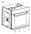
- FIG. 1 illustrates a perspective view of an oven according to a preferred embodiment of the invention.
- the oven includes a chassis 10 with a cooking oven chamber 12 inside said chassis 10. Further, the oven includes an oven door 14 comprising a vertical door portion 16 and a horizontal transport portion 18.
- the horizontal transport portion 18 of the oven door 14 is moveable in a horizontal translation or transport direction T between an opened position and a closed position.
- FIG. 1 shows the closed position. In said closed position the horizontal transport portion 18 is arranged within the chassis 10 of the oven. In said closed position the vertical door portion 16 of the oven door system 14 covers an opening of the cooking oven chamber 12.
- FIG. 2 illustrates a perspective view of the oven according to the preferred embodiment of the invention in the opened position.
- the bigger part of the horizontal transport portion 18 is out of the chassis 10.
- the vertical portion 16 is supported by the horizontal transport portion 18.
- the oven door system 14 is moveable in the chassis 10 like a drawer.
- the chassis 10 includes a cavity arranged under the cooking oven chamber 12.
- the horizontal transport portion 18 is moveable into said cavity. In the closed position the horizontal transport portion 18 is substantially inside the cavity as shown in FIG. 1 .
- the vertical portion 16 is arranged pivoting around a vertical swivel axis 20 on the horizontal transport portion 18. In FIG. 1 and FIG. 2 the vertical door portion 16 is in a basic position in relation to the horizontal transport portion 18.
- FIG. 3 illustrates a perspective view of the oven according to the preferred embodiment of the invention in the opened position of the horizontal transport portion 18. Additionally, the vertical door portion 16 is in a pivoted position. In FIG. 3 the vertical door portion 16 is pivoted about 100° from the basic position shown in FIG. 2 . The vertical door portion 16 is pivoting an arbitrary angle about the swivel axis 20. Preferably, the vertical door portion 16 is pivotable between 90° and 180° from the basic position.
- the vertical door portion 16 On its inner side 22 the vertical door portion 16 comprises a holding device 24.
- the holding device 24 is provided to attach food stuff racks like baking sheets, baking trays, broiler and/or broilers. This allows an easy access to the baking sheets, baking trays, broiler and/or broilers, respectively, for the user.
- FIG. 4 illustrates a further perspective view of the oven according to the preferred embodiment of the present invention.
- the vertical door portion 16 and the horizontal transport portion 18 are in the same position as in FIG. 3 .
- the oven is shown from an opposite side.
- FIG. 5 illustrates a perspective view of the horizontal transport portion 18 and a U-shaped frame 26 according to the preferred embodiment of the present invention.
- the U-shaped frame 26 is a part of the vertical door portion 16.
- the U-shaped frame 26 is made of metal, preferably stainless steel or brass.
- FIG. 6 illustrates a perspective view of the horizontal transport portion 18 and the U-shaped frame 26 in a turned state according to the preferred embodiment of the invention.
- FIG. 5 demonstrates how the U-shaped frame 26 is pivoting around the vertical axis 20.
- a bearing block In a front end part 28 of the horizontal transport portion 18 there is a bearing block.
- the bearing block is arranged in the centre of said front end part 28.
- the bearing block is made of metal, preferably brass or stain-less steel.
- a pintle which is not shown in FIG. 6 .
- Said pintle extends down from the bottom side of the U-shaped frame 26.
- the pintle is connected to the U-shaped frame 26 by welding, bolts or gluing.
- the pintle may be also be made of metal, preferably brass or stain-less steel.
- the pintle is inserted in the bearing block.
- the pintle and the bearing block may be secured by at least one screw.
- the pintle and the bearing block form a rotary union between the vertical door portion 16 and the horizontal transport portion 18.
- the U-shaped frame 26 is provided to hold a door panel.
- the door panel is inserted between the blades of the U-shaped frame 26.
- the door panel is made of plastics.
- a window in the door panel is made of glass or transparent plastics.
- the door panel is arranged at the blades of the U-shaped frame 26.
- the blades of the U-shaped frame 26 may be inserted into the door panel. After that the U-shaped frame 26 and the door panel may be screwed together.
- the U-shaped frame 26 may include holes for carrying balls or embossments in the front end part 28 of the horizontal transport portion 18. This guarantees the parallel position of the vertical door portion 16 in relation to the front end part 28 of the horizontal transport portion 18 after the vertical door portion 16 has been pivoted.
- Holes 27 in the frame 26 and 37 in the front part 28 may be provided, for instance to allow for air stream or condensate disposal, which holes 27 and 37 will overlap or be arranged on top of each other in the not pivoted position of the door portion 18 and frame 26 as shown in FIG. 5 .
Landscapes
- Engineering & Computer Science (AREA)
- Chemical & Material Sciences (AREA)
- Combustion & Propulsion (AREA)
- Mechanical Engineering (AREA)
- General Engineering & Computer Science (AREA)
- Electric Stoves And Ranges (AREA)
- Baking, Grill, Roasting (AREA)
Claims (6)
- Ofen mit einem Garraum (12) und einem Ofentürsystem (14), wobei:- das Ofentürsystem (14) einen vertikalen Türabschnitt (16) und einen horizontalen Transportabschnitt (18) umfasst,- der horizontale Transportabschnitt (18) vorgesehen ist, um den vertikalen Türabschnitt (16) zu halten und zu transportieren,- der horizontale Transportabschnitt (18) in einer horizontalen Richtung zwischen einer geschlossenen Stellung und einer geöffneten Stellung beweglich ist,- der vertikale Türabschnitt (16) vorgesehen ist, um in der geschlossenen Stellung eine öffnung des Garraums (12) zu bedecken oder zu verschließen,- der vertikale Türabschnitt (16) in Bezug auf den horizontalen Transportabschnitt (18) um eine vertikale Schwenkachse (20) schwenkbar oder schwenkend angeordnet ist,- ein Schwenklager für die Schwenkbewegung des vertikalen Türabschnitts (16) in Bezug auf den horizontalen Transportabschnitt (18) vorgesehen ist,dadurch gekennzeichnet, dass- die Schwenkachse (20) durch den vertikalen Türabschnitt (16) und einen Frontteil (28) des horizontalen Transportabschnitts (18) verläuft und dass das Schwenklager für die Schwenkbewegung des vertikalen Türabschnitts (16) in Bezug auf den horizontalen Transportabschnitt (18) in oder an dem Frontteil (28) des horizontalen Transportabschnitts (18) angeordnet ist.
- Ofen nach Anspruch 1, wobei der vertikale Türabschnitt (16) nur in der geöffneten Stellung schwenkbar ist oder schwenkt und/oder wobei der horizontale Transportabschnitt (18) in der geöffneten Stellung in Bezug auf den Rahmen (10) verriegelt ist.
- Ofen nach Anspruch 1 oder Anspruch 2, wobei der vertikale Türabschnitt (16) oder das Schwenklager einen U-förmigen Rahmen (26) umfasst, der vorzugsweise an einer oberen Seite offen ist und/oder der insbesondere aus Metall hergestellt ist, vorzugsweise aus rostfreiem Stahl oder Messing, und/oder wobei der vertikale Türabschnitt (16) eine Türblende umfasst, die am oder im U-förmigen Rahmen (26) angeordnet ist, wobei vorzugsweise zwei Blätter des U-förmigen Rahmens (26) in die Türblende eingefügt sind und/oder wobei die Türblende vorzugsweise aus Kunststoff hergestellt ist.
- Ofen nach einem der vorhergehenden Ansprüche, wobei ein Gelenkbolzen oder Drehzapfen an der Unterseite, insbesondere in der Mitte der Unterseite des vertikalen Türabschnitts (16) oder des U-förmigen Rahmens (26) angeordnet ist und/oder wobei das Schwenklager einen Gelenkbolzen oder Drehzapfen umfasst, wobei der Gelenkbolzen oder Drehzapfen vorzugsweise aus Metall wie rostfreiem Stahl oder Messing hergestellt ist und/oder durch Schweißen, Bolzen oder Kleben mit dem vertikalen Türabschnitt (16) oder dem U-förmigen Rahmen (26) verbunden ist.
- Ofen nach Anspruch 4, wobei ein Lagerblock an oder im horizontalen Transportabschnitt (18), vorzugsweise im Frontteil (28) des horizontalen Transportabschnitts (18) angeordnet ist und/oder wobei das Schwenklager einen Lagerblock umfasst,
wobei der Gelenkbolzen oder Drehzapfen und der Lagerblock das Schwenklager oder die Schwenkverbindung zwischen dem vertikalen Türabschnitt (16) und dem horizontalen Transportabschnitt (18) bilden. - Ofen nach einem der vorhergehenden Ansprüche, wobei mindestens eine, vorzugsweise mehrere vertikal beabstandete Haltevorrichtungen (24) für mindestens ein Lebensmittelgestell oder einen Gargutträger an dem vertikalen Türabschnitt (16) angeordnet sind, insbesondere an einer Innenseite (22) des vertikalen Türabschnitts (16), die in der geschlossenen Stellung dem Garraum (12) zugewandt ist.
Priority Applications (1)
| Application Number | Priority Date | Filing Date | Title |
|---|---|---|---|
| EP20080002842 EP2090833B1 (de) | 2008-02-15 | 2008-02-15 | Ein Ofen mit einer Backofenkammer und einem Ofentürsystem |
Applications Claiming Priority (1)
| Application Number | Priority Date | Filing Date | Title |
|---|---|---|---|
| EP20080002842 EP2090833B1 (de) | 2008-02-15 | 2008-02-15 | Ein Ofen mit einer Backofenkammer und einem Ofentürsystem |
Publications (2)
| Publication Number | Publication Date |
|---|---|
| EP2090833A1 EP2090833A1 (de) | 2009-08-19 |
| EP2090833B1 true EP2090833B1 (de) | 2012-06-20 |
Family
ID=40020204
Family Applications (1)
| Application Number | Title | Priority Date | Filing Date |
|---|---|---|---|
| EP20080002842 Not-in-force EP2090833B1 (de) | 2008-02-15 | 2008-02-15 | Ein Ofen mit einer Backofenkammer und einem Ofentürsystem |
Country Status (1)
| Country | Link |
|---|---|
| EP (1) | EP2090833B1 (de) |
Families Citing this family (1)
| Publication number | Priority date | Publication date | Assignee | Title |
|---|---|---|---|---|
| EP4012263A4 (de) * | 2019-08-07 | 2022-09-07 | Sharp Kabushiki Kaisha | Heiz- und kochvorrichtung |
Family Cites Families (3)
| Publication number | Priority date | Publication date | Assignee | Title |
|---|---|---|---|---|
| DE2817514C2 (de) * | 1978-04-21 | 1982-10-14 | Licentia Patent-Verwaltungs-Gmbh, 6000 Frankfurt | Tür für ein Back- und Bratrohr |
| DE9017148U1 (de) * | 1990-12-19 | 1991-04-25 | Bosch-Siemens Hausgeräte GmbH, 8000 München | Backofen |
| DE19609105C2 (de) | 1996-03-08 | 1998-05-28 | Bosch Siemens Hausgeraete | Schwenkbarer Backwagen |
-
2008
- 2008-02-15 EP EP20080002842 patent/EP2090833B1/de not_active Not-in-force
Also Published As
| Publication number | Publication date |
|---|---|
| EP2090833A1 (de) | 2009-08-19 |
Similar Documents
| Publication | Publication Date | Title |
|---|---|---|
| US8905014B2 (en) | Oven appliance with dual pocketing doors | |
| US10598389B2 (en) | Hinged grates for cooking appliance | |
| US9395089B2 (en) | Oven appliance and a hinge assembly for the same | |
| US10247424B2 (en) | Oven appliance with a door hinge | |
| AU2016313670A1 (en) | Oval-shaped grill with hinged lid | |
| US20080053983A1 (en) | Cook and hold system and method with ribbed tray | |
| AU2010230594A1 (en) | Support for extractable baking trays and/or baking grids | |
| US9863645B2 (en) | Oven appliance | |
| EP2534325B1 (de) | Scharniermechanismus für eine heimanwendung zur türbewegung in einem kreisförmigen verlauf | |
| US20070246034A1 (en) | Storable shelves for barbecue | |
| US20160195279A1 (en) | Oven appliance | |
| EP2090832A1 (de) | Türensystem zur Schließung einer Zufuhrvorrichtung zum Garraum eines Backofens | |
| EP3771867A1 (de) | Ofen mit einer behälterextraktionsvorrichtung | |
| EP2090833B1 (de) | Ein Ofen mit einer Backofenkammer und einem Ofentürsystem | |
| US2724629A (en) | Refrigerator shelf construction | |
| US8739772B2 (en) | Grill with multi-sided access | |
| US20060102164A1 (en) | Door for closing a cooking compartment of a cooking appliance | |
| CA2444903A1 (en) | Tray assembly for microwave oven incorporating toaster | |
| EP2063185A2 (de) | Backofen mit Ofenmuffel und Backwagen | |
| US20200018539A1 (en) | Method and Apparatus for Sealing French Doors for a Freezer Compartment | |
| CN218442452U (zh) | 一种模块化式集成灶 | |
| EP0794389B1 (de) | Schwenkbarer Backwagen | |
| EP2652421B1 (de) | Wiederverschliessbares fach für einen kühlschrank | |
| US2938516A (en) | Oven door hinge | |
| US6231137B1 (en) | Combination countertop oven and cooling rack assembly |
Legal Events
| Date | Code | Title | Description |
|---|---|---|---|
| PUAI | Public reference made under article 153(3) epc to a published international application that has entered the european phase |
Free format text: ORIGINAL CODE: 0009012 |
|
| 17P | Request for examination filed |
Effective date: 20090429 |
|
| AK | Designated contracting states |
Kind code of ref document: A1 Designated state(s): AT BE BG CH CY CZ DE DK EE ES FI FR GB GR HR HU IE IS IT LI LT LU LV MC MT NL NO PL PT RO SE SI SK TR |
|
| AX | Request for extension of the european patent |
Extension state: AL BA MK RS |
|
| AKX | Designation fees paid |
Designated state(s): AT BE BG CH CY CZ DE DK EE ES FI FR GB GR HR HU IE IS IT LI LT LU LV MC MT NL NO PL PT RO SE SI SK TR |
|
| RAP1 | Party data changed (applicant data changed or rights of an application transferred) |
Owner name: ELECTROLUX HOME PRODUCTS CORPORATION N.V. |
|
| RAP1 | Party data changed (applicant data changed or rights of an application transferred) |
Owner name: ELECTROLUX HOME PRODUCTS CORPORATION N.V. |
|
| GRAP | Despatch of communication of intention to grant a patent |
Free format text: ORIGINAL CODE: EPIDOSNIGR1 |
|
| GRAS | Grant fee paid |
Free format text: ORIGINAL CODE: EPIDOSNIGR3 |
|
| GRAA | (expected) grant |
Free format text: ORIGINAL CODE: 0009210 |
|
| AK | Designated contracting states |
Kind code of ref document: B1 Designated state(s): AT BE BG CH CY CZ DE DK EE ES FI FR GB GR HR HU IE IS IT LI LT LU LV MC MT NL NO PL PT RO SE SI SK TR |
|
| REG | Reference to a national code |
Ref country code: GB Ref legal event code: FG4D |
|
| REG | Reference to a national code |
Ref country code: CH Ref legal event code: EP |
|
| REG | Reference to a national code |
Ref country code: AT Ref legal event code: REF Ref document number: 563283 Country of ref document: AT Kind code of ref document: T Effective date: 20120715 |
|
| REG | Reference to a national code |
Ref country code: IE Ref legal event code: FG4D |
|
| REG | Reference to a national code |
Ref country code: DE Ref legal event code: R096 Ref document number: 602008016347 Country of ref document: DE Effective date: 20120816 |
|
| PG25 | Lapsed in a contracting state [announced via postgrant information from national office to epo] |
Ref country code: LT Free format text: LAPSE BECAUSE OF FAILURE TO SUBMIT A TRANSLATION OF THE DESCRIPTION OR TO PAY THE FEE WITHIN THE PRESCRIBED TIME-LIMIT Effective date: 20120620 Ref country code: NO Free format text: LAPSE BECAUSE OF FAILURE TO SUBMIT A TRANSLATION OF THE DESCRIPTION OR TO PAY THE FEE WITHIN THE PRESCRIBED TIME-LIMIT Effective date: 20120920 Ref country code: SE Free format text: LAPSE BECAUSE OF FAILURE TO SUBMIT A TRANSLATION OF THE DESCRIPTION OR TO PAY THE FEE WITHIN THE PRESCRIBED TIME-LIMIT Effective date: 20120620 Ref country code: FI Free format text: LAPSE BECAUSE OF FAILURE TO SUBMIT A TRANSLATION OF THE DESCRIPTION OR TO PAY THE FEE WITHIN THE PRESCRIBED TIME-LIMIT Effective date: 20120620 |
|
| REG | Reference to a national code |
Ref country code: NL Ref legal event code: VDEP Effective date: 20120620 |
|
| REG | Reference to a national code |
Ref country code: AT Ref legal event code: MK05 Ref document number: 563283 Country of ref document: AT Kind code of ref document: T Effective date: 20120620 |
|
| REG | Reference to a national code |
Ref country code: LT Ref legal event code: MG4D Effective date: 20120620 |
|
| PG25 | Lapsed in a contracting state [announced via postgrant information from national office to epo] |
Ref country code: GR Free format text: LAPSE BECAUSE OF FAILURE TO SUBMIT A TRANSLATION OF THE DESCRIPTION OR TO PAY THE FEE WITHIN THE PRESCRIBED TIME-LIMIT Effective date: 20120921 Ref country code: SI Free format text: LAPSE BECAUSE OF FAILURE TO SUBMIT A TRANSLATION OF THE DESCRIPTION OR TO PAY THE FEE WITHIN THE PRESCRIBED TIME-LIMIT Effective date: 20120620 Ref country code: LV Free format text: LAPSE BECAUSE OF FAILURE TO SUBMIT A TRANSLATION OF THE DESCRIPTION OR TO PAY THE FEE WITHIN THE PRESCRIBED TIME-LIMIT Effective date: 20120620 Ref country code: HR Free format text: LAPSE BECAUSE OF FAILURE TO SUBMIT A TRANSLATION OF THE DESCRIPTION OR TO PAY THE FEE WITHIN THE PRESCRIBED TIME-LIMIT Effective date: 20120620 |
|
| PG25 | Lapsed in a contracting state [announced via postgrant information from national office to epo] |
Ref country code: EE Free format text: LAPSE BECAUSE OF FAILURE TO SUBMIT A TRANSLATION OF THE DESCRIPTION OR TO PAY THE FEE WITHIN THE PRESCRIBED TIME-LIMIT Effective date: 20120620 Ref country code: IS Free format text: LAPSE BECAUSE OF FAILURE TO SUBMIT A TRANSLATION OF THE DESCRIPTION OR TO PAY THE FEE WITHIN THE PRESCRIBED TIME-LIMIT Effective date: 20121020 Ref country code: CY Free format text: LAPSE BECAUSE OF FAILURE TO SUBMIT A TRANSLATION OF THE DESCRIPTION OR TO PAY THE FEE WITHIN THE PRESCRIBED TIME-LIMIT Effective date: 20120620 Ref country code: RO Free format text: LAPSE BECAUSE OF FAILURE TO SUBMIT A TRANSLATION OF THE DESCRIPTION OR TO PAY THE FEE WITHIN THE PRESCRIBED TIME-LIMIT Effective date: 20120620 Ref country code: BE Free format text: LAPSE BECAUSE OF FAILURE TO SUBMIT A TRANSLATION OF THE DESCRIPTION OR TO PAY THE FEE WITHIN THE PRESCRIBED TIME-LIMIT Effective date: 20120620 Ref country code: AT Free format text: LAPSE BECAUSE OF FAILURE TO SUBMIT A TRANSLATION OF THE DESCRIPTION OR TO PAY THE FEE WITHIN THE PRESCRIBED TIME-LIMIT Effective date: 20120620 Ref country code: CZ Free format text: LAPSE BECAUSE OF FAILURE TO SUBMIT A TRANSLATION OF THE DESCRIPTION OR TO PAY THE FEE WITHIN THE PRESCRIBED TIME-LIMIT Effective date: 20120620 Ref country code: SK Free format text: LAPSE BECAUSE OF FAILURE TO SUBMIT A TRANSLATION OF THE DESCRIPTION OR TO PAY THE FEE WITHIN THE PRESCRIBED TIME-LIMIT Effective date: 20120620 |
|
| PG25 | Lapsed in a contracting state [announced via postgrant information from national office to epo] |
Ref country code: PT Free format text: LAPSE BECAUSE OF FAILURE TO SUBMIT A TRANSLATION OF THE DESCRIPTION OR TO PAY THE FEE WITHIN THE PRESCRIBED TIME-LIMIT Effective date: 20121022 Ref country code: PL Free format text: LAPSE BECAUSE OF FAILURE TO SUBMIT A TRANSLATION OF THE DESCRIPTION OR TO PAY THE FEE WITHIN THE PRESCRIBED TIME-LIMIT Effective date: 20120620 |
|
| PG25 | Lapsed in a contracting state [announced via postgrant information from national office to epo] |
Ref country code: NL Free format text: LAPSE BECAUSE OF FAILURE TO SUBMIT A TRANSLATION OF THE DESCRIPTION OR TO PAY THE FEE WITHIN THE PRESCRIBED TIME-LIMIT Effective date: 20120620 |
|
| PLBE | No opposition filed within time limit |
Free format text: ORIGINAL CODE: 0009261 |
|
| STAA | Information on the status of an ep patent application or granted ep patent |
Free format text: STATUS: NO OPPOSITION FILED WITHIN TIME LIMIT |
|
| PG25 | Lapsed in a contracting state [announced via postgrant information from national office to epo] |
Ref country code: DK Free format text: LAPSE BECAUSE OF FAILURE TO SUBMIT A TRANSLATION OF THE DESCRIPTION OR TO PAY THE FEE WITHIN THE PRESCRIBED TIME-LIMIT Effective date: 20120620 Ref country code: ES Free format text: LAPSE BECAUSE OF FAILURE TO SUBMIT A TRANSLATION OF THE DESCRIPTION OR TO PAY THE FEE WITHIN THE PRESCRIBED TIME-LIMIT Effective date: 20121001 |
|
| PGFP | Annual fee paid to national office [announced via postgrant information from national office to epo] |
Ref country code: DE Payment date: 20130219 Year of fee payment: 6 |
|
| 26N | No opposition filed |
Effective date: 20130321 |
|
| REG | Reference to a national code |
Ref country code: DE Ref legal event code: R097 Ref document number: 602008016347 Country of ref document: DE Effective date: 20130321 |
|
| PG25 | Lapsed in a contracting state [announced via postgrant information from national office to epo] |
Ref country code: BG Free format text: LAPSE BECAUSE OF FAILURE TO SUBMIT A TRANSLATION OF THE DESCRIPTION OR TO PAY THE FEE WITHIN THE PRESCRIBED TIME-LIMIT Effective date: 20120920 |
|
| PG25 | Lapsed in a contracting state [announced via postgrant information from national office to epo] |
Ref country code: MC Free format text: LAPSE BECAUSE OF NON-PAYMENT OF DUE FEES Effective date: 20130228 |
|
| REG | Reference to a national code |
Ref country code: CH Ref legal event code: PL |
|
| GBPC | Gb: european patent ceased through non-payment of renewal fee |
Effective date: 20130215 |
|
| PG25 | Lapsed in a contracting state [announced via postgrant information from national office to epo] |
Ref country code: LI Free format text: LAPSE BECAUSE OF NON-PAYMENT OF DUE FEES Effective date: 20130228 Ref country code: CH Free format text: LAPSE BECAUSE OF NON-PAYMENT OF DUE FEES Effective date: 20130228 |
|
| REG | Reference to a national code |
Ref country code: FR Ref legal event code: ST Effective date: 20131031 |
|
| REG | Reference to a national code |
Ref country code: IE Ref legal event code: MM4A |
|
| PG25 | Lapsed in a contracting state [announced via postgrant information from national office to epo] |
Ref country code: FR Free format text: LAPSE BECAUSE OF NON-PAYMENT OF DUE FEES Effective date: 20130228 Ref country code: GB Free format text: LAPSE BECAUSE OF NON-PAYMENT OF DUE FEES Effective date: 20130215 Ref country code: IE Free format text: LAPSE BECAUSE OF NON-PAYMENT OF DUE FEES Effective date: 20130215 |
|
| PG25 | Lapsed in a contracting state [announced via postgrant information from national office to epo] |
Ref country code: MT Free format text: LAPSE BECAUSE OF FAILURE TO SUBMIT A TRANSLATION OF THE DESCRIPTION OR TO PAY THE FEE WITHIN THE PRESCRIBED TIME-LIMIT Effective date: 20120620 |
|
| REG | Reference to a national code |
Ref country code: DE Ref legal event code: R119 Ref document number: 602008016347 Country of ref document: DE |
|
| REG | Reference to a national code |
Ref country code: DE Ref legal event code: R119 Ref document number: 602008016347 Country of ref document: DE Effective date: 20140902 |
|
| PG25 | Lapsed in a contracting state [announced via postgrant information from national office to epo] |
Ref country code: DE Free format text: LAPSE BECAUSE OF NON-PAYMENT OF DUE FEES Effective date: 20140902 |
|
| PG25 | Lapsed in a contracting state [announced via postgrant information from national office to epo] |
Ref country code: TR Free format text: LAPSE BECAUSE OF FAILURE TO SUBMIT A TRANSLATION OF THE DESCRIPTION OR TO PAY THE FEE WITHIN THE PRESCRIBED TIME-LIMIT Effective date: 20120620 |
|
| PG25 | Lapsed in a contracting state [announced via postgrant information from national office to epo] |
Ref country code: LU Free format text: LAPSE BECAUSE OF NON-PAYMENT OF DUE FEES Effective date: 20130215 Ref country code: HU Free format text: LAPSE BECAUSE OF FAILURE TO SUBMIT A TRANSLATION OF THE DESCRIPTION OR TO PAY THE FEE WITHIN THE PRESCRIBED TIME-LIMIT; INVALID AB INITIO Effective date: 20080215 |
|
| PG25 | Lapsed in a contracting state [announced via postgrant information from national office to epo] |
Ref country code: IT Free format text: LAPSE BECAUSE OF NON-PAYMENT OF DUE FEES Effective date: 20140215 |