EP2090852A2 - Système de climatisation - Google Patents
Système de climatisation Download PDFInfo
- Publication number
- EP2090852A2 EP2090852A2 EP09000435A EP09000435A EP2090852A2 EP 2090852 A2 EP2090852 A2 EP 2090852A2 EP 09000435 A EP09000435 A EP 09000435A EP 09000435 A EP09000435 A EP 09000435A EP 2090852 A2 EP2090852 A2 EP 2090852A2
- Authority
- EP
- European Patent Office
- Prior art keywords
- refrigerant
- evaporator
- air
- heat
- circulation path
- Prior art date
- Legal status (The legal status is an assumption and is not a legal conclusion. Google has not performed a legal analysis and makes no representation as to the accuracy of the status listed.)
- Withdrawn
Links
Images



Classifications
-
- F—MECHANICAL ENGINEERING; LIGHTING; HEATING; WEAPONS; BLASTING
- F25—REFRIGERATION OR COOLING; COMBINED HEATING AND REFRIGERATION SYSTEMS; HEAT PUMP SYSTEMS; MANUFACTURE OR STORAGE OF ICE; LIQUEFACTION SOLIDIFICATION OF GASES
- F25B—REFRIGERATION MACHINES, PLANTS OR SYSTEMS; COMBINED HEATING AND REFRIGERATION SYSTEMS; HEAT PUMP SYSTEMS
- F25B41/00—Fluid-circulation arrangements
-
- B—PERFORMING OPERATIONS; TRANSPORTING
- B60—VEHICLES IN GENERAL
- B60H—ARRANGEMENTS OF HEATING, COOLING, VENTILATING OR OTHER AIR-TREATING DEVICES SPECIALLY ADAPTED FOR PASSENGER OR GOODS SPACES OF VEHICLES
- B60H1/00—Heating, cooling or ventilating devices
- B60H1/00642—Control systems or circuits; Control members or indication devices for heating, cooling or ventilating devices
- B60H1/00814—Control systems or circuits characterised by their output, for controlling particular components of the heating, cooling or ventilating installation
- B60H1/00878—Control systems or circuits characterised by their output, for controlling particular components of the heating, cooling or ventilating installation the components being temperature regulating devices
-
- F—MECHANICAL ENGINEERING; LIGHTING; HEATING; WEAPONS; BLASTING
- F25—REFRIGERATION OR COOLING; COMBINED HEATING AND REFRIGERATION SYSTEMS; HEAT PUMP SYSTEMS; MANUFACTURE OR STORAGE OF ICE; LIQUEFACTION SOLIDIFICATION OF GASES
- F25B—REFRIGERATION MACHINES, PLANTS OR SYSTEMS; COMBINED HEATING AND REFRIGERATION SYSTEMS; HEAT PUMP SYSTEMS
- F25B41/00—Fluid-circulation arrangements
- F25B41/30—Expansion means; Dispositions thereof
-
- B—PERFORMING OPERATIONS; TRANSPORTING
- B60—VEHICLES IN GENERAL
- B60H—ARRANGEMENTS OF HEATING, COOLING, VENTILATING OR OTHER AIR-TREATING DEVICES SPECIALLY ADAPTED FOR PASSENGER OR GOODS SPACES OF VEHICLES
- B60H1/00—Heating, cooling or ventilating devices
- B60H1/00642—Control systems or circuits; Control members or indication devices for heating, cooling or ventilating devices
- B60H1/00814—Control systems or circuits characterised by their output, for controlling particular components of the heating, cooling or ventilating installation
- B60H1/00878—Control systems or circuits characterised by their output, for controlling particular components of the heating, cooling or ventilating installation the components being temperature regulating devices
- B60H2001/00928—Control systems or circuits characterised by their output, for controlling particular components of the heating, cooling or ventilating installation the components being temperature regulating devices comprising a secondary circuit
-
- F—MECHANICAL ENGINEERING; LIGHTING; HEATING; WEAPONS; BLASTING
- F25—REFRIGERATION OR COOLING; COMBINED HEATING AND REFRIGERATION SYSTEMS; HEAT PUMP SYSTEMS; MANUFACTURE OR STORAGE OF ICE; LIQUEFACTION SOLIDIFICATION OF GASES
- F25B—REFRIGERATION MACHINES, PLANTS OR SYSTEMS; COMBINED HEATING AND REFRIGERATION SYSTEMS; HEAT PUMP SYSTEMS
- F25B2339/00—Details of evaporators; Details of condensers
- F25B2339/04—Details of condensers
- F25B2339/047—Water-cooled condensers
-
- F—MECHANICAL ENGINEERING; LIGHTING; HEATING; WEAPONS; BLASTING
- F25—REFRIGERATION OR COOLING; COMBINED HEATING AND REFRIGERATION SYSTEMS; HEAT PUMP SYSTEMS; MANUFACTURE OR STORAGE OF ICE; LIQUEFACTION SOLIDIFICATION OF GASES
- F25B—REFRIGERATION MACHINES, PLANTS OR SYSTEMS; COMBINED HEATING AND REFRIGERATION SYSTEMS; HEAT PUMP SYSTEMS
- F25B2400/00—Component parts or details not otherwise provided for in this subclass
- F25B2400/23—Separators
-
- F—MECHANICAL ENGINEERING; LIGHTING; HEATING; WEAPONS; BLASTING
- F25—REFRIGERATION OR COOLING; COMBINED HEATING AND REFRIGERATION SYSTEMS; HEAT PUMP SYSTEMS; MANUFACTURE OR STORAGE OF ICE; LIQUEFACTION SOLIDIFICATION OF GASES
- F25B—REFRIGERATION MACHINES, PLANTS OR SYSTEMS; COMBINED HEATING AND REFRIGERATION SYSTEMS; HEAT PUMP SYSTEMS
- F25B2600/00—Control issues
- F25B2600/25—Control of valves
- F25B2600/2501—Bypass valves
-
- F—MECHANICAL ENGINEERING; LIGHTING; HEATING; WEAPONS; BLASTING
- F25—REFRIGERATION OR COOLING; COMBINED HEATING AND REFRIGERATION SYSTEMS; HEAT PUMP SYSTEMS; MANUFACTURE OR STORAGE OF ICE; LIQUEFACTION SOLIDIFICATION OF GASES
- F25B—REFRIGERATION MACHINES, PLANTS OR SYSTEMS; COMBINED HEATING AND REFRIGERATION SYSTEMS; HEAT PUMP SYSTEMS
- F25B41/00—Fluid-circulation arrangements
- F25B41/20—Disposition of valves, e.g. of on-off valves or flow control valves
Definitions
- the present invention relates to an air conditioning system that can achieve air-heating by using a heat-pump type cooling unit.
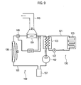
- the air conditioning system includes a heat-pump type cooling unit 100 and an air-heating circulation unit 120.
- the heat-pump type cooling unit 100 has a first circulation path 101 along which first refrigerant circulates.
- the air-heating circulation unit 120 has a second circulation path 121 along which second refrigerant circulates.
- a compressor 102, a heat-radiating side of an internal heat exchanger 103, an in-compartment heat exchanger 104, an expansion valve 105, an evaporator (external heat exchanger) 106 and a gas-liquid separator 107 are provided on the first circulation path 101 in the heat-pump type cooling unit 100.
- the in-compartment heat exchanger 104 is provided within an air-conditioning duct 110.
- a pump 122 for circulating the second refrigerant, a heat-receiving side of the internal heat exchanger 103 and a heater core 123 are provided on the second refrigerant path 121 in the air-heating circulation unit 120.
- the compressor of the heat-pump type cooling unit 100 and the pump 102 of the air-heating circulation unit 120 are both driven.
- Heat of the first refrigerant is radiated at the in-compartment heat exchanger 104 for air heating.
- the heat of the first refrigerant is conducted to the second refrigerant in the internal heat exchanger 103.
- heat of the second refrigerant is radiated at the heater core 123 for air heating.
- the cooling unit 100 is driven even at the heating mode and the first refrigerant needs to receive heat from flowing air at the evaporator 106.
- the first refrigerant is HFC134a
- evaporating pressure of the refrigerant is 1.01 bar (almost atmosphere pressure: 1 atm) at -26.2 deg C and 1.33 bar at -20.0 deg C as shown in Fig. 10 . Therefore, the pressure may be reduced by 0.32 Bar and then the pressure in the first circulation path 101 will be equal-to or lower-than the atmosphere pressure. And then, since the gas-liquid separator 107 is provided between the evaporator 106 and the compressor 102, the evaporator 106 cannot achieve heat-exchanging if flowing resistance through the gas-liquid separator 107 is equivalent to 0.32 bar. As a result, air heating cannot be achieved.
- An object of the present invention is to provide an air conditioning system that can achieve air-heating by driving a heat-pump type cooling unit even under a condition where outside temperature is very low.
- An aspect of the present invention is to provide an air conditioning system that includes a heat-pump type cooling unit including a first circulation path in which a first refrigerant circulates and an air-heating unit including a second circulation path in which a second refrigerant circulates.
- a compressor for compressing the first refrigerant, a condenser for heat-exchanging between the first refrigerant and the second refrigerant and radiating heat of the first refrigerant, an expansion unit for expanding the first refrigerant, and an evaporator for heat-exchanging between the first refrigerant expanded by the expansion unit and air to cool the air are provided on the first circulation path.
- the air-heating unit achieves air-heating by using heat radiated by the condenser.
- the system further includes a gas-liquid separator provided between the expansion unit and the evaporator for separating the first refrigerant supplied from the expansion unit into first refrigerant gas and first refrigerant liquid and sending the first refrigerant liquid to the evaporator, a bypass path for flowing the first refrigerant gas through the first circulation path with bypassing the evaporator, and a refrigerant liquid flow preventing unit for preventing the first refrigerant liquid from flowing into the evaporator.
- a gas-liquid separator provided between the expansion unit and the evaporator for separating the first refrigerant supplied from the expansion unit into first refrigerant gas and first refrigerant liquid and sending the first refrigerant liquid to the evaporator
- a bypass path for flowing the first refrigerant gas through the first circulation path with bypassing the evaporator
- a refrigerant liquid flow preventing unit for preventing the first refrigerant liquid from flowing into the evaporator.
- the first refrigerant liquid is prevented from flowing into the evaporator by the refrigerant liquid flow preventing unit and only the first refrigerant gas is circulated through the bypass path (the warming-up mode).
- the evaporator does not achieve heat-exchanging but heat quantity equivalent to work of the compressor is used for air-heating. Therefore, air-heating can be achieved even under a condition where outside temperature is very low.
- a pump for circulating the second refrigerant a component container for arranging the condenser also on the second circulation path, a heater core for heating air by heat-exchanging between the second refrigerant and the air, and a radiator for radiating heat of the second refrigerant are provided on the second circulation path.
- the second refrigerant is fluid to achieve heat-exchanging with sensible heat change
- air-heating can be done by way of heat-radiation by the heater core in a hearing mode and air-cooling can be done by way of heat-radiation by the radiator in a cooling mode.
- the condenser is a water-cooling type with higher heat-transfer efficiency than an air-cooling type, it can be down-sized and thereby flowing resistance of the first refrigerant can be reduced.
- driving force for the compressor can be saved and thereby the compressor can be down-sized.
- the refrigerant in the second circulation path does not change its phase in a liquid phase but takes sensible heat change, heat-transfer efficiency can be further improved and down-sizing can be achieved.
- a fist orifice and a second orifice are capable of provided on the bypass path alternatively.
- the refrigerant liquid flow preventing unit is a changeover valve capable of moving between a first position and a second position.
- the changeover valve When the changeover valve is set to the first position, the bypass path is communicated with the first circulation path and the first circulation path is blocked so as not to flow the first refrigerant liquid into the evaporator.
- the changeover valve When the changeover valve is set to the second position, the bypass path is communicated with the first circulation path and the first circulation path is opened so as to flow the first refrigerant liquid into the evaporator.
- the changeover valve has a first orifice to make the first refrigerant gas passing through at the first position and a second orifice to make the first refrigerant gas passing through at the first position.
- Flowing resistance of the first orifice is set to be optimum for warming-up mode and flowing resistance of the second orifice is set to be optimum for heating/cooling mode.
- the changeover valve is controlled so that the refrigerant gas passes through the fist orifice in the warm-up mode and passes through the second orifice in the heating/cooling mode.
- flow quantity of the refrigerant gas may be differentiated between the warming-up mode and the heating/cooling mode, appropriate flowing resistance can be set for each mode.
- bypass path passes through a position where the first refrigerant liquid is normally held within a refrigerant tank within the gas-liquid separator.
- the inside of the bypass path communicates with the inside of the refrigerant tank through an oil breed hole at the position.
- changeover between the warming-up mode (it is prevented that the first refrigerant liquid flows into the evaporator) and the heating mode (it is allowed that the refrigerant liquid flows into the evaporator) is done based on at least one of intake air temperature into the evaporator and refrigerant pressure at an inlet side of the compressor.
- mode changeover can be done appropriately by way of the mode changeover based on the intake air temperature of the evaporator.
- mode changeover can be done appropriately by way of the mode changeover based on the refrigerant pressure at the inlet side of the compressor.
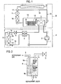
- an air conditioning system is combined of a heat-pump type cooling unit A and an air-heating circulation unit B.
- the heat-pump type cooling unit A includes a first circulation path 1.
- the first circulation path 1 is filled with first refrigerant (HFC134a).
- a compressor 2 a water-cooled condenser 3, an internal heat exchanger 4, an expansion valve (expansion unit) 5, a gas-liquid separator 6, an evaporator 7 and a changeover valve (refrigerant liquid flow preventing unit) 8 are provided on the first circulation path 1 in this order.
- the compressor 2 inhales the relatively low-temperature and pressure first refrigerant and discharges the high-temperature and pressure first refrigerant after compressing it.
- the water-cooled condenser 3 is arranged within an after-mentioned unit container 13 on the second circulation path 10.
- the first refrigerant output from the compressor 2 is cooled by the second refrigerant. Specifically, heat-exchanging is achieved between the first refrigerant and the second refrigerant at the water-cooled condenser 3.
- the second refrigerant is heated by the first refrigerant.
- the internal heat exchanger 4 achieves heat-exchanging between the first refrigerant output from the water-cooled condenser 3 and the low-temperature first refrigerant output from the evaporator 7.
- the first refrigerant output from the water-cooled condenser 3 is further cooled down.
- the expansion valve 5 expands the first refrigerant (reduce the pressure of the first refrigerant) had passed through the internal heat exchanger 4 and sends it to the gas-liquid separator 6 as a low-temperature and pressure gas.
- the gas-liquid separator 6 separates the first refrigerant output from the expansion valve 5 into gas phase and liquid phase.
- the first refrigerant in the liquid phase is temporally held in the gas-liquid separator 6. Detailed configuration of the gas-liquid separator 6 will be explained later in detail.
- the evaporator 7 achieves heat-exchanging between the first refrigerant liquid output from the gas-liquid separator 6 and air had passed through the evaporator 7.
- the air had passed through the evaporator 7 is cooled down by the first refrigerant.
- the evaporator 7 is provided within an air-conditioning duct 30 as explained later.
- the changeover valve 8 changes over the flow of the first refrigerant to make the first refrigerant flow into the evaporator 7 or not. Detailed configuration of the changeover valve 8 will be explained later in detail.
- a bypass path 9 for the refrigerant gas is provided in the first circulation path 1 so as to communicate the gas-liquid separator 6 and the changeover valve 8.
- the air-heating circulation unit B includes a second circulation path 10.
- the second circulation path 10 is filled with second refrigerant (liquid such as water, antifreeze solution or the like).
- a pump 11, a radiator 12, the unit container 13 and a heater core 14 are provided on the second circulation path 10 in this order.
- the unit container 13 is a space having a larger cross-sectional area than that of the second circulation path 10.
- the above-mentioned water-cooled condenser 3 and an electric heater 15 are contained within the unit container 13.
- the pump 11 inhales the second refrigerant and then pumps it out in order to circulates it along the second circulation path 10.
- the second refrigerant liquid pumped by the pump 11 circulates along the second circulation path 10 in liquid phase without changing its phase.
- the second refrigerant takes sensible heat change due to heat-changing.
- the radiator 12 is a unit for radiating heat of the second refrigerant to fresh air.
- the fresh air is blown to the radiator 12 by an electric fan or air flow due to a vehicle running and then heat-exchange is achieved between the second refrigerant and the fresh air.
- the electric heater 15 is provided beneath the water-cooled condenser 13 and heats the second refrigerant by its heat with being energized.
- the heater core 14 heats air passing through it by achieving heat-exchanging between the second refrigerant and the air passing through it.
- the heater core 14 is provided within the air-conditioning duct 30.
- a radiator-bypass path 16 is provided in the second circulation path 10 so as to bypass the radiator 12.
- the flow of the second refrigerant can be changed into the radiator 12 or the radiator-bypass path 16 by changing over a flow-path changeover valve 17 provided upstream of the radiator 12.
- the gas-liquid separator 6 has a refrigerant tank 6a within its inside as shown in Fig. 2 .
- a refrigerant inlet 1a is connected at an upper portion of the refrigerant tank 6a.
- the refrigerant inlet 1a configures a part of the first circulation path 1.
- a refrigerant outlet opening 1b is opened at a lower portion of the refrigerant tank 6a.
- the refrigerant outlet 1b is connected to the evaporator 7 and configures a part of the first circulation path 1.
- the refrigerant liquid is output from the refrigerant outlet 1b to the evaporator 7.
- the bypass path 9 for the refrigerant gas is also connected at the upper portion of the refrigerant tank 6a.
- the refrigerant gas is output through the bypass path 9 to the changeover valve 8.
- the bypass path 9 is led out of the refrigerant tank 6a via the lower portion of the refrigerant tank 6a and a position where the refrigerant liquid is normally held.
- the inside of the bypass path 9 communicates with the inside of the refrigerant tank 6a through an oil breed hole 9a at the position where the refrigerant liquid is held.
- the changeover valve 8 has a valve housing 20 as shown in Figs. 3A and 3B .
- the first circulation path 1A from the evaporator 7 (“1A" is allocated for distinction in Figs. 3A and 3B ) and the bypass path 9 are connected to two inlet ports of the valve housing 20, respectively.
- the first circulation path 1B led out to the compressor 2 (“1B" is allocated for distinction in Figs. 3A and 3B ) is connected to two outlet ports of the valve housing 20.
- a valve element 21 is provided within the valve housing 20.
- the valve element 21 includes a path 22 for the refrigerant liquid.
- the valve element 21 also includes a first orifice 23 and a second orifice 24 for the refrigerant gas.
- the first orifice 23 has a smaller inner diameter than that of the second orifice 24.
- the first orifice 23 provides large flowing resistance and the second orifice 24 provides small flowing resistance.
- the flowing resistance of the first orifice 23 is set to be optimum for warming-up mode and the second orifice 24 is set to be optimum for heating/cooling mode.
- the valve element 21 moves between a first position ( Fig. 3A ) and a second position ( Fig. 3B ) according to a changeover command from a controller.
- the refrigerant liquid flowing between the first circulation path 1A and the first circulation path 1B is blocked and the refrigerant gas flowing between the bypass path 9 and the first circulation path 1B is allowed through the first orifice 23. Therefore, the refrigerant liquid does not flow into the evaporator 7 and only the refrigerant gas circulates in the refrigeration cycle.
- the refrigerant liquid flowing between the first circulation path 1A and the first circulation path 1B is allowed and the refrigerant gas flowing between the bypass path 9 and the first circulation path 1B is also allowed through the second orifice 24. Therefore, the refrigerant liquid flows into the evaporator 7 and the refrigerant gas circulates in the refrigeration cycle with bypassing the evaporator 7 through the bypass path 9.
- An air selector door (not shown) and a blower fan 31 are provided within the air-conditioning duct 30 in this order.
- the air selector door is changed its position between an interior-air position for inhaling air inside a vehicle compartment (interior air) and a fresh-air position for inhaling air outside the vehicle compartment (fresh air).
- Interior air or fresh air is inhaled into the air conditioning duct 30 by flowing force of the blower fan 31.
- the evaporator 7 and the heater core 14 is further provider within the air-conditioning duct 30 in this order.
- a temperature sensor 32 is provided just upstream the evaporator 7. The temperature sensor 32 detects air temperature before passing through the evaporator 7 (intake air temperature) to output it to the controller 40 (see Fig. 5 ).
- a mixture door 33 is provided between the evaporator 7 and the heater core 14. The mixture door 33 adjusts how much rate of cooled air from the evaporator 7 to be sent to the heater core 14. In warming-up mode, full heating mode and so on, entire air passing through the evaporator 7 is sent to the heater core 14. Air passing-through and bypassing the heater core 14 is blown out from desired ventilation grills.
- an input command (heating operation command, cooling operation command or the like) from a operation unit 41 and a detection signal of the temperature sensor 32 are input to the controller 40.
- the controller 40 controls the compressor 2, the pump 11, door actuators 42, the changeover valve 8, the electric heater 15, the flow-path changeover valve 17 and so on based on the input command by a user, detection information of the temperature sensor 32 or the like.
- the door actuators 42 actuate the air selector door (not shown), the mixture door 33 and so on.
- the controller 40 drives the door actuators 42 to move the mixture door 33 to the position so that entire cooled air from the evaporator 7 will be sent to the heater core 14 ( Fig. 4 ) and to move the air selector door (not shown) to the interior-air position.
- the controller 40 drives the compressor 2 and the pump 11 and controls the flow-path changeover valve 17 so as to flow the refrigerant to the radiator-bypass path 16.
- the controller 40 gets the detected temperature by the temperature sensor 32 parallel to the above controls.
- the changeover valve 8 is set to the first position ( Fig. 3A ) to achieve the warming-up mode when the detected temperature by the temperature sensor 32 is not more than a predetermined temperature (e.g. -20 deg C). Basically the detected temperature by the temperature sensor 32 at starting-up may be equal to outside temperature.
- the first refrigerant in the heat-pump type cooling unit A is separated into gas phase (refrigerant gas) and liquid phase (refrigerant liquid) by the gas-liquid separator 6.
- the refrigerant liquid does not flow into the evaporator 7 and only the refrigerant gas circulates in the refrigeration cycle with bypassing the evaporator 7 through the bypass path 9 as shown in Fig. 6 . Therefore, the first refrigerant is heated by heat quantity equivalent to work of the compressor 2 and heat of the first refrigerant is radiated at the water-cooled condenser 3.
- the second refrigerant in the air-heating circulation unit B is heated by heat-radiation at the water-cooled condenser 3 and heat of the second refrigerant is radiated at the heater core 14 to heat flowing air within the air-conditioning duct 30.
- the heated air by the heater core 14 is blown out into a vehicle compartment.
- the vehicle compartment can be heated by using the heat-pump type cooling unit A regardless of outside temperature.
- the controller 40 continuously checks the detected temperature by the temperature sensor 32 and changes the changeover valve 8 to the second position ( Fig. 3B ) to achieve the heating mode when the detected temperature becomes more than the predetermined temperature (e.g. -20 deg C) to .
- the predetermined temperature e.g. -20 deg C
- the first refrigerant in the heat-pump type cooling unit A is separated into gas phase (refrigerant gas) and liquid phase (refrigerant liquid) by the gas-liquid separator 6.
- the refrigerant liquid flows into the evaporator 7 and the refrigerant gas circulates in the refrigeration cycle with bypassing the evaporator 7 through the bypass path 9 as shown in Fig. 7 . Therefore, the first refrigerant is heated by heat quantity equivalent to work of the compressor 2 and condensation of the first refrigerant. Then, heat of the first refrigerant is radiated at the water-cooled condenser 3.
- the second refrigerant in the air-heating circulation unit B is heated by heat-radiation at the water-cooled condenser 3 and heat of the second refrigerant is radiated at the heater core 14 to heat flowing air within the air-conditioning duct 30.
- the heated air by the heater core 14 is blown out into a vehicle compartment.
- the refrigerant liquid output from the gas-liquid separator 6 flows into the evaporator 7 for heat-exchanging at the evaporator 7.
- a refrigerant evaporating pressure at an outlet port of the evaporator 7 can be reduced by a pressure equivalent to flowing resistance reduction due to the gas-liquid separator 6 (between the orifices 23 and 24) and bypassing the evaporator 7 as shown in Fig. 8 compared with the conventional system where a gas-liquid separator is provided between an evaporator and a compressor. Therefore, temperature difference between the first refrigerant and the air passing through the evaporator 7 even under a very low temperature condition (e.g. almost -20 deg C) can be made larger than the conventional system.
- a very low temperature condition e.g. almost -20 deg C
- an evaporating temperature of the first refrigerant must be -20 deg C at least as shown in Fig. 10 . Therefore, heat-exchanging for air-heating cannot be achieved if air temperature before passing through the evaporator (intake air temperature) is -20 deg C.
- an evaporating temperature of the first refrigerant can be -26.2 deg C at least in the present embodiment as shown in Fig. 8 . Heat-exchanging for air-heating can be achieved even if the air temperature before passing through the evaporator 7 (intake air temperature) is -20 deg C.
- the flow-path changeover valve 17 is changed so as to flow the refrigerant to the radiator 12. Therefore, heat of the first refrigerant is radiated outside the vehicle compartment by the radiator 12.
- the mixture door 33 is moved to a position for restricting a flow amount to the heater core 14. Then, the first refrigerant cools flowing air within the air-conditioning duct 30 by the evaporator. Cooled air air-conditioned with the cooled air by the evaporator 7 and/or heated air passing through the heater core 14 is supplied into the vehicle compartment.
- the pump 11 for circulating the second refrigerant, the component container 13 for arranging the water-cooled condenser 3 on the second circulation path 10, the heater core 14 for heating air by heat-exchanging between the second refrigerant and the air, the radiator 12 for radiating heat of the second refrigerant are provided, and the second refrigerant is fluid to achieve heat-exchanging with sensible heat change. Therefore, air-heating and air-cooling can be done by way of the heat-radiation by the heater core 14 in the hearing mode and by the radiator 12 in the cooling mode.
- the condenser 3 is a water-cooling type with higher heat-transfer efficiency than an air-cooling type, it can be down-sized and thereby flowing resistance of the first refrigerant can be reduced. As a result, since needed power for driving the compressor 2 can be reduced by the flowing resistance reduction, driving force for the compressor 2 can be saved and thereby the compressor can be down-sized. Furthermore, since the refrigerant in the second circulation path 10 does not change its phase in a liquid phase but takes sensible heat change, heat-transfer efficiency can be further improved and down-sizing can be achieved.
- the refrigerant liquid flow preventing unit is the changeover valve 8 which can be changed over between the first position and the second position.
- the changeover valve 8 When the changeover valve 8 is set to the first position, the bypass path 9 is communicated with the first circulation path 1 and the refrigerant flowing between the first circulation path 1A and the first circulation path 1B (see Figs. 3A and 3B ) is blocked so as not to flow the refrigerant into the evaporator 7.
- the changeover valve 8 is set to the second position, the bypass path 9 is communicated with the first circulation path 1 and the refrigerant flowing between the first circulation path 1A and the first circulation path 1B (see Figs. 3A and 3B ) is allowed so as to flow the refrigerant into the evaporator 7. Therefore, since operation mode (between the warming-up mode and the heating/cooling mode) can be changed over by way of changeover control of the changeover valve 8, changeover operation can be done easily.
- the first orifice 23 and the second orifice 24 are provided on the bypass path 9 (specifically within the changeover valve 8). Even if the refrigerant liquid flows through the bypass path 9, the refrigerant liquid is gasified again. Therefore, it can be prevented that the refrigerant liquid returns to the compressor 2.
- the changeover valve 8 includes the first orifice 23 for allowing the refrigerant gas flowing at its first position and the second orifice 24 for allowing the refrigerant gas flowing at its second position.
- the flowing resistance of the first orifice 23 is set adequately for the warming-up mode.
- the flowing resistance of the second orifice 24 is set adequately for the heating/cooling mode.
- flow quantity of the refrigerant gas may be differentiated between the warming-up mode and the heating/cooling mode, appropriate flowing resistance can be set for each mode.
- the bypass path 9 passes through a position where the refrigerant liquid is normally held within the refrigerant tank 6a of the gas-liquid separator 6 and the inside of the bypass path 9 communicates with the inside of the refrigerant tank 6a through the oil breed hole 9a at the position. Therefore, since oil is circulated together with the refrigerant gas downstream the bypass path 9, the oil can be returned to the compressor 2 even in the warming-up mode. As a result, reliability of the compressor 2 can be ensured.
- changeover between the warming-up mode (it is prevented that the refrigerant liquid flows into the evaporator 7) and the heating mode (it is allowed that the refrigerant liquid flows into the evaporator 7) is done based on the intake air temperature. Since it depends on the intake air temperature of the evaporator 7 whether or not the evaporator 7 can done appropriate heat-exchanging, mode changeover can be done appropriately by way of the mode changeover based on the intake air temperature of the evaporator 7.
- changeover control between the warm-up mode and the heating mode may be done based on the refrigerant pressure at the inlet side of the compressor 2. Since it depends on the refrigerant pressure at the inlet side of the compressor 2 whether or not the refrigerant pressure at the inlet side of the compressor 2 is equal-to or lower-than the atmosphere pressure, mode changeover can be done appropriately by way of the mode changeover based on the refrigerant pressure at the inlet side of the compressor 2. Note that changeover between the warming-up mode and the heating mode may be done based on both the intake air temperature of the evaporator 7 and the refrigerant pressure at the inlet side of the compressor 2.
- entire of the cooled air passing through the evaporator 7 is returned to the vehicle compartment in the heating mode.
- entire or some of the cooled air passing through the evaporator 7 may be ejected outside the vehicle compartment.
- heating performance can be improved.
- the electric heater 15 is used.
- the same workings and advantages can be achieved by a combustion heater or the like.
- HFC134a is used as the first refrigerant and water, antifreeze solution or the like is used as the second refrigerant.
- Other refrigerant may be used.
Landscapes
- Engineering & Computer Science (AREA)
- Physics & Mathematics (AREA)
- Mechanical Engineering (AREA)
- Thermal Sciences (AREA)
- General Engineering & Computer Science (AREA)
- Air-Conditioning For Vehicles (AREA)
Applications Claiming Priority (1)
| Application Number | Priority Date | Filing Date | Title |
|---|---|---|---|
| JP2008033718A JP2009190579A (ja) | 2008-02-14 | 2008-02-14 | 空気調和システム |
Publications (1)
| Publication Number | Publication Date |
|---|---|
| EP2090852A2 true EP2090852A2 (fr) | 2009-08-19 |
Family
ID=40677738
Family Applications (1)
| Application Number | Title | Priority Date | Filing Date |
|---|---|---|---|
| EP09000435A Withdrawn EP2090852A2 (fr) | 2008-02-14 | 2009-01-14 | Système de climatisation |
Country Status (3)
| Country | Link |
|---|---|
| US (1) | US20090205350A1 (fr) |
| EP (1) | EP2090852A2 (fr) |
| JP (1) | JP2009190579A (fr) |
Cited By (3)
| Publication number | Priority date | Publication date | Assignee | Title |
|---|---|---|---|---|
| CN103256744A (zh) * | 2013-04-18 | 2013-08-21 | 南京瑞柯徕姆环保科技有限公司 | 一种复叠式冷力循环制冷装置(高压侧) |
| US20220369509A1 (en) * | 2021-05-12 | 2022-11-17 | Huawei Digital Power Technologies Co., Ltd. | Cooling device |
| CN116367495A (zh) * | 2023-03-02 | 2023-06-30 | 珠海格力电器股份有限公司 | 一种功率模块的换热系统及其控制方法 |
Families Citing this family (13)
| Publication number | Priority date | Publication date | Assignee | Title |
|---|---|---|---|---|
| EP2593318A1 (fr) | 2010-07-14 | 2013-05-22 | International Truck Intellectual Property Company, LLC | Système de climatisation pour l'intérieur d'un véhicule à propulsion électrique |
| KR101342931B1 (ko) * | 2011-03-09 | 2013-12-18 | 한라비스테온공조 주식회사 | 차량용 히트 펌프 시스템 |
| DE102012108886B4 (de) | 2012-09-20 | 2019-02-14 | Hanon Systems | Wärmeübertrageranordnung und Klimatisierungssystem eines Kraftfahrzeuges |
| CN103256743B (zh) * | 2013-04-18 | 2015-03-04 | 南京瑞柯徕姆环保科技有限公司 | 一种复叠式冷力循环制冷装置(低压侧) |
| JP2015186989A (ja) * | 2014-03-12 | 2015-10-29 | カルソニックカンセイ株式会社 | 車載温調装置、車両用空調装置及びバッテリ温調装置 |
| SG10201405411QA (en) * | 2014-09-02 | 2016-04-28 | Cyclect Electrical Engineering Pte Ltd | Heat recovery system and method |
| EP3246222B1 (fr) * | 2015-01-13 | 2022-12-28 | Mitsubishi Electric Corporation | Système de climatisation de véhicule |
| US10996000B2 (en) * | 2015-11-04 | 2021-05-04 | Toyota Motor Engineering & Manufacturing North America, Inc. | Absorption-based system for automotive waste heat recovery |
| JP6782013B2 (ja) * | 2017-02-03 | 2020-11-11 | 宏和工業株式会社 | 冷却ユニット |
| DE102018114762B4 (de) * | 2017-07-10 | 2023-12-28 | Hanon Systems | Verfahren zum Betreiben einer Klimaanlage eines Kraftfahrzeuges |
| CN107521307B (zh) * | 2017-09-29 | 2018-05-15 | 爱驰汽车有限公司 | 汽车热管理系统及具有该系统的汽车 |
| US11592221B2 (en) | 2020-12-22 | 2023-02-28 | Deere & Company | Two-phase cooling system |
| CN117267816B (zh) * | 2023-11-03 | 2024-07-16 | 蓝航科技(廊坊)集团有限公司 | 一种高效节能稳定的中央空调旁通系统及智能旁通阀门 |
Citations (1)
| Publication number | Priority date | Publication date | Assignee | Title |
|---|---|---|---|---|
| JP2002098430A (ja) | 2000-07-21 | 2002-04-05 | Nippon Soken Inc | ヒートポンプサイクル |
Family Cites Families (7)
| Publication number | Priority date | Publication date | Assignee | Title |
|---|---|---|---|---|
| FR2762592B1 (fr) * | 1997-04-24 | 1999-06-18 | Elf Aquitaine | Procede d'elimination des composes soufres h2s, so2, cos et/ou cs2 contenus dans un gaz residuaire d'usine a soufre avec recuperation desdits composes sous la forme de soufre |
| JPH1130445A (ja) * | 1997-07-10 | 1999-02-02 | Denso Corp | 冷凍サイクル装置 |
| JP3952545B2 (ja) * | 1997-07-24 | 2007-08-01 | 株式会社デンソー | 車両用空調装置 |
| US6105386A (en) * | 1997-11-06 | 2000-08-22 | Denso Corporation | Supercritical refrigerating apparatus |
| DE50212488D1 (de) * | 2001-12-21 | 2008-08-21 | Daimler Ag | Aufbau und regelung einer klimaanlage für ein kraftfahrzeug |
| CN1610809A (zh) * | 2002-03-28 | 2005-04-27 | 松下电器产业株式会社 | 制冷循环装置 |
| DE102004002445A1 (de) * | 2004-01-16 | 2005-08-11 | Webasto Ag | Klimagerät zur Standklimatisierung eines Fahrzeugs |
-
2008
- 2008-02-14 JP JP2008033718A patent/JP2009190579A/ja active Pending
-
2009
- 2009-01-14 EP EP09000435A patent/EP2090852A2/fr not_active Withdrawn
- 2009-02-03 US US12/364,899 patent/US20090205350A1/en not_active Abandoned
Patent Citations (1)
| Publication number | Priority date | Publication date | Assignee | Title |
|---|---|---|---|---|
| JP2002098430A (ja) | 2000-07-21 | 2002-04-05 | Nippon Soken Inc | ヒートポンプサイクル |
Cited By (4)
| Publication number | Priority date | Publication date | Assignee | Title |
|---|---|---|---|---|
| CN103256744A (zh) * | 2013-04-18 | 2013-08-21 | 南京瑞柯徕姆环保科技有限公司 | 一种复叠式冷力循环制冷装置(高压侧) |
| US20220369509A1 (en) * | 2021-05-12 | 2022-11-17 | Huawei Digital Power Technologies Co., Ltd. | Cooling device |
| US12274029B2 (en) * | 2021-05-12 | 2025-04-08 | Huawei Digital Power Technologies Co., Ltd. | Cooling device |
| CN116367495A (zh) * | 2023-03-02 | 2023-06-30 | 珠海格力电器股份有限公司 | 一种功率模块的换热系统及其控制方法 |
Also Published As
| Publication number | Publication date |
|---|---|
| US20090205350A1 (en) | 2009-08-20 |
| JP2009190579A (ja) | 2009-08-27 |
Similar Documents
| Publication | Publication Date | Title |
|---|---|---|
| EP2090852A2 (fr) | Système de climatisation | |
| JP4505510B2 (ja) | 車両用空調システム | |
| US11254190B2 (en) | Vapor injection heat pump and control method | |
| EP2090448A1 (fr) | Système de climatisation pour véhicule | |
| US12558939B2 (en) | Thermal conditioning system | |
| EP2088013A1 (fr) | Système de climatisation pour véhicule | |
| CN103270377B (zh) | 热交换系统 | |
| US20190202265A1 (en) | Method of heating and cooling at least one zone of a passenger compartment of a vehicle | |
| CN102692100A (zh) | 热交换系统和车辆制冷循环系统 | |
| JP2002354608A (ja) | 電気自動車のバッテリ冷却装置 | |
| JP2010013044A (ja) | 車両用空気調和システム | |
| US10611212B2 (en) | Air conditioner for vehicle | |
| JP7361178B1 (ja) | 車両用温調システム | |
| JP2010012949A (ja) | 車両用空気調和システム | |
| KR20200062682A (ko) | 전기자동차용 냉난방 시스템 | |
| JP5096956B2 (ja) | 車両用空気調和システム | |
| JP2009184494A (ja) | 車両用空気調和システム | |
| JP5117944B2 (ja) | 車両用空気調和システム | |
| JP2009202773A (ja) | 車両用空気調和システム | |
| US20250222743A1 (en) | Thermal management system for a vehicle | |
| JP2002225545A (ja) | 車両用空調装置 | |
| US10513166B2 (en) | Vehicle HVAC system with auxiliary coolant loop for heating and cooling vehicle interior | |
| JP7097345B2 (ja) | 車両用空調装置 | |
| JP2020516519A (ja) | 2つのダクトを備える換気、暖房、及び/又は、空調設備 | |
| JP2002544032A (ja) | 加熱および空調装置 |
Legal Events
| Date | Code | Title | Description |
|---|---|---|---|
| PUAI | Public reference made under article 153(3) epc to a published international application that has entered the european phase |
Free format text: ORIGINAL CODE: 0009012 |
|
| AK | Designated contracting states |
Kind code of ref document: A2 Designated state(s): AT BE BG CH CY CZ DE DK EE ES FI FR GB GR HR HU IE IS IT LI LT LU LV MC MK MT NL NO PL PT RO SE SI SK TR |
|
| AX | Request for extension of the european patent |
Extension state: AL BA RS |
|
| STAA | Information on the status of an ep patent application or granted ep patent |
Free format text: STATUS: THE APPLICATION HAS BEEN WITHDRAWN |
|
| 18W | Application withdrawn |
Effective date: 20100312 |