EP2090858B1 - Wärmetauscher - Google Patents
Wärmetauscher Download PDFInfo
- Publication number
- EP2090858B1 EP2090858B1 EP09001426A EP09001426A EP2090858B1 EP 2090858 B1 EP2090858 B1 EP 2090858B1 EP 09001426 A EP09001426 A EP 09001426A EP 09001426 A EP09001426 A EP 09001426A EP 2090858 B1 EP2090858 B1 EP 2090858B1
- Authority
- EP
- European Patent Office
- Prior art keywords
- coil
- heat exchanger
- section
- cross
- ventilation
- Prior art date
- Legal status (The legal status is an assumption and is not a legal conclusion. Google has not performed a legal analysis and makes no representation as to the accuracy of the status listed.)
- Active
Links
Images
Classifications
-
- F—MECHANICAL ENGINEERING; LIGHTING; HEATING; WEAPONS; BLASTING
- F28—HEAT EXCHANGE IN GENERAL
- F28D—HEAT-EXCHANGE APPARATUS, NOT PROVIDED FOR IN ANOTHER SUBCLASS, IN WHICH THE HEAT-EXCHANGE MEDIA DO NOT COME INTO DIRECT CONTACT
- F28D1/00—Heat-exchange apparatus having stationary conduit assemblies for one heat-exchange medium only, the media being in contact with different sides of the conduit wall, in which the other heat-exchange medium is a large body of fluid, e.g. domestic or motor car radiators
- F28D1/02—Heat-exchange apparatus having stationary conduit assemblies for one heat-exchange medium only, the media being in contact with different sides of the conduit wall, in which the other heat-exchange medium is a large body of fluid, e.g. domestic or motor car radiators with heat-exchange conduits immersed in the body of fluid
- F28D1/04—Heat-exchange apparatus having stationary conduit assemblies for one heat-exchange medium only, the media being in contact with different sides of the conduit wall, in which the other heat-exchange medium is a large body of fluid, e.g. domestic or motor car radiators with heat-exchange conduits immersed in the body of fluid with tubular conduits
- F28D1/047—Heat-exchange apparatus having stationary conduit assemblies for one heat-exchange medium only, the media being in contact with different sides of the conduit wall, in which the other heat-exchange medium is a large body of fluid, e.g. domestic or motor car radiators with heat-exchange conduits immersed in the body of fluid with tubular conduits the conduits being bent, e.g. in a serpentine or zig-zag
- F28D1/0472—Heat-exchange apparatus having stationary conduit assemblies for one heat-exchange medium only, the media being in contact with different sides of the conduit wall, in which the other heat-exchange medium is a large body of fluid, e.g. domestic or motor car radiators with heat-exchange conduits immersed in the body of fluid with tubular conduits the conduits being bent, e.g. in a serpentine or zig-zag the conduits being helically or spirally coiled
- F28D1/0473—Heat-exchange apparatus having stationary conduit assemblies for one heat-exchange medium only, the media being in contact with different sides of the conduit wall, in which the other heat-exchange medium is a large body of fluid, e.g. domestic or motor car radiators with heat-exchange conduits immersed in the body of fluid with tubular conduits the conduits being bent, e.g. in a serpentine or zig-zag the conduits being helically or spirally coiled the conduits having a non-circular cross-section
-
- F—MECHANICAL ENGINEERING; LIGHTING; HEATING; WEAPONS; BLASTING
- F28—HEAT EXCHANGE IN GENERAL
- F28D—HEAT-EXCHANGE APPARATUS, NOT PROVIDED FOR IN ANOTHER SUBCLASS, IN WHICH THE HEAT-EXCHANGE MEDIA DO NOT COME INTO DIRECT CONTACT
- F28D7/00—Heat-exchange apparatus having stationary tubular conduit assemblies for both heat-exchange media, the media being in contact with different sides of a conduit wall
- F28D7/02—Heat-exchange apparatus having stationary tubular conduit assemblies for both heat-exchange media, the media being in contact with different sides of a conduit wall the conduits being helically coiled
- F28D7/024—Heat-exchange apparatus having stationary tubular conduit assemblies for both heat-exchange media, the media being in contact with different sides of a conduit wall the conduits being helically coiled the conduits of only one medium being helically coiled tubes, the coils having a cylindrical configuration
-
- F—MECHANICAL ENGINEERING; LIGHTING; HEATING; WEAPONS; BLASTING
- F28—HEAT EXCHANGE IN GENERAL
- F28F—DETAILS OF HEAT-EXCHANGE AND HEAT-TRANSFER APPARATUS, OF GENERAL APPLICATION
- F28F2265/00—Safety or protection arrangements; Arrangements for preventing malfunction
- F28F2265/18—Safety or protection arrangements; Arrangements for preventing malfunction for removing contaminants, e.g. for degassing
Definitions
- the invention relates to a heat exchanger according to the preamble of patent claim 1.
- a heat exchanger of the type mentioned is according to the DE 200 09 560 U1 known. This consists of a liquid heat transfer medium leading, helically coiled coiled tubing with a horizontally oriented helical axis and with one above and one below the helix axis coiled tube part.
- supply and return connections are provided on the outer circumference of the coiled tubing, on the one hand serve for venting and removal of the heat transfer medium on the other hand also for venting.
- This heat exchanger is part of a boiler, ie it encloses a combustion chamber with a burner producing an exhaust gas, wherein the exhaust gas flows through flow gaps of the coiled tubing and thereby emits its heat to the liquid heat transfer medium.
- the invention has for its object to provide for a tube-like heat exchanger with horizontal helical axis for the best possible ventability, regardless of whether this heat exchanger has the above-described flow and return ports or not.
- heat exchanger of the type mentioned by the features listed in the characterizing part of patent claim 1. It should be noted that the heat exchanger according to the invention is not limited to the application in a boiler, but rather, for example, in hot water tanks can be used (in this case, the heat exchanger is not of an exhaust gas of a burner, but flows around to be heated water), where also the problem of deteriorated heat transfer can occur by gas entry.
- the coiled tubing has a two-part flow cross-section, the first, larger flow cross-section being provided for the heat transfer medium and the second, smaller flow cross-section being designed as bleeding helix, wherein this helix per helix travel is at least one in the area of the helix part located above the helical axis Having the first connected to the second flow cross-section vent opening.
- the proviso of a "two-part flow cross-section" includes both the possibility of a one-piece tube coil in principle with two flow spaces and the possibility that another component is introduced into the coiled tubing.
- an additional coiled tubing (venting coil) is arranged in the coiled tube, wherein the per vent preferably provided in the uppermost area vent allows escape of possibly accumulated air or gas.
- venting coil should be smaller cross section than the coiled tubing is on the one hand mandatory, otherwise they could not be arranged in the coiled tubing, on the other hand, this proviso but also means that especially the gas and only very small parts Heat transfer medium can flow through the vent coil. This will be discussed in more detail below.
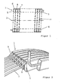
- FIG. 1 First, a highly abstracted embodiment of the heat exchanger according to the invention is shown. This exists (but this also applies to the embodiments according to FIGS. 2 to 4 ) from a liquid heat transfer medium leading, an approximately rectangular flow cross-section having coiled tubing 1 with a horizontally oriented helical axis 2 and with one above and below the helix axis 2 coiled tube part 3, 4.
- the coiled tubing is helically wound formed.
- it serves as a heat exchanger in a boiler, it has fürströmspalte 10 (indicated by dashed lines) through which flows the hot exhaust gas of a burner and thereby heats the heat transfer medium in the coiled tubing.
- the coiled tubing 1 has a two-part flow cross-section, wherein the first, larger flow cross section 5 is provided for the heat transfer medium and the second, smaller flow cross section 6 is formed as a bleed helix 7, wherein this per helical gear in the region above Has spiral axis 2 located coiled tubing part 3 at least one of the first with the second flow cross-section 5, 6 connecting the vent opening 8.
- vent openings 8 could in this case have been produced, for example, by double drilling through the coiled tubing and then welding the outer opening.
- the venting opening 8 has a cross-sectional area which is smaller than the flow-through cross section 6 of the venting spiral 7. Further, since the flow area 5 for the heat transfer medium is greater than the flow cross-section 6 of the venting coil 7, it follows that the cross-section of the vent opening 8 is preferably much smaller than the flow area 5 for the heat transfer medium. This proviso leads to a pressure gradient within the heat exchanger, so that on the one hand good ventilation is ensured, but on the other hand, only a very small loss of heat transfer medium via the vent coil results.
- the flow cross-section 6 of the venting helix 7 is circular and the vent 8 itself is formed as a circular bore.
- the venting coil 7 for example, rectangular
- the vent opening 8 for example, slit-shaped
- a tubular helix with a simple borehole or even several boreholes is (obviously) easiest to produce.
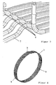
- venting coil 7 In order to ensure a secure positioning of the venting coil 7 within the coiled tubing 1, in particular with reference to FIG. 4 preferably provided that the helically wound venting coil 7 distributed over its circumference preferably three radially outwardly facing, inside of the coiled tubing 1 supporting bulges 9 has.
- the outer diameter of the venting spiral 7 defined by the bulges 9 corresponds approximately to the inner outer diameter of the flow cross section 5 for the heat transfer medium, ie after screwing in the venting coil 7, this is supported on the inner wall of the coiled tubing 1 so that the position of the venting coil 7 is within the coiled tubing 1 always remains safe, which is particularly important in relation to the position of the vent opening 8, since the venting of the heat exchanger, of course, works best when the vent 8 is located at the very top within the coiled tubing 1, and this is accordingly preferred in that one of the bulges 9 is arranged in the uppermost region of the upper coiled tubing part 3 and the vent opening 8 is arranged on the latter (cf. FIG. 2 and 3 ).
- the heat exchanger according to the invention or in particular the venting technology according to the invention functions as follows:
- the reinstallation of a boiler with a horizontally oriented heat exchanger it follows that in the heat transfer medium dissolved gas (in particular air) due to gravity accumulates at the highest point within the coiled tubing 1.
- the venting coil 7 with a vent opening 8 is arranged especially at this point, the gas can be discharged via the venting coil 7, for which purpose it is brought into contact with the environment of the heat exchanger at least temporarily (for example with a quick-vent valve).
- the pressure in the heat transfer medium ensures that excess gas is discharged via the vent 8 and the vent coil 7 from the heat exchanger and there no longer disturbs the heat transfer.
- the heat exchanger according to the invention is characterized by the screwed-in all helical or venting bleeder by an extremely efficient ventilation process, wherein This simple quick-venting can be carried out optionally at commissioning of the heat exchanger, but of course also at any time later and again and again.
- venting helix conforms to the FIG. 2 at least initially designed so that screwing is possible without hindrance.
- At least one end of the venting coil must be open during the venting process against an environment having a lower pressure level than the heat transfer medium.
Landscapes
- Engineering & Computer Science (AREA)
- Physics & Mathematics (AREA)
- Thermal Sciences (AREA)
- Mechanical Engineering (AREA)
- General Engineering & Computer Science (AREA)
- Heat-Exchange Devices With Radiators And Conduit Assemblies (AREA)
- Separation By Low-Temperature Treatments (AREA)
- Power Steering Mechanism (AREA)
- Compression-Type Refrigeration Machines With Reversible Cycles (AREA)
Description
- Die Erfindung betrifft einen Wärmetauscher gemäß dem Oberbegriff des Patentanspruchs 1.
- Ein Wärmetauscher der eingangs genannten Art ist nach der
DE 200 09 560 U1 bekannt. Dieser besteht aus einer ein flüssiges Wärmeträgermedium führenden, schraubenlinienartig gewickelten Rohrwendel mit einer horizontal orientiert ausgerichteten Wendelachse und mit einem oberhalb und einem unterhalb der Wendelachse befindlichen Rohrwendelteil. Bei diesem Wärmetauscher sind am äußeren Umfang der Rohrwendel Vor- und Rücklaufanschlüsse vorgesehen, die einerseits zur Zu- und Abführung des Wärmeträgermediums andererseits aber auch zur Entlüftung dienen. Dieser Wärmetauscher ist Teil eines Heizkessel, d. h. er umschließt eine Brennkammer mit einem ein Abgas erzeugenden Brenner, wobei das Abgas durch Strömungsspalte der Rohrwendel strömt und dabei seine wärme an das flüssige Wärmeträgermedium abgibt. - Der Erfindung liegt die Aufgabe zugrunde, bei einem rohrwendelförmigen Wärmetauscher mit horizontaler Wendelachse für eine möglichst gute Entlüftbarkeit zu sorgen, und zwar unabhängig davon, ob dieser Wärmetauscher die oben beschriebenen Vor- und Rücklaufanschlüsse aufweist oder nicht.
- Diese Aufgabe ist mit einem Wärmetauscher der eingangs genannten Art durch die im Kennzeichen des Patentanspruchs 1 aufgeführten Merkmale gelöst. Dabei ist festzuhalten, dass der erfindungsgemäße Wärmetauscher nicht auf die Anwendung in einem Heizkessel beschränkt ist, sondern vielmehr zum Beispiel auch bei Warmwasserspeichern eingesetzt werden kann (in diesem Fall wird der Wärmetauscher nicht von einem Abgas eines Brenners, sondern von aufzuwärmenden Wasser umströmt), bei denen ebenfalls das Problem der verschlechterten Wärmeübertragung durch Gaseintrag auftreten kann.
- Nach der Erfindung ist also vorgesehen, dass die Rohrwendel einen zweiteiligen Durchströmquerschnitt aufweist, wobei der erste, größere Durchströmquerschnitt für das Wärmeträgermedium vorgesehen und der zweite, kleinere Durchströmquerschnitt als Entlüftungswendel ausgebildet ist, wobei diese pro Wendelgang im Bereich des oberhalb der Wendelachse befindlichen Rohrwendelteils mindestens eine den ersten mit dem zweiten Durchströmquerschnitt verbindende Entlüftungsöffnung aufweist.
- Die Maßgabe eines "zweiteiligen Durchströmquerschnittes" beinhaltet dabei sowohl die Möglichkeit einer im Prinzip einstückigen Rohrwendel mit zwei Strömungsräumen als auch die Möglichkeit, dass in die Rohrwendel ein weiteres Bauteil eingebracht ist. Mit anderen Worten ausgedrückt, wird bei dieser Variante eine zusätzliche Rohrwendel (Entlüftungswendel) in der Rohrwendel angeordnet, wobei die pro Wendel vorzugsweise im obersten Bereich vorgesehene Entlüftungsöffnung ein Entweichen von sich möglicherweise angesammelter Luft bzw. Gas ermöglicht.
- Zum besseren Verständnis der Erfindung ist Folgendes zu beachten: Bei rohrwendelförmigen Wärmetauschern mit horizontaler Wendelachse besteht das prinzipielle Problem, dass sich mit dem Wärmeträgermedium in den Wärmetauscher eintretendes Gas schwerkraftbedingt im oberen Bereich der Rohrwendeln sammelt. Dies ist unerwünscht, da dadurch die Wärmeübertragung verschlechtert wird. Beim Ausführungsbeispiel gemäß der
DE 200 09 560 U1 ist bei jeder zweiten Wendel ein Anschluss vorgesehen, über den ein solches Gas abgeführt werden kann (es sammelt sich allerdings in den Wendelgängen ohne Anschluss). Bei einem Wärmetauscher ohne derartige Anschlüsse, also zum Beispiel bei einem gemäß derEP 1 562 006 A1 , kann dieses Phänomen umso problemtatischer sein, je größer der Wärmetauscher ausgebildet ist. - Gemäß der Erfindung wird diesem Problem nun damit begegnet, dass genau an der Stelle, wo sich das Gas sammelt, für eine entsprechende Abführmöglichkeit gesorgt ist, nämlich dadurch, dass dort in der Entlüftungswendel mindestes eine Entlüftungsöffnung vorgesehen ist, über die das Gas abströmen kann.
- Die Maßgabe, dass die Entlüftungswendel querschnittskleiner als die Rohrwendel sein soll, ist dabei einerseits zwingend, da sie sonst gar nicht in der Rohrwendel angeordnet sind könnte, andererseits hat diese Maßgabe aber auch zur Folge, dass vorallem das Gas und nur zu sehr kleinen Teilen das Wärmeträgermedium über die Entlüftungswendel abströmen kann. Hierauf wird weiter unten noch genauer eingegangen.
- Andere vorteilhafte Weiterbildungen des erfindungsgemäßen Wärmetauschers ergeben sich aus den abhängigen Patentansprüchen.
- Der erfindungsgemäße Wärmetauscher einschließlich seiner vorteilhaften Weiterbildungen gemäß der abhängigen Patentansprüche wird nachfolgend anhand der zeichnerischen Darstellung verschiedener Ausführungsbeispiele näher erläutert.
- Es zeigt
- Figur 1
- schematisch im Längsschnitt eine erste Ausführungsform des erfindungsgemäßen Wärmetauschers;
- Figur 2
- perspektivisch eine bevorzugte Ausführungsform der graphisch teilweise von der Rohrwendel freigestellten Entlüftungswendel mit speziellen Ausbuchtungen;
- Figur 3
- perspektivisch eine Teilansicht der Entlüftungswendel gemäß
Figur 3 ohne Rohrwendel; und - Figur 4
- perspektivisch und in Alleinstellung die Entlüftungswendel als separates Bauteil.
- In
Figur 1 ist zunächst eine stark abstrahierte Ausführungsform des erfindungsgemäßen Wärmetauschers dargestellt. Dieser besteht (dies gilt allerdings auch für die Ausführungsformen gemäßFigur 2 bis 4 ) aus einer ein flüssiges Wärmeträgermedium führenden, einen etwa rechteckigen Strömungsquerschnitt aufweisenden Rohrwendel 1 mit einer horizontal orientiert ausgerichteten Wendelachse 2 und mit einem oberhalb und einem unterhalb der Wendelachse 2 befindlichen Rohrwendelteil 3, 4. Die Rohrwendel ist dabei schraubenlinienförmig gewickelt ausgebildet. Für den Fall, dass sie als Wärmetauscher in einem Heizkessel dient, weist sie Durchströmspalte 10 (gestrichelt angedeutet auf), durch die das heiße Abgas eines Brenners strömt und dabei das Wärmeträgermedium in der Rohrwendel erwärmt. - Wesentlich für den erfindungsgemäßen Wärmetauscher ist nun, dass die Rohrwendel 1 einen zweiteiligen Durchströmquerschnitt aufweist, wobei der erste, größere Durchströmquerschnitt 5 für das Wärmeträgermedium vorgesehen und der zweite, kleinere Durchströmquerschnitt 6 als Entlüftungswendel 7 ausgebildet ist, wobei diese pro Wendelgang im Bereich des oberhalb der Wendelachse 2 befindlichen Rohrwendelteils 3 mindestens eine den ersten mit dem zweiten Durchströmquerschnitt 5, 6 verbindende Entlüftungsöffnung 8 aufweist.
- Mit nochmaligem Verweis auf
Figur 1 ist erkennbar, dass es sich prinzipiell (wenn auch eher theoretisch) um einen einteiligen Wärmetauscher mit zwei Durchströmquerschnitten handeln kann. Die Entlüftungsöffnungen 8 könnten in diesem Fall zum Beispiel per doppeltem Durchbohren der Rohrwendel und anschließendem Verschweißen der äußeren Öffnung erzeugt worden sein. - Fertigungstechnisch bevorzugt ist allerdings die Lösung gemäß den
Figuren 2 bis 4 , bei der die Entlüftungswendel 7 als separates Bauteil ausgebildet und in der Rohrwendel 1 angeordnet ist, wobei die Maßgabe "angeordnet" insbesondere bedeutet, dass die ebenfalls schraubenlinienförmige gewickelte Entlüftungswendel 7 korkenzieherartig in die Rohrwendel 1 "eingedreht bzw. -geschraubt" wird. - Damit über die Entlüftungswendel 7 höchstens geringe Mengen an Wärmeträgermedium entweichen können, weist die Entlüftungsöffnung 8 eine Querschnittsfläche auf, die kleiner als der Durchströmquerschnitt 6 der Entlüftungswendel 7 ausgebildet ist. Da ferner der Durchströmquerschnitt 5 für das Wärmeträgermedium größer als der Durchströmquerschnitt 6 der Entlüftungswendel 7 ist, folgt entsprechend, dass der Querschnitt der Entlüftungsöffnung 8 bevorzugt sehr viel kleiner als der Durchströmquerschnitt 5 für das Wärmeträgermedium ausgebildet ist. Diese Maßgabe führt zu einem Druckgefälle innerhalb des Wärmetauschers, so dass einerseits eine gute Entlüftung gewährleistet ist, sich andererseits aber nur ein sehr geringer Verlust an Wärmeträgermedium über die Entlüftungswendel ergibt.
- Fertigungstechnisch bevorzugt ist weiterhin vorgesehen, dass der Durchströmquerschnitt 6 der Entlüftungswendel 7 kreisförmig und die Entlüftungsöffnung 8 selbst als kreisförmige Bohrung ausgebildet ist. Selbstverständlich kommen aber auch andere Querschnitte für die Entlüftungswendel 7 (zum Beispiel rechteckig) bzw. die Entlüftungsöffnung 8 (zum Beispiel schlitzförmig) in Betracht; eine rohrförmige Wendel mit einem einfachen Bohrloch oder auch mehreren Bohrlöchern lässt sich aber (offensichtlich) am einfachsten herstellen.
- Um eine sichere Positionierung der Entlüftungswendel 7 innerhalb der Rohrwendel 1 zu gewährleisten, ist insbesondere mit Verweis auf
Figur 4 bevorzugt vorgesehen, dass die schraubenlinienartig gewickelte Entlüftungswendel 7 über ihren Umfang verteilt vorzugsweise drei radial nach außen weisende, sich innen an der Rohrwendel 1 abstützende Ausbuchtungen 9 aufweist. Dabei entspricht der durch die Ausbuchtungen 9 definierte Außendurchmesser der Entlüftungswendel 7 etwa dem inneren Außendurchmesser des Durchströmquerschnitts 5 für das Wärmeträgermedium, d. h. nach dem Eindrehen der Entlüftungswendel 7 stützt sich diese federartig an der Innenwand der Rohrwendel 1 ab, so dass die Position der Entlüftungswendel 7 innerhalb der Rohrwendel 1 stets sicher gewahrt bleibt, was insbesondere in Bezug auf die Position der Entlüftungsöffnung 8 wichtig ist, da die Entlüftung des Wärmetauschers natürlich dann am besten funktioniert, wenn sich die Entlüftungsöffnung 8 ganz oben innerhalb der Rohrwendel 1 befindet, wobei dieserhalb entsprechend bevorzugt ist, dass eine der Ausbuchtungen 9 im obersten Bereich des oberen Rohrwendelteils 3 angeordnet und an dieser die Entlüftungsöffnung 8 angeordnet ist (siehe hierzuFigur 2 und3 ). - Der erfindungsgemäße Wärmetauscher bzw. insbesondere die erfindungsgemäße Entlüftungstechnik funktioniert wie folgt:
- Betrachtet man zum Beispiel die Neuinstallation eines Heizkessels mit einem horizontal ausgerichteten Wärmetauscher, so ergibt sich, dass sich im Wärmeträgermedium gelöstes Gas (insbesondere Luft) schwerkraftbedingt an der obersten Stelle innerhalb der Rohrwendeln 1 sammelt. Da aber gerade insbesondere an dieser Stelle die Entlüftungswendel 7 mit einer Entlüftungsöffnung 8 angeordnet ist, kann das Gas über die Entlüftungswendel 7 abgelassen werden, wozu diese mindestens zeitweilig (zum Beispiel mit einem Schnellentlüfterventil) mit der Umgebung des Wärmetauschers in Verbindung gebracht wird. Mit anderen Worten ausgedrückt, sorgt der Druck im Wärmeträgermedium dafür, dass überschüssiges Gas über die Entlüftungsöffnung 8 und die Entlüftungswendel 7 aus dem Wärmetauscher abgeführt wird und dort die Wärmeübertragung nicht mehr stört. - Im Gegensatz zu vorbekannten Methoden, Gas aus dem horizontal angeordneten Wärmetauscher auszutreiben (in der Regel einfach durch einen sehr hohen Wärmeträgermediumsdurchsatz), zeichnet sich der erfindungsgemäße Wärmetauscher mit der in alle Wendeln eingedrehten bzw. -eingeschraubten Entlüftungswendel durch einen äußerst effizienten Entlüftungsvorgang aus, wobei diese einfache Schnellentlüftung wahlweise bei Inbetriebnahme des Wärmetauschers, aber natürlch auch jederzeit später und auch immer wieder durchgeführt werden kann.
- Bezüglich der beiden Enden der Entlüftungswendel ist schließlich noch vorgesehen, dass diese auf geeignete Weise aus der Rohrwendel 1 herausgeführt sind. Hierfür kommt mit Verweis auf
Figur 2 zum Beispiel ein (nicht dargestellter) Deckel in Betracht, der den Rohrwendelquerschnitt und Freilassung einer dem Querschnitt der Entlüftungswendel angepassten Öffnung verschließt. Es erklärt sich dabei von selbst, dass die Entlüftungswendel gemäß derFigur 2 zumindest anfangs so ausgebildet ist, dass das Einschrauben behinderungsfrei möglich ist. Ausserdem muss beim Entlüftungsvorgang mindestens ein Ende der Entlüftungswendel gegen eine Umgebung geöffnet sein, die ein niedrigeres Druckniveau als das Wärmeträgermedium aufweist. -
- 1
- Rohrwendel
- 2
- Wendelachse
- 3
- Rohrwendelteil
- 4
- Rohrwendelteil
- 5
- erster Durchströmquerschnitt
- 6
- zweiter Durchströmquerschnitt
- 7
- Entlüftungswendel
- 8
- Entlüftungsöffnung
- 9
- Ausbuchtung
- 10
- Durchströmspalt
Claims (9)
- Wärmetauscher, umfassend eine ein flüssiges Wärmeträgermedium führende Rohrwendel (1) mit einer horizontal orientiert ausgerichteten Wendelachse (2) und mit einem oberhalb und einem unterhalb der Wendelachse (2) befindlichen Rohrwendelteil (3, 4),
dadurch gekennzeichnet,
dass die Rohrwendel (1) einen zweiteiligen Durchströmquerschnitt aufweist, wobei der erste, größere Durchströmquerschnitt (5) für das Wärmeträgermedium vorgesehen und der zweite, kleinere Durchströmquerschnitt (6) als Entlüftungswendel (7) ausgebildet ist, wobei diese pro Wendelgang im Bereich des oberhalb der Wendelachse (2) befindlichen Rohrwendelteils (3) mindestens eine den ersten mit dem zweiten Durchströmquerschnitt (5, 6) verbindende Entlüftungsöffnung (8) aufweist. - Wärmetauscher nach Anspruch 1,
dadurch gekennzeichnet,
dass die Entlüftungswendel (7) als separates Bauteil ausgebildet und in der Rohrwendel (1) angeordnet ist. - Wärmetauscher nach Anspruch 1 oder 2,
dadurch gekennzeichnet,
dass die Entlüftungsöffnung (8) eine Querschnittsfläche aufweist, die kleiner als der Durchströmquerschnitt (6) der Entlüftungswendel (7) ausgebildet ist. - Wärmetauscher nach einem der Ansprüche 1 bis 3,
dadurch gekennzeichnet,
dass der Durchströmquerschnitt (6) der Entlüftungswendel (7) kreisförmig ausgebildet ist. - Wärmetauscher nach einem der Ansprüche 1 bis 4,
dadurch gekennzeichnet,
dass die Entlüftungsöffnung (8) wahlweise als kreisförmige Bohrung oder linien- bzw. schlitzartige Öffnung ausgebildet ist. - Wärmetauscher nach einem der Ansprüche 1 bis 5,
dadurch gekennzeichnet,
dass die Entlüftungswendel (7) schraubenlinienartig gewickelt ausgebildet ist. - Wärmetauscher nach Anspruch 6,
dadurch gekennzeichnet,
dass die schraubenlinienartig gewickelte Entlüftungswendel (7) über ihren Umfang verteilt vorzugsweise drei radial nach außen weisende, sich innen an der Rohrwendel (1) abstützende Ausbuchtungen (9) aufweist. - Wärmetauscher nach Anspruch 7,
dadurch gekennzeichnet,
dass eine der Ausbuchtungen (9) im obersten Bereich des oberen Rohrwendelteils (3) angeordnet ist, wobei vorzugsweise an dieser Ausbuchtung (9) die Entlüftungsöffnung (8) angeordnet ist. - Wärmetauscher nach einem der Ansprüche 1 bis 8,
dadurch gekennzeichnet,
dass die Entlüftungswendel (7) mindestens zeitweilig mit der Umgebung des wärmetauschers verbindbar ausgebildet ist.
Priority Applications (2)
| Application Number | Priority Date | Filing Date | Title |
|---|---|---|---|
| PL09001426T PL2090858T3 (pl) | 2008-02-12 | 2009-02-03 | Wymiennik ciepła |
| SI200930002T SI2090858T1 (sl) | 2008-02-12 | 2009-02-03 | Toplotni izmenjevalnik |
Applications Claiming Priority (1)
| Application Number | Priority Date | Filing Date | Title |
|---|---|---|---|
| DE102008008734A DE102008008734A1 (de) | 2008-02-12 | 2008-02-12 | Wärmetauscher |
Publications (2)
| Publication Number | Publication Date |
|---|---|
| EP2090858A1 EP2090858A1 (de) | 2009-08-19 |
| EP2090858B1 true EP2090858B1 (de) | 2010-04-07 |
Family
ID=40467033
Family Applications (1)
| Application Number | Title | Priority Date | Filing Date |
|---|---|---|---|
| EP09001426A Active EP2090858B1 (de) | 2008-02-12 | 2009-02-03 | Wärmetauscher |
Country Status (9)
| Country | Link |
|---|---|
| EP (1) | EP2090858B1 (de) |
| AT (1) | ATE463709T1 (de) |
| DE (2) | DE102008008734A1 (de) |
| DK (1) | DK2090858T3 (de) |
| ES (1) | ES2341507T3 (de) |
| HR (1) | HRP20100367T1 (de) |
| PL (1) | PL2090858T3 (de) |
| RU (1) | RU2476799C2 (de) |
| SI (1) | SI2090858T1 (de) |
Families Citing this family (1)
| Publication number | Priority date | Publication date | Assignee | Title |
|---|---|---|---|---|
| DE102011010444A1 (de) * | 2011-02-04 | 2012-08-09 | Viessmann Werke Gmbh & Co Kg | Heizkessel |
Family Cites Families (8)
| Publication number | Priority date | Publication date | Assignee | Title |
|---|---|---|---|---|
| SU494586A1 (ru) * | 1974-02-06 | 1975-12-05 | Ордена Трудового Красного Знамени Предприятие П/Я А-1665 | Кольцевой теплообменник |
| DE3315258A1 (de) * | 1983-04-27 | 1984-10-31 | Etablissement Agura, Vaduz | Spiralringheizkessel |
| FR2550615B1 (fr) * | 1983-08-12 | 1985-12-06 | Fonderie Soc Gen De | Chaudiere a echangeur en serpentin |
| RU2080536C1 (ru) * | 1994-01-12 | 1997-05-27 | Тамбовское акционерное общество открытого типа "Комсомолец" | Теплообменник |
| DE20009560U1 (de) | 2000-05-27 | 2000-09-28 | Viessmann Werke GmbH & Co., 35108 Allendorf | Wärmetauscher |
| DE10106371A1 (de) * | 2001-02-12 | 2002-08-14 | Ludwig Pilsl | Vorrichtung für den Austausch von Wärme |
| DE102004005048A1 (de) | 2004-01-30 | 2005-09-01 | Viessmann Werke Gmbh & Co Kg | Heizgerät |
| US7685839B2 (en) * | 2004-07-09 | 2010-03-30 | Junjie Gu | Refrigeration system |
-
2008
- 2008-02-12 DE DE102008008734A patent/DE102008008734A1/de not_active Withdrawn
-
2009
- 2009-01-20 RU RU2009101457/06A patent/RU2476799C2/ru not_active IP Right Cessation
- 2009-02-03 PL PL09001426T patent/PL2090858T3/pl unknown
- 2009-02-03 DK DK09001426.7T patent/DK2090858T3/da active
- 2009-02-03 SI SI200930002T patent/SI2090858T1/sl unknown
- 2009-02-03 AT AT09001426T patent/ATE463709T1/de active
- 2009-02-03 EP EP09001426A patent/EP2090858B1/de active Active
- 2009-02-03 DE DE502009000007T patent/DE502009000007D1/de active Active
- 2009-02-03 ES ES09001426T patent/ES2341507T3/es active Active
-
2010
- 2010-06-29 HR HR20100367T patent/HRP20100367T1/hr unknown
Also Published As
| Publication number | Publication date |
|---|---|
| DE502009000007D1 (de) | 2010-05-20 |
| EP2090858A1 (de) | 2009-08-19 |
| PL2090858T3 (pl) | 2010-07-30 |
| SI2090858T1 (sl) | 2010-07-30 |
| ATE463709T1 (de) | 2010-04-15 |
| RU2476799C2 (ru) | 2013-02-27 |
| RU2009101457A (ru) | 2010-07-27 |
| DE102008008734A1 (de) | 2009-08-13 |
| ES2341507T3 (es) | 2010-06-21 |
| DK2090858T3 (da) | 2010-07-05 |
| HRP20100367T1 (hr) | 2010-10-31 |
Similar Documents
| Publication | Publication Date | Title |
|---|---|---|
| EP1760279A2 (de) | Schalldämpfer für eine Abgasanlage | |
| EP4141321B1 (de) | Gasbrennervorrichtung mit flammensperreinrichtung | |
| DE19912572C2 (de) | Kompaktheizkessel, insbesondere zur Verwendung als Brennwertheizkessel | |
| EP3400155A2 (de) | Geräuschdämpfer für ein druckluftsystem eines fahrzeugs, insbesondere eines nutzfahrzeugs | |
| DE102013200177A1 (de) | Dämpfungseinrichtung in einer hydraulischen Strecke | |
| DE102015104180A1 (de) | Vorrichtung für einen Wärmeübertrager zum Sammeln und Verteilen eines Wärmeträgerfluids | |
| EP2090858B1 (de) | Wärmetauscher | |
| WO2007079730A1 (de) | Heizkessel | |
| DE102011115050A1 (de) | Stützstruktur für ein Filterelement | |
| EP2705268B1 (de) | Hydraulische strecke mit einer entlüftungseinrichtung | |
| EP2538158B1 (de) | Kühl- und gefriergerät | |
| EP2306112A1 (de) | Heizgerät | |
| DE10300384B4 (de) | Abgasanlage | |
| DE2541216C3 (de) | ||
| DE102007009433A1 (de) | Lüftungsbaustein und/oder Vorrichtung zum Verschließen einer Öffnung in einer Wand oder Decke | |
| EP1277014A1 (de) | Dampfinjektor | |
| DE3017857C2 (de) | Hahn mit Dämpfungsvorrichtung | |
| DE102011016565A1 (de) | Heat Exchanger and Method of Manufacturing such a Heat Exchanger | |
| DE29824167U1 (de) | Rauchgasabzugsschalldämpfer | |
| DE102008037904B4 (de) | Akkumulator | |
| DE102009011151A1 (de) | Gliederheizkörpertrennelement und Gliederheizkörper | |
| DE102017113076A1 (de) | Warmwasserspeicher | |
| DE102004040583A1 (de) | Schalldämpfer insbesondere für die Abgasanlage eines Kraftfahrzeugs | |
| EP3145655B1 (de) | Vorrichtung in form einer kolbeneinheit und verfahren zu deren betrieb | |
| DE102021205121A1 (de) | Diffusor für ein hydraulisches Aggregat und Verfahren zur Fertigung eines Diffusors |
Legal Events
| Date | Code | Title | Description |
|---|---|---|---|
| PUAI | Public reference made under article 153(3) epc to a published international application that has entered the european phase |
Free format text: ORIGINAL CODE: 0009012 |
|
| AK | Designated contracting states |
Kind code of ref document: A1 Designated state(s): AT BE BG CH CY CZ DE DK EE ES FI FR GB GR HR HU IE IS IT LI LT LU LV MC MK MT NL NO PL PT RO SE SI SK TR |
|
| AX | Request for extension of the european patent |
Extension state: AL BA RS |
|
| 17P | Request for examination filed |
Effective date: 20091009 |
|
| GRAP | Despatch of communication of intention to grant a patent |
Free format text: ORIGINAL CODE: EPIDOSNIGR1 |
|
| GRAS | Grant fee paid |
Free format text: ORIGINAL CODE: EPIDOSNIGR3 |
|
| GRAA | (expected) grant |
Free format text: ORIGINAL CODE: 0009210 |
|
| AK | Designated contracting states |
Kind code of ref document: B1 Designated state(s): AT BE BG CH CY CZ DE DK EE ES FI FR GB GR HR HU IE IS IT LI LT LU LV MC MK MT NL NO PL PT RO SE SI SK TR |
|
| REG | Reference to a national code |
Ref country code: GB Ref legal event code: FG4D Free format text: NOT ENGLISH |
|
| REG | Reference to a national code |
Ref country code: CH Ref legal event code: EP |
|
| AKX | Designation fees paid |
Designated state(s): AT BE BG CH CY CZ DE DK EE ES FI FR GB GR HR HU IE IS IT LI LT LU LV MC MK MT NL NO PL PT RO SE SI SK TR |
|
| REG | Reference to a national code |
Ref country code: IE Ref legal event code: FG4D Free format text: LANGUAGE OF EP DOCUMENT: GERMAN |
|
| REG | Reference to a national code |
Ref country code: CH Ref legal event code: NV Representative=s name: PATENTANWALTSBUERO DR. URS FALK |
|
| REF | Corresponds to: |
Ref document number: 502009000007 Country of ref document: DE Date of ref document: 20100520 Kind code of ref document: P |
|
| REG | Reference to a national code |
Ref country code: SE Ref legal event code: TRGR |
|
| REG | Reference to a national code |
Ref country code: RO Ref legal event code: EPE |
|
| REG | Reference to a national code |
Ref country code: ES Ref legal event code: FG2A Ref document number: 2341507 Country of ref document: ES Kind code of ref document: T3 |
|
| REG | Reference to a national code |
Ref country code: NL Ref legal event code: T3 |
|
| REG | Reference to a national code |
Ref country code: HR Ref legal event code: TUEP Ref document number: P20100367 Country of ref document: HR |
|
| REG | Reference to a national code |
Ref country code: DK Ref legal event code: T3 |
|
| REG | Reference to a national code |
Ref country code: PL Ref legal event code: T3 |
|
| REG | Reference to a national code |
Ref country code: IE Ref legal event code: FD4D |
|
| PG25 | Lapsed in a contracting state [announced via postgrant information from national office to epo] |
Ref country code: NO Free format text: LAPSE BECAUSE OF FAILURE TO SUBMIT A TRANSLATION OF THE DESCRIPTION OR TO PAY THE FEE WITHIN THE PRESCRIBED TIME-LIMIT Effective date: 20100707 |
|
| REG | Reference to a national code |
Ref country code: HR Ref legal event code: T1PR Ref document number: P20100367 Country of ref document: HR |
|
| REG | Reference to a national code |
Ref country code: SK Ref legal event code: T3 Ref document number: E 7780 Country of ref document: SK |
|
| PG25 | Lapsed in a contracting state [announced via postgrant information from national office to epo] |
Ref country code: IS Free format text: LAPSE BECAUSE OF FAILURE TO SUBMIT A TRANSLATION OF THE DESCRIPTION OR TO PAY THE FEE WITHIN THE PRESCRIBED TIME-LIMIT Effective date: 20100807 Ref country code: FI Free format text: LAPSE BECAUSE OF FAILURE TO SUBMIT A TRANSLATION OF THE DESCRIPTION OR TO PAY THE FEE WITHIN THE PRESCRIBED TIME-LIMIT Effective date: 20100407 |
|
| REG | Reference to a national code |
Ref country code: HU Ref legal event code: AG4A Ref document number: E008396 Country of ref document: HU |
|
| PG25 | Lapsed in a contracting state [announced via postgrant information from national office to epo] |
Ref country code: CY Free format text: LAPSE BECAUSE OF FAILURE TO SUBMIT A TRANSLATION OF THE DESCRIPTION OR TO PAY THE FEE WITHIN THE PRESCRIBED TIME-LIMIT Effective date: 20100616 |
|
| REG | Reference to a national code |
Ref country code: HR Ref legal event code: ODRP Ref document number: P20100367 Country of ref document: HR Payment date: 20110128 Year of fee payment: 3 |
|
| PG25 | Lapsed in a contracting state [announced via postgrant information from national office to epo] |
Ref country code: IE Free format text: LAPSE BECAUSE OF FAILURE TO SUBMIT A TRANSLATION OF THE DESCRIPTION OR TO PAY THE FEE WITHIN THE PRESCRIBED TIME-LIMIT Effective date: 20100407 Ref country code: EE Free format text: LAPSE BECAUSE OF FAILURE TO SUBMIT A TRANSLATION OF THE DESCRIPTION OR TO PAY THE FEE WITHIN THE PRESCRIBED TIME-LIMIT Effective date: 20100407 |
|
| PLBE | No opposition filed within time limit |
Free format text: ORIGINAL CODE: 0009261 |
|
| STAA | Information on the status of an ep patent application or granted ep patent |
Free format text: STATUS: NO OPPOSITION FILED WITHIN TIME LIMIT |
|
| 26N | No opposition filed |
Effective date: 20110110 |
|
| PGFP | Annual fee paid to national office [announced via postgrant information from national office to epo] |
Ref country code: HU Payment date: 20110207 Year of fee payment: 3 Ref country code: DK Payment date: 20110224 Year of fee payment: 3 |
|
| PG25 | Lapsed in a contracting state [announced via postgrant information from national office to epo] |
Ref country code: GR Free format text: LAPSE BECAUSE OF FAILURE TO SUBMIT A TRANSLATION OF THE DESCRIPTION OR TO PAY THE FEE WITHIN THE PRESCRIBED TIME-LIMIT Effective date: 20100708 |
|
| PGFP | Annual fee paid to national office [announced via postgrant information from national office to epo] |
Ref country code: SI Payment date: 20110126 Year of fee payment: 3 Ref country code: SK Payment date: 20110128 Year of fee payment: 3 Ref country code: SE Payment date: 20110126 Year of fee payment: 3 Ref country code: RO Payment date: 20110126 Year of fee payment: 3 Ref country code: HR Payment date: 20110128 Year of fee payment: 3 Ref country code: LV Payment date: 20110202 Year of fee payment: 3 |
|
| PGFP | Annual fee paid to national office [announced via postgrant information from national office to epo] |
Ref country code: ES Payment date: 20110131 Year of fee payment: 3 |
|
| PG25 | Lapsed in a contracting state [announced via postgrant information from national office to epo] |
Ref country code: MC Free format text: LAPSE BECAUSE OF NON-PAYMENT OF DUE FEES Effective date: 20110228 |
|
| PG25 | Lapsed in a contracting state [announced via postgrant information from national office to epo] |
Ref country code: MT Free format text: LAPSE BECAUSE OF FAILURE TO SUBMIT A TRANSLATION OF THE DESCRIPTION OR TO PAY THE FEE WITHIN THE PRESCRIBED TIME-LIMIT Effective date: 20100407 |
|
| REG | Reference to a national code |
Ref country code: HR Ref legal event code: PBON Ref document number: P20100367 Country of ref document: HR Effective date: 20120304 |
|
| REG | Reference to a national code |
Ref country code: NL Ref legal event code: V1 Effective date: 20120901 |
|
| PG25 | Lapsed in a contracting state [announced via postgrant information from national office to epo] |
Ref country code: SE Free format text: LAPSE BECAUSE OF NON-PAYMENT OF DUE FEES Effective date: 20120204 |
|
| REG | Reference to a national code |
Ref country code: SK Ref legal event code: MM4A Ref document number: E 7780 Country of ref document: SK Effective date: 20120203 |
|
| REG | Reference to a national code |
Ref country code: DK Ref legal event code: EBP |
|
| PG25 | Lapsed in a contracting state [announced via postgrant information from national office to epo] |
Ref country code: LV Free format text: LAPSE BECAUSE OF NON-PAYMENT OF DUE FEES Effective date: 20120203 Ref country code: HR Free format text: LAPSE BECAUSE OF NON-PAYMENT OF DUE FEES Effective date: 20120304 Ref country code: SK Free format text: LAPSE BECAUSE OF NON-PAYMENT OF DUE FEES Effective date: 20120203 |
|
| PG25 | Lapsed in a contracting state [announced via postgrant information from national office to epo] |
Ref country code: HU Free format text: LAPSE BECAUSE OF NON-PAYMENT OF DUE FEES Effective date: 20120204 Ref country code: NL Free format text: LAPSE BECAUSE OF NON-PAYMENT OF DUE FEES Effective date: 20120901 |
|
| REG | Reference to a national code |
Ref country code: SI Ref legal event code: KO00 Effective date: 20121204 |
|
| PG25 | Lapsed in a contracting state [announced via postgrant information from national office to epo] |
Ref country code: SI Free format text: LAPSE BECAUSE OF NON-PAYMENT OF DUE FEES Effective date: 20120204 |
|
| PG25 | Lapsed in a contracting state [announced via postgrant information from national office to epo] |
Ref country code: LU Free format text: LAPSE BECAUSE OF NON-PAYMENT OF DUE FEES Effective date: 20110203 |
|
| PG25 | Lapsed in a contracting state [announced via postgrant information from national office to epo] |
Ref country code: PT Free format text: LAPSE BECAUSE OF NON-PAYMENT OF DUE FEES Effective date: 20100407 |
|
| PG25 | Lapsed in a contracting state [announced via postgrant information from national office to epo] |
Ref country code: RO Free format text: LAPSE BECAUSE OF NON-PAYMENT OF DUE FEES Effective date: 20120203 |
|
| PG25 | Lapsed in a contracting state [announced via postgrant information from national office to epo] |
Ref country code: BG Free format text: LAPSE BECAUSE OF FAILURE TO SUBMIT A TRANSLATION OF THE DESCRIPTION OR TO PAY THE FEE WITHIN THE PRESCRIBED TIME-LIMIT Effective date: 20100707 |
|
| REG | Reference to a national code |
Ref country code: ES Ref legal event code: FD2A Effective date: 20131018 |
|
| PG25 | Lapsed in a contracting state [announced via postgrant information from national office to epo] |
Ref country code: ES Free format text: LAPSE BECAUSE OF NON-PAYMENT OF DUE FEES Effective date: 20120204 Ref country code: DK Free format text: LAPSE BECAUSE OF NON-PAYMENT OF DUE FEES Effective date: 20120229 |
|
| REG | Reference to a national code |
Ref country code: FR Ref legal event code: PLFP Year of fee payment: 7 |
|
| PGFP | Annual fee paid to national office [announced via postgrant information from national office to epo] |
Ref country code: CH Payment date: 20150223 Year of fee payment: 7 Ref country code: CZ Payment date: 20150127 Year of fee payment: 7 Ref country code: DE Payment date: 20150126 Year of fee payment: 7 Ref country code: LT Payment date: 20150127 Year of fee payment: 7 |
|
| PGFP | Annual fee paid to national office [announced via postgrant information from national office to epo] |
Ref country code: PL Payment date: 20150126 Year of fee payment: 7 Ref country code: GB Payment date: 20150219 Year of fee payment: 7 Ref country code: FR Payment date: 20150302 Year of fee payment: 7 Ref country code: TR Payment date: 20150128 Year of fee payment: 7 Ref country code: AT Payment date: 20150224 Year of fee payment: 7 |
|
| PGFP | Annual fee paid to national office [announced via postgrant information from national office to epo] |
Ref country code: BE Payment date: 20150129 Year of fee payment: 7 |
|
| PGFP | Annual fee paid to national office [announced via postgrant information from national office to epo] |
Ref country code: IT Payment date: 20160219 Year of fee payment: 8 |
|
| PG25 | Lapsed in a contracting state [announced via postgrant information from national office to epo] |
Ref country code: BE Free format text: LAPSE BECAUSE OF NON-PAYMENT OF DUE FEES Effective date: 20160229 |
|
| REG | Reference to a national code |
Ref country code: LT Ref legal event code: MM4D Effective date: 20160203 |
|
| REG | Reference to a national code |
Ref country code: DE Ref legal event code: R119 Ref document number: 502009000007 Country of ref document: DE |
|
| REG | Reference to a national code |
Ref country code: CH Ref legal event code: PL |
|
| REG | Reference to a national code |
Ref country code: AT Ref legal event code: MM01 Ref document number: 463709 Country of ref document: AT Kind code of ref document: T Effective date: 20160203 |
|
| GBPC | Gb: european patent ceased through non-payment of renewal fee |
Effective date: 20160203 |
|
| PG25 | Lapsed in a contracting state [announced via postgrant information from national office to epo] |
Ref country code: CH Free format text: LAPSE BECAUSE OF NON-PAYMENT OF DUE FEES Effective date: 20160229 Ref country code: LT Free format text: LAPSE BECAUSE OF NON-PAYMENT OF DUE FEES Effective date: 20160203 Ref country code: LI Free format text: LAPSE BECAUSE OF NON-PAYMENT OF DUE FEES Effective date: 20160229 |
|
| REG | Reference to a national code |
Ref country code: FR Ref legal event code: ST Effective date: 20161028 |
|
| PG25 | Lapsed in a contracting state [announced via postgrant information from national office to epo] |
Ref country code: AT Free format text: LAPSE BECAUSE OF NON-PAYMENT OF DUE FEES Effective date: 20160203 Ref country code: CZ Free format text: LAPSE BECAUSE OF NON-PAYMENT OF DUE FEES Effective date: 20160203 |
|
| PG25 | Lapsed in a contracting state [announced via postgrant information from national office to epo] |
Ref country code: FR Free format text: LAPSE BECAUSE OF NON-PAYMENT OF DUE FEES Effective date: 20160229 Ref country code: GB Free format text: LAPSE BECAUSE OF NON-PAYMENT OF DUE FEES Effective date: 20160203 Ref country code: DE Free format text: LAPSE BECAUSE OF NON-PAYMENT OF DUE FEES Effective date: 20160901 |
|
| PG25 | Lapsed in a contracting state [announced via postgrant information from national office to epo] |
Ref country code: PL Free format text: LAPSE BECAUSE OF NON-PAYMENT OF DUE FEES Effective date: 20160203 |
|
| PG25 | Lapsed in a contracting state [announced via postgrant information from national office to epo] |
Ref country code: IT Free format text: LAPSE BECAUSE OF NON-PAYMENT OF DUE FEES Effective date: 20170203 |
|
| PG25 | Lapsed in a contracting state [announced via postgrant information from national office to epo] |
Ref country code: TR Free format text: LAPSE BECAUSE OF NON-PAYMENT OF DUE FEES Effective date: 20160203 |