EP2090910A1 - Fibre à bande interdite photonique - Google Patents
Fibre à bande interdite photonique Download PDFInfo
- Publication number
- EP2090910A1 EP2090910A1 EP08712086A EP08712086A EP2090910A1 EP 2090910 A1 EP2090910 A1 EP 2090910A1 EP 08712086 A EP08712086 A EP 08712086A EP 08712086 A EP08712086 A EP 08712086A EP 2090910 A1 EP2090910 A1 EP 2090910A1
- Authority
- EP
- European Patent Office
- Prior art keywords
- core
- refractive index
- fiber
- clad
- photonic band
- Prior art date
- Legal status (The legal status is an assumption and is not a legal conclusion. Google has not performed a legal analysis and makes no representation as to the accuracy of the status listed.)
- Withdrawn
Links
- 239000000835 fiber Substances 0.000 title claims abstract description 219
- 230000000737 periodic effect Effects 0.000 claims abstract description 72
- 230000010287 polarization Effects 0.000 claims description 8
- 239000011800 void material Substances 0.000 claims 1
- 230000005540 biological transmission Effects 0.000 abstract description 25
- VYPSYNLAJGMNEJ-UHFFFAOYSA-N Silicium dioxide Chemical compound O=[Si]=O VYPSYNLAJGMNEJ-UHFFFAOYSA-N 0.000 description 27
- 230000001902 propagating effect Effects 0.000 description 20
- 230000000694 effects Effects 0.000 description 18
- 235000012239 silicon dioxide Nutrition 0.000 description 18
- 238000001069 Raman spectroscopy Methods 0.000 description 14
- 239000013307 optical fiber Substances 0.000 description 13
- 238000005452 bending Methods 0.000 description 11
- 238000009826 distribution Methods 0.000 description 11
- 230000005684 electric field Effects 0.000 description 9
- 238000001914 filtration Methods 0.000 description 8
- 239000010410 layer Substances 0.000 description 7
- 238000000034 method Methods 0.000 description 7
- 230000003321 amplification Effects 0.000 description 6
- 239000006185 dispersion Substances 0.000 description 6
- 238000003199 nucleic acid amplification method Methods 0.000 description 6
- 230000008646 thermal stress Effects 0.000 description 6
- 229910052769 Ytterbium Inorganic materials 0.000 description 5
- 230000003287 optical effect Effects 0.000 description 5
- NAWDYIZEMPQZHO-UHFFFAOYSA-N ytterbium Chemical compound [Yb] NAWDYIZEMPQZHO-UHFFFAOYSA-N 0.000 description 5
- YCKRFDGAMUMZLT-UHFFFAOYSA-N Fluorine atom Chemical compound [F] YCKRFDGAMUMZLT-UHFFFAOYSA-N 0.000 description 4
- 230000008878 coupling Effects 0.000 description 4
- 238000010168 coupling process Methods 0.000 description 4
- 238000005859 coupling reaction Methods 0.000 description 4
- 230000007423 decrease Effects 0.000 description 4
- 238000010586 diagram Methods 0.000 description 4
- 229910052731 fluorine Inorganic materials 0.000 description 4
- 239000011737 fluorine Substances 0.000 description 4
- 229910052732 germanium Inorganic materials 0.000 description 4
- GNPVGFCGXDBREM-UHFFFAOYSA-N germanium atom Chemical compound [Ge] GNPVGFCGXDBREM-UHFFFAOYSA-N 0.000 description 4
- 239000011521 glass Substances 0.000 description 4
- 238000005259 measurement Methods 0.000 description 4
- 230000003247 decreasing effect Effects 0.000 description 3
- 238000004519 manufacturing process Methods 0.000 description 3
- 239000011347 resin Substances 0.000 description 3
- 229920005989 resin Polymers 0.000 description 3
- 239000000377 silicon dioxide Substances 0.000 description 3
- 230000008859 change Effects 0.000 description 2
- 238000012681 fiber drawing Methods 0.000 description 2
- 238000007526 fusion splicing Methods 0.000 description 2
- 238000010438 heat treatment Methods 0.000 description 2
- 239000000463 material Substances 0.000 description 2
- 238000012545 processing Methods 0.000 description 2
- 230000009467 reduction Effects 0.000 description 2
- 230000035882 stress Effects 0.000 description 2
- ZOXJGFHDIHLPTG-UHFFFAOYSA-N Boron Chemical compound [B] ZOXJGFHDIHLPTG-UHFFFAOYSA-N 0.000 description 1
- 238000010521 absorption reaction Methods 0.000 description 1
- 230000002238 attenuated effect Effects 0.000 description 1
- 229910052796 boron Inorganic materials 0.000 description 1
- 239000011247 coating layer Substances 0.000 description 1
- 238000013461 design Methods 0.000 description 1
- 230000005284 excitation Effects 0.000 description 1
- 230000004927 fusion Effects 0.000 description 1
- 239000003365 glass fiber Substances 0.000 description 1
- 229910052739 hydrogen Inorganic materials 0.000 description 1
- 239000001257 hydrogen Substances 0.000 description 1
- 230000004048 modification Effects 0.000 description 1
- 238000012986 modification Methods 0.000 description 1
- 230000009022 nonlinear effect Effects 0.000 description 1
- 230000010355 oscillation Effects 0.000 description 1
- 230000003071 parasitic effect Effects 0.000 description 1
- 230000008569 process Effects 0.000 description 1
- 230000005855 radiation Effects 0.000 description 1
- 229910052761 rare earth metal Inorganic materials 0.000 description 1
- 230000002441 reversible effect Effects 0.000 description 1
- 239000007787 solid Substances 0.000 description 1
- 238000007711 solidification Methods 0.000 description 1
- 230000008023 solidification Effects 0.000 description 1
- 238000001228 spectrum Methods 0.000 description 1
- 230000002269 spontaneous effect Effects 0.000 description 1
- 238000009281 ultraviolet germicidal irradiation Methods 0.000 description 1
Images








Classifications
-
- G—PHYSICS
- G02—OPTICS
- G02B—OPTICAL ELEMENTS, SYSTEMS OR APPARATUS
- G02B6/00—Light guides; Structural details of arrangements comprising light guides and other optical elements, e.g. couplings
- G02B6/02—Optical fibres with cladding with or without a coating
- G02B6/02295—Microstructured optical fibre
- G02B6/02314—Plurality of longitudinal structures extending along optical fibre axis, e.g. holes
- G02B6/02319—Plurality of longitudinal structures extending along optical fibre axis, e.g. holes characterised by core or core-cladding interface features
- G02B6/02323—Core having lower refractive index than cladding, e.g. photonic band gap guiding
-
- G—PHYSICS
- G02—OPTICS
- G02B—OPTICAL ELEMENTS, SYSTEMS OR APPARATUS
- G02B6/00—Light guides; Structural details of arrangements comprising light guides and other optical elements, e.g. couplings
- G02B6/02—Optical fibres with cladding with or without a coating
- G02B6/02295—Microstructured optical fibre
- G02B6/02314—Plurality of longitudinal structures extending along optical fibre axis, e.g. holes
- G02B6/02319—Plurality of longitudinal structures extending along optical fibre axis, e.g. holes characterised by core or core-cladding interface features
- G02B6/02338—Structured core, e.g. core contains more than one material, non-constant refractive index distribution in core, asymmetric or non-circular elements in core unit, multiple cores, insertions between core and clad
-
- G—PHYSICS
- G02—OPTICS
- G02B—OPTICAL ELEMENTS, SYSTEMS OR APPARATUS
- G02B6/00—Light guides; Structural details of arrangements comprising light guides and other optical elements, e.g. couplings
- G02B6/02—Optical fibres with cladding with or without a coating
- G02B6/02295—Microstructured optical fibre
- G02B6/02314—Plurality of longitudinal structures extending along optical fibre axis, e.g. holes
- G02B6/02342—Plurality of longitudinal structures extending along optical fibre axis, e.g. holes characterised by cladding features, i.e. light confining region
- G02B6/0238—Longitudinal structures having higher refractive index than background material, e.g. high index solid rods
-
- G—PHYSICS
- G02—OPTICS
- G02B—OPTICAL ELEMENTS, SYSTEMS OR APPARATUS
- G02B6/00—Light guides; Structural details of arrangements comprising light guides and other optical elements, e.g. couplings
- G02B6/02—Optical fibres with cladding with or without a coating
- G02B6/02057—Optical fibres with cladding with or without a coating comprising gratings
- G02B6/02076—Refractive index modulation gratings, e.g. Bragg gratings
- G02B6/0208—Refractive index modulation gratings, e.g. Bragg gratings characterised by their structure, wavelength response
- G02B6/02085—Refractive index modulation gratings, e.g. Bragg gratings characterised by their structure, wavelength response characterised by the grating profile, e.g. chirped, apodised, tilted, helical
- G02B6/02095—Long period gratings, i.e. transmission gratings coupling light between core and cladding modes
-
- G—PHYSICS
- G02—OPTICS
- G02B—OPTICAL ELEMENTS, SYSTEMS OR APPARATUS
- G02B6/00—Light guides; Structural details of arrangements comprising light guides and other optical elements, e.g. couplings
- G02B6/02—Optical fibres with cladding with or without a coating
- G02B6/02295—Microstructured optical fibre
- G02B6/02314—Plurality of longitudinal structures extending along optical fibre axis, e.g. holes
- G02B6/02342—Plurality of longitudinal structures extending along optical fibre axis, e.g. holes characterised by cladding features, i.e. light confining region
- G02B6/02347—Longitudinal structures arranged to form a regular periodic lattice, e.g. triangular, square, honeycomb unit cell repeated throughout cladding
-
- G—PHYSICS
- G02—OPTICS
- G02B—OPTICAL ELEMENTS, SYSTEMS OR APPARATUS
- G02B6/00—Light guides; Structural details of arrangements comprising light guides and other optical elements, e.g. couplings
- G02B6/02—Optical fibres with cladding with or without a coating
- G02B6/02295—Microstructured optical fibre
- G02B6/02314—Plurality of longitudinal structures extending along optical fibre axis, e.g. holes
- G02B6/02342—Plurality of longitudinal structures extending along optical fibre axis, e.g. holes characterised by cladding features, i.e. light confining region
- G02B6/02357—Property of longitudinal structures or background material varies radially and/or azimuthally in the cladding, e.g. size, spacing, periodicity, shape, refractive index, graded index, quasiperiodic, quasicrystals
-
- G—PHYSICS
- G02—OPTICS
- G02B—OPTICAL ELEMENTS, SYSTEMS OR APPARATUS
- G02B6/00—Light guides; Structural details of arrangements comprising light guides and other optical elements, e.g. couplings
- G02B6/02—Optical fibres with cladding with or without a coating
- G02B6/024—Optical fibres with cladding with or without a coating with polarisation maintaining properties
-
- G—PHYSICS
- G02—OPTICS
- G02B—OPTICAL ELEMENTS, SYSTEMS OR APPARATUS
- G02B6/00—Light guides; Structural details of arrangements comprising light guides and other optical elements, e.g. couplings
- G02B6/02—Optical fibres with cladding with or without a coating
- G02B6/036—Optical fibres with cladding with or without a coating core or cladding comprising multiple layers
- G02B6/03616—Optical fibres characterised both by the number of different refractive index layers around the central core segment, i.e. around the innermost high index core layer, and their relative refractive index difference
- G02B6/03638—Optical fibres characterised both by the number of different refractive index layers around the central core segment, i.e. around the innermost high index core layer, and their relative refractive index difference having 3 layers only
- G02B6/03644—Optical fibres characterised both by the number of different refractive index layers around the central core segment, i.e. around the innermost high index core layer, and their relative refractive index difference having 3 layers only arranged - + -
Definitions
- the present invention relates to a photonic band-gap fiber, specifically relates to a photonic band-gap fiber that has a function of a wavelength filter.
- a high-output fiber laser is constituted such that pump light and signal light propagate in the fiber while amplifying the signal light using the pump light.
- Such a fiber has advantages, for example, in that the fiber is easily cooled, and it is possible to reduce the size of an apparatus.
- a fiber having an effect of a wavelength filter is required so as to suppress non-linear effects such as amplified spontaneous emission (ASE) and stimulated Raman scattering.
- Patent Reference 1 For example, a technique described in the Patent Reference 1 has been proposed as a conventional art related to an optical fiber that functions as a wavelength filter. This prior art discloses that a wavelength filtering effect is provided such that the mode propagating in a normal core having a refractive index larger than the clad is coupled with the mode propagating in a portion of similarly increased refractive index provided in a periphery of the core only at a specific wavelength.
- Patent Reference 1 United States Patent Application, Publication No. 2006/257071 .
- Patent Reference 1 the mode propagating in the portion at a periphery of the core also propagates in the fiber. Therefore the mode is again coupled with the mode propagating in the core, and returns to the core. Therefore, in the method of Patent Reference 1, the effect of suppressing a propagation of cut-off wavelength is limited.
- the present invention was carried out based on the consideration on the above-described circumstance and an object of the invention is to provide a fiber having an effect of wavelength filtering in which a propagation-loss of transmission wavelength is reduced and a propagation-loss of cutoff wavelength is increased.
- the present invention provides a photonic band-gap fiber comprising: a first core that has a reflective index not higher than the reflective index of a clad; a second core that is provided so as to surround the first core and which has a refractive index smaller than the refractive index of the first core; a clad that surrounds the second core; and a periodic structure portion that is disposed in the vicinity of the second core in the clad, wherein high-refractive index portions (high-index portions) having a refractive index higher than that of the clad form a periodic structure to constitute the periodic-structure portion, and the periodic-structure portion functions as a wavelength filter.
- the present invention also provides a photonic- band gap fiber including: a first core having a refractive index defined by 0% to 0.1 % of relative refractive index difference relative to the refractive index of the clad; a second core disposed so as to surround the first core and having a refractive index lower than the refractive index of the first core; a clad that surrounds the second core; and a periodic structure portion that is disposed in the vicinity of the second core in the clad, wherein high-refractive index portions having a refractive index higher than that of the clad form a periodic structure to constitute the periodic-structure portion, and the periodic-structure portion functions as a wavelength filter.
- the periodic structure portion has a rotation symmetry of 2 fold or less, and acts as a polarization maintaining fiber or a single polarization fiber.
- the periodic structure portion is disposed such that a large number (a plural number) of the above-described high-refractive index portion contains at least any one selected from a triangular lattice structure, honeycomb lattice structure, square lattice structure, or a rectangular lattice structure.
- a section of the first core has a circular shape.
- air holes do not exist in an interior of the periodic structure, the first core, and the second core.
- the relative-refractive index difference of the first core relative to the clad is in a range of 0.1% to -1.0%
- a relative-refractive index difference of the second core relative to the clad is in a range of -0.01 to -1.5%.
- the maximum refractive index difference of the high-refractive index portion compared with the clad is in a range of 0.5% to 4.0%.
- the clad is surrounded by a medium having a refractive index smaller than that of the clad.
- the periodic structure is disposed in a helical arrangement around the first core as a center axis.
- a fiber grating is formed in at least a portion of the above-described periodic structure such that the refractive index is modulated along a lengthwise direction of the fiber.
- the photonic band-gap fiber of the present invention By disposing the periodic structure around the first and the second core, it is possible to effect the photonic band-gap fiber of the present invention as a wavelength filter.
- a principle of the fiber is a wave-guidance by the photonic band-gap. Therefore, principally, it is possible to avoid a generation of a phenomena in that the electric field of a mode propagating in the core is coupled with a mode propagating in the periodic structure, then coupled mode propagates and is subsequently re-coupled with the mode propagating in the core. As a result, it is possible to achieve an effect of high wavelength filtering at a cutoff wavelength.
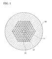
- FIG. 1 is a drawing showing an embodiment of a photonic band-gap fiber according to the present invention.
- a photonic band-gap fiber according to the present embodiment includes a first core 11 that has a refractive index of not higher than that of a clad 10, a second core that is disposed so as to surround the first core 11 and has a refractive index lower than that of the first core 11, a clad 10 that surrounds the second core 12, and large numbers of high refractive index portions 13 that are disposed in the clad in the vicinity of the second core 12.
- the high refractive index portions 13 have a higher refractive index than that of the clad 10 and show periodic insular arrangement forming a triangular lattice structure in a section.
- a propagation constant of the mode at a transmission wavelength is in the photonic band-gap determined by the periodic structure, and a propagation constant of a mode at a cutoff wavelength is outside the photonic band-gap.
- the photonic band-gap strengthens the confinement of the mode at the transmission wavelength.
- the photonic band-gap does not have an effect to enhance the confinement of the mode at a cutoff wavelength.
- the fiber of the basic structure shows large propagation loss at a transmission wavelength and at a cutoff wavelength.
- the periodic structure By adding the periodic structure, it is possible to selectively cause the transmission wavelength to propagate at a low propagation-loss.
- refractive indices of the first core 11 and the second core 12 are not more than the refractive index of the clad 10. Therefore, an operation-principle of the fiber is a wave-guiding by the photonic band-gap. Based on this principle, it is possible to avoid occurrence of a phenomena in that electric field of a mode propagating in the core is coupled with the mode propagating in the periodic structure, then the coupled mode propagates and subsequently be re-coupled with the mode propagating in the core.
- a photonic band-gap fiber of the present embodiment can achieve a high filtering effect with respect to a light that has a wavelength of which a propagation constant of a mode is outside the photonic band-gap fiber.
- the refractive index of the first core 11 and the second core 12 are not higher than that of the clad 10 in the photonic band-gap fiber according to the present embodiment, the refractive index of the first core 11 may be up to about 0.1 % higher than that of the clad.
- a core mode exist in the first core 11.
- the core mode has an effective refractive index of an intermediate value between the refractive index of the first core and the refractive index of the clad 10, and propagates in the core.
- the electric field of the core mode can be mutually coupled with an electric field of the mode of cutoff-wavelength propagating in the periodic structure portion, there is a possibility of an occurrence of the phenomena in that the electric filed once coupled to a mode propagates in the periodic structure from a core mode, is re-coupled to the core mode.
- the mode propagating in the periodic structure portion and allowing coupling with the core mode is weakly confined, it is possible to release the confinement of the mode propagating in the periodic structure portion even when an extremely large bending loss which cannot be avoided while using the photonic band-gap fiber is generated.
- section of the first core has a circular shape.
- a mode-field of the fiber has a substantially concentric circular shape.
- angle-dependence does not occur in the connection-loss.
- the fibers of the present invention can be connected to a conventional optical fiber having a concentric refractive index profile.
- the photonic band-gap fiber of the present invention has a solid structure free of air holes in the interior of the above-described periodic structure portion and the core. Therefore, when the fibers are connected to each other, or connected to the other type of optical fiber, hole collapse by heating (a phenomena that occurs under an existence of voids) does not occur, and the structure of the end-face of the fiber at the fusion spliced point does not change. Therefore, it is possible to perform fusion splicing of the fiber whole controlling the optical loss at a low level.
- the first core 11, the second core 12, the high refractive index portion 13, and the clad 10 are each made of silica glass. Therefore, it is possible to realize a low-loss fiber, and it is possible to fusion-bond the fiber to a silica glass optical fiber widely used in the present time.
- the photonic band-gap fiber of the present embodiment may be prepared by a method similar to the known method of producing a photonic band-gap fiber. An embodiment of the method is explained below.
- FIG. 1 indicates an embodiment in which two-layered silica glass rods are stacked to form five layers.
- the above-described packed body is placed in a vacuum heating furnace and the packed body as a whole is heated by a heater or the like.
- two ends of the packed body may be confined by installing caps. While evacuating the interior of the cylinder through the caps, an outer portion of the cylinder is heated by an oxygen-hydrogen frame. As a result, the silica glass is softened and fills in the interstices of the cylinder.
- the preform of the optical fiber having a structure shown in FIG. 1 is prepared.
- the thus obtained preform of an optical fiber is set in a known optical fiber-drawing apparatus (drawing apparatus), and is drawn in the same manner as in the production of general optical fibers, thereby obtaining the photonic band-gap fiber of FIG. 1 .
- draw apparatus drawing apparatus
- high refractive index glass rods having higher refractive index than the pure silica glass rods may be prepared and these rods may be packed one by one in the cylinder.
- a photonic band-gap fiber having a structure shown in 1 was produced.
- the clad 10 is made of pure silica glass having a refractive index of 1.45.
- the first core 11 having a diameter d1 of 17.8 ⁇ m and relative refractive index difference ⁇ 1 from the clad of 0 % is disposed in the clad.
- the second core 12 having a diameter d2 of 25 ⁇ m and relative refractive index difference ⁇ 2 from the clad 10 of -3.6 % exists around the first core 11.
- the high refractive index portions 13 each having a diameter dh of 5.6 ⁇ m and relative refractive index difference ⁇ h from the clad 10 of 1.6 % are arranged around the second core 12 so as to form a periodic structure of triangular lattice with a periodic interval of 14.0 ⁇ m.
- the triangular lattice lacks two layers from the centre so as to dispose the core, and forms five layered periodic structure.
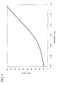
- FIG. 3 shows a dispersion curve of a mode guided (wave-guided) in the core of an optical fiber, where the fiber has a basic structure that lacks a periodic structure around the second core 12.
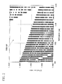
- a band diagram of the periodic structure is shown in FIG. 2 . In this map, the region showing no data points denotes the band-gap.
- confinement of the mode occurs by the effect of the photonic band-gap, where dispersion curve of the mode guided in the core is enclosed in the band-gap at the wavelength of the mode.
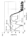
- FIG. 4 shows a result of superimposing the band diagram of the periodic structure on the dispersion curve of the mode guided in the core.
- the dispersion curve of the mode guided in the core exists in the band-gap where the wavelength is 1.0 ⁇ m to 1.1 ⁇ m.
- the dispersion curve of the core-mode is not present in the band-gap.
- the mode guided in the core at a wavelength of 1.0 ⁇ m to 1.1 ⁇ m is not confined by the periodic structure. Therefore, the photonic band-gap fiber of FIG. 1 can function as a wavelength filter.
- FIG. 5 shows the results of a calculation of mode-loss in a fiber of a basic structure, where the second core 12 is not surrounded by the periodic structure. Large loss occurs irrespective of the wavelength.
- FIG. 6 is the results of a calculation of mode-loss where the periodic structure shown in FIG. 1 is provided. As shown in FIG. 6 , mode-loss is very small in the band-gap, while the mode-loss is large at the ends of the band-gap, and outside the band-gap.
- the fiber according to the present invention has an effect of removing light, for example unnecessary ASE light or stimulated Raman scattering, having a wavelength different from that of signal light.
- light for example unnecessary ASE light or stimulated Raman scattering
- stimulated Raman scattering appears around the wavelength of 1.14 ⁇ m. Since the loss of the fundamental mode is 30dB/m or more at a wavelength of 1.14 ⁇ m, it is possible to suppress the stimulated Raman scattering effectively.
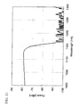
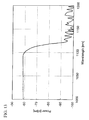
- a photonic band-gap fiber having a structure of FIG. 1 was produced. 1m length of fiber was pulled out, only the core portion was excited by the white light, and the transmission band was measured. The result is shown in FIG. 7 . Bending diameters varied from 180 mm ⁇ to 120 mm ⁇ . It can be understood that the light of a wavelength of 1.08 ⁇ m propagates but the light of a wavelength of 1.14 ⁇ m is attenuated by about 30dB where the bending diameter is between 180 mm ⁇ and 160 mm ⁇ . Therefore, this fiber can effectively suppress the generation of stimulated Raman scattering having a wavelength of 1.14 ⁇ m when the high power fiber laser was oscillated at a wavelength of 1.08 ⁇ m.
- transmission characteristics at a wavelength of 1.00 ⁇ m to 1.05 ⁇ m is largely changed by changing the bending diameter from 180 mm ⁇ to 120 mm ⁇ . This is caused by the bending resulting in leakage of the mode, as shown in FIG. 8 , propagating in the first core by coupling with the mode, as shown in FIG. 9 , mainly propagating in a portion between the second core and the periodic structure. Since the mode propagating in the portion between the second core and the periodic structure is weakly confined, the light is easily radiated to the clad by bending or the like, thereby causing propagation loss.
- By appropriately controlling the bending diameter of the fiber it is possible to dampen unnecessary light, such as ASE at a wavelength of 1.00 ⁇ m to 1.05 ⁇ m and parasitic oscillation, frequently causing problems in a fiber-laser.
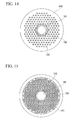
- a photonic band-gap fiber having a structure shown in FIG. 10 was produced.
- the clad 100 is made of pure silica glass having a refractive index of 1.45.
- the first core 101 having a diameter d1 of 12.0 ⁇ m and relative refractive index difference ⁇ 1 from the clad of 0 % is disposed in the clad 100.
- the second core 102 having a diameter d3 of 22.0 ⁇ m and relative refractive index difference ⁇ 2 from the clad 10 of -3.6 % exists around the first core 101.
- the high refractive index portions 103 each having a diameter dh of 3.6 ⁇ m and a relative refractive index difference ⁇ h from the clad 100 of 1.6 % are arranged around the second core 102 so as to form a periodic structure of triangle lattice with a periodic interval of 9.0 ⁇ m.
- the periodic structure lacks two layers from the center so as to dispose the core therein, and forms five layered periodic structure.
- This fiber was fusion-spliced to a conventional type fiber having a concentric distribution of refractive index and a similar mode-field diameter. As a result, it was possible to stably obtain a fusion-splicing loss of 0.1dB or less at a wavelength of 1.06 ⁇ m. Distribution of an electric field mainly depends on the shape of the first core. Since the first core of this fiber has a circular section, the electric field shows a concentric distribution. Therefore, it is possible to reduce connection loss caused by the difference in the shape of the mode field. Thus, in the photonic band-gap fiber of the present invention, it is possible to reduce connection loss with a conventional type fiber.
- a photonic band-gap fiber having a structure shown in FIG. 12 was produced.
- a clad glass rod 120 made of pure silica glass had a refractive index of 1.45.
- the first core 121 having a diameter d1 of 29.0 ⁇ m and a relative refractive index difference ⁇ 1 of 0.0% was disposed inside the clad 120.
- the second core 122 having a diameter d2 of 35.0 ⁇ m and a relative refractive index difference ⁇ 2 from the clad 10 of -3.6 % existed around the first core 121.
- the high refractive index portions 123 each having a diameter dh of 5.8 ⁇ m and a relative refractive index difference ⁇ h from the clad of 1.6 % were arranged around the second core 122 so as to form a periodic structure of a triangular lattice with a periodic interval of 14.5 ⁇ m.
- the triangular lattice lacked two layers from the center so as to dispose the core, and formed a five layered periodic structure.
- a photonic band-gap fiber having a structure shown in FIG. 14 was produced.
- a clad 140 was a glass rod made of pure silica glass having a refractive index of 1.45.
- a first core 141 having a diameter d1 of 28.6 ⁇ m and a relative refractive index difference ⁇ 1 from the clad 140 of 0.0% was disposed inside the clad 140.
- the second core 142 was disposed in the periphery of the first core 141.
- the second core had a relative refractive index difference ⁇ 2 from the clad 140 of -0.15%, and had d2 of 34.4 ⁇ m as a diameter of circle inscribing the clad surrounding the core.
- High refractive index portions 143 were disposed around the second core 142 so as to form a triangular lattice structure with a periodic interval of 8.1 ⁇ m, wherein each of the high refractive index portions 143 has a radius of 5.1 ⁇ m and a substantially parabolic shaped distribution of refractive index where a maximum value of the refractive index difference ⁇ h from the clad 140 was 2.8%.
- the periodic structure lacks three layers from the centre so as to dispose the core, and forms a five or six layered periodic structure.
- the outer diameter of the fiber was 215 ⁇ m.
- circumferential members constituting the periodic structure portion were disposed periodically in the tube constituting the clad 140, and a core member constituting the first core 140 and the second core 142 was disposed in the center. At that time, since the diameter of the core member was different from that of the circumferential member, interstitial spaces were formed between the core member and the circumferential members. If the drawing is performed under the presence of the interstitial spaces, undesirable deformation of the core or disorder of the periodic structure may occur during drawing to integrate the different members. Therefore, as shown in FIG. 15 , by further disposing an intermediate member 156 between the core member and the circumferential members, it is possible to inhibit the deformation of the core and disorder of the periodic structure.
- the refractive index of the intermediate member 156 is equal to or higher than the refractive index of the first core 141, it is sometimes undesirable since there is a possibility that mode coupling occurs between the mode guided in the core and the mode guided in the portion corresponding to the intermediate member, causing a loss of core mode in the transmission band formed by the effect of the photonic band gap.
- generation of unnecessary loss caused by mode coupling in the transmission band formed by the effect of the photonic band gap is inhibited by controlling the refractive index of the intermediate member 156 to be similar to a refractive index of the second core 142.
- the refractive index of the intermediate member 156 is not limited to the embodiment of the present example, and can be modified within a range lower than the refractive index of the first core 141.
- a 6 m length of fiber was extracted.
- a light from a pulse fiber laser for processing having a center weave-length of 1.08 ⁇ m, a peak power of 18kW, and an average power of 30W was guided by the fiber to a work to be processed.
- stimulated Raman scattering was not generated at a wavelength of 1.14 ⁇ m.
- High powered light outgone from the main body of the pulse fiber laser for processing could be guided stably to the work without suffering an influence of change in wavelength spectrum caused by stimulated Raman scattering.
- the relative refractive index difference ⁇ h of the high-index portion has a large value of at most 2.8%. Therefore, even when bending of a diameter of about 50 mm was made on the fiber for guiding the laser light to the work, reduction of transmission band caused by the bending loss was sufficiently decreased, and the light was stably guided to the work.
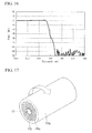
- FIG. 17 is a drawing showing the structure of a fiber of another example according to the present invention. While the structure of the cross section of the fiber of the present embodiment is similar to the fiber of Example 4, the fiber is constituted as an amplification fiber, wherein the first core 171 was doped with ytterbium, and a periphery of the clad 170a was covered by a second clad 170b composed of a fluororesin having a refractive index of 1.38.
- the first core 171 is doped with ytterbium, the first core has a relative index difference of 0.05% compared with pure silica.
- the fiber of a fused state was twisted.
- the high refractive index portions 173 were constituted to have a helical configuration, and substantially bent in the lengthwise direction. Therefore, the light propagating in the high refractive index portions generates loss such as macro-bent loss and micro-bent loss.
- the first core 171 is placed in the center of the fiber cross section, bending of the first core in the lengthwise direction does not occur.
- the refractive index of the first core 171 is slightly larger than that of the clad 170a.
- the fiber of the present example has substantially similar transmission property and cut-off property as those of Example 4. Therefore, when the fiber of the present example is used as a fiber for amplifying the laser light of 1.08 ⁇ m in wavelength, it is possible to suppress the first order stimulated Raman scattering at a wavelength of around 1.08 ⁇ m.
- the fiber of the present example can be used preferably as a double clad structured fiber for amplifier. If the fiber is not twisted, a problematic phenomenon occurs when the fiber is used as a double clad structure fiber for amplifier. That is, an pump light excited in the clad 170a is guided in the high refractive index portion 173 and is not used for amplifying the signal light, thereby decreasing the utilization ratio of exited light in the amplifier. However, if the photonic band-gap fiber of the present example is used, the pump light guided in the high refractive index portion 173 is radiated from the high refractive index portion 173 by losses such as macro-bend loss and micro-bend loss, absorbed by the core, and is reused in the amplification of the signal light. Therefore, when the photonic band-gap fiber of the present example is used in the double clad structured fiber for amplifier, it is possible to enhance the utilization ratio of pump light in the amplifier.
- the fiber of example 5 is subjected to substantially sine-wave shaped twisting having a period P of twist of 1 cm and a maximum angle A of twist of 20 ⁇ radian.
- the fiber is rotated 3 times by the twisting within the fiber length of 0.25 cm. It is very difficult to apply such a degree of twisting after a solidification of the fiber.
- the amount of absorption by the ytterbium doped in the core was 0.4dB/m.
- the pump light incident to the high refractive index portion 173 was radiated to the clad by bend loss and subsequently absorbed by ytterbium doped in the core. As a result, residual pump light in the high refractive index portion 173 was not observed.
- the fiber was used as a fiber for amplifying the laser light of 1.08 ⁇ m in wavelength, it was possible to suppress the first order stimulated Raman scattering of light of wavelength around 1.14 ⁇ m.
- Non-patent reference J.D. Love et al., Radiation from single-mode helical fibers, Electronics letters, vol. 23, No.21, pp 1109-1110, 1987 ) describes an optical loss in a fiber having a helical configuration of a core along its lengthwise direction, and can be used as a guide line to know the degree of twisting required for the loss of light leaked to high refractive index portion 173 in the photonic band-gap fiber of Example 4. Actually, the loss is different depending on the shape of the core, order of the mode, and radius of the helix.
- the non-patent reference shows that a twisting of about 1 rotation per 5 mm is required for obtaining a loss of 1dB/m or less within a range of refractive index distribution which can be realized by a general silica-based optical fiber. While the fiber is twisted in a single direction in the above non patent reference, even when the twisting has a sine-wave shape or other shapes, the light leaked to the high refractive index portion 173 suffers loss provided that at least one rotation per about 5 mm is applied to the fiber by the twisting. In addition, it is possible to increase the loss of light leaked to the high refractive index portion 173 in accordance with the increased degree of twisting.
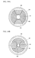
- a photonic band-gap fiber having a structure shown in FIG. 18A was produced.
- Clad 180 was made of pure silica glass having a refractive index of 1.45.
- the first core 181 having a diameter d1 of 28.6 ⁇ m and a relative refractive index difference ⁇ 1 from the clad 180 of 0.0% was disposed inside the clad 180.
- the second core had a relative refractive index difference ⁇ 2 from the clad 180 of -0.15% and d2 of 34.4 ⁇ m as the diameter of a circle inscribing the clad surrounding the core.
- a periodic structure was disposed in an arrangement of two-fold rotation symmetry around the second core 182.
- the periodic structure had low refractive index portions made of fluorine doped pure silica having a refractive index similar to the second core 182 and high refractive index portions 183 made of germanium doped pure silica.
- the fiber had an outer diameter of 215 ⁇ m.
- high refractive index portions 183 were disposed forming a triangular lattice structure with a periodic interval of 8.1 ⁇ m, wherein each of the high refractive index portions 183 had a radius of 5.1 ⁇ m and a substantially parabolic shaped distribution of refractive index where the maximum value of the refractive index difference ⁇ h from the clad was 2.8%.
- the periodic structure lacks three layers from the centre so as to dispose the core, and forms a five layered periodic structure.
- the periodic structure portion is made of pure silica doped with germanium and has a largely different thermal expansion coefficient from those of clad 180 made of pure silica and the low refractive index portion made of pure silica doped with fluorine. Therefore, if the cross section has a rotation symmetry of 2 fold or less as shown in FIG. 18A , birefringence is generated by thermal stress. Therefore, it is possible to make the fiber function as a polarization maintaining fiber without providing an additional stress-applying portion.
- the fiber When the birefringence of the fundamental mode of the thus produced fiber was measured, the fiber had a birefringence of 1 ⁇ 10 -4 or more at a wavelength of 1.08 ⁇ m and could function as a polarization maintaining fiber. In addition, the fiber also had a wavelength filtering effect due to the effect of the photonic band-gap.
- the first core 181 of the fiber of the present invention has a circular section. Since the distribution of the electric filed is mainly dominated by the shape of the first core 181, the electric field has a concentric distribution, mode birefringence is not generated, and only stress-originated birefringence is generated.
- a photonic band-gap fiber of the present invention is not limited to the present example.
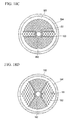
- Various configuration is allowed as shown in FIG. 18B , FIG. 18C, FIG. 18D provided that a high refractive index portion 183 that generates birefringence in the core by thermal stress is disposed at a rotational symmetry of 2 fold or less.
- silica glass doped with boron is used as a stress-applying member for forming a polarization maintaining fiber in the silica glass fiber. Therefore, it is possible to consider a configuration in which a stress applying portion 185 is additionally provided as shown in FIG. 18E . Since the refractive index of the fluorine doped pure silica is lower than that of the pure silica, it is necessary to provides the stress-applying portion separately from the high refractive index portion 183. Therefore, it is necessary to arrange the high refractive index portions 183 appropriately, thereby decreasing the degree of freedom of design. Further, in a structure as shown in FIG.
- the fiber of the present example has the same cross section as Example 4.
- the fiber is constituted of a fiber for amplification having double-clad structure, in which the first core is doped with ytterbium, and the periphery of the clad is covered by the second clad made of fluoric resin having a refractive index of 1.38.
- a long-period fiber grating is written on the high refractive index portion.
- the fiber is constituted such that the pump light guided in the high refractive index portion is partially radiated from the high refractive index portion when the pump light is introduced by the clad excitation.
- the fiber of the present example may be preferably used as a double-clad structured fiber for amplifier.
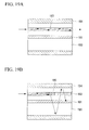
- the pump light guided in the high refractive index portion is radiated from the high refractive index portion 193 by the long period fiber grating, and is coupled with another guide mode guided by the difference in refractive index between the clad 190 and the second clad 194, and is subsequently absorbed by the core and used in amplification of the signal light. Therefore, by using the photonic band-gap fiber as a fiber having a double clad structure for amplifier, it is possible to enhance the utilization ratio of pump light in the amplifier. It is preferable that the guide mode guided in the high refractive index portion 193 has an effective refractive index which is smaller than the refractive index of the clad 190a and larger than the refractive index of the second clad 194.
- the guide mode since the effective refractive index is smaller than the clad 190, the guide mode is not confined in the high refractive index portion. In addition, since the effective refractive index is larger than the clad 194, the guide mode can propagate in the second clad 194. Therefore, it is possible to make the pump light reach the core effectively. More preferably, as shown in FIG. 19C , by making the guide mode to be coupled with the mode propagating in the core, it is possible to make the pump light reach the core more effectively.
- any fiber grating is acceptable provided that the fiber grating can radiate the pump light guided in the high refractive index portion 193 to the outside the high refractive index portion 193 and makes the light to be coupled with another guide mode.
- the fiber grating can radiate the light to a direction opposite the direction of the propagation direction of the pump light using a slanted fiber grating. In this case, it is possible to have the light be coupled with the mode that propagates in the core in the opposite direction, thereby making the pump light to reach the core effectively.
- an pump light is newly introduced in the clad at a potion where the pump light is radiated to the clad by the fiber grating. Therefore, by optimizing the lengthwise positions of fiber grating to be written, it is possible to optimize the lengthwise distribution of the pump light in the fiber used for signal amplification.
- the pump light radiated from the high refractive index portion propagates in the same direction as its propagation direction in the high refractive index portion. Therefore, for example, it is preferable to write the fiber grating in the positions to ensure a sufficient fiber length to sufficiently absorb the radiated pump light by the core.
- the pump light radiated from the high refractive index portion propagates in the reverse direction with respect to the propagation direction of the light in the high refractive index portion.
- pump light is partially introduced from the end surface opposite to the incident surface of the pump light, thereby homogenizing the lengthwise distribution of the pump light in the amplifier. Therefore, the case is preferable.
- the photonic band-gap fiber of the present invention By providing a periodic structure around the first, and the second core, it is possible to make the photonic band-gap fiber of the present invention to function as a wavelength filter. As a result, it is possible to decrease the propagation loss of transmission wavelength and increase the propagation loss of cutoff wavelength, thereby obtaining a high wavelength filtering effect at the cutoff wavelength.
Landscapes
- Physics & Mathematics (AREA)
- General Physics & Mathematics (AREA)
- Optics & Photonics (AREA)
- Lasers (AREA)
- Light Guides In General And Applications Therefor (AREA)
- Glass Compositions (AREA)
- Optical Fibers, Optical Fiber Cores, And Optical Fiber Bundles (AREA)
Applications Claiming Priority (3)
| Application Number | Priority Date | Filing Date | Title |
|---|---|---|---|
| JP2007054273 | 2007-03-05 | ||
| JP2007149180 | 2007-06-05 | ||
| PCT/JP2008/053515 WO2008108269A1 (fr) | 2007-03-05 | 2008-02-28 | Fibre à bande interdite photonique |
Publications (2)
| Publication Number | Publication Date |
|---|---|
| EP2090910A1 true EP2090910A1 (fr) | 2009-08-19 |
| EP2090910A4 EP2090910A4 (fr) | 2011-05-11 |
Family
ID=39738152
Family Applications (1)
| Application Number | Title | Priority Date | Filing Date |
|---|---|---|---|
| EP08712086A Withdrawn EP2090910A4 (fr) | 2007-03-05 | 2008-02-28 | Fibre à bande interdite photonique |
Country Status (4)
| Country | Link |
|---|---|
| US (1) | US8031999B2 (fr) |
| EP (1) | EP2090910A4 (fr) |
| JP (1) | JP4452756B2 (fr) |
| WO (1) | WO2008108269A1 (fr) |
Families Citing this family (19)
| Publication number | Priority date | Publication date | Assignee | Title |
|---|---|---|---|---|
| JP2008283175A (ja) * | 2007-04-10 | 2008-11-20 | Fujikura Ltd | ファイバレーザ装置 |
| JP4998357B2 (ja) * | 2007-04-13 | 2012-08-15 | 住友電気工業株式会社 | フォトニックバンドギャップ光ファイバ、光伝送システム及びそのシステムにおける誘導ラマン散乱抑制方法 |
| JP2009076493A (ja) * | 2007-09-18 | 2009-04-09 | Sumitomo Electric Ind Ltd | 増幅用光ファイバ |
| US8406594B2 (en) * | 2008-08-18 | 2013-03-26 | Nkt Photonics A/S | Optical fiber with resonant structure of cladding features connected to light sink |
| US9347271B2 (en) * | 2008-10-17 | 2016-05-24 | Foro Energy, Inc. | Optical fiber cable for transmission of high power laser energy over great distances |
| JP4588113B2 (ja) * | 2008-11-05 | 2010-11-24 | 株式会社フジクラ | フォトニックバンドギャップファイバ |
| DE102009060711A1 (de) * | 2009-03-13 | 2010-10-07 | Fraunhofer-Gesellschaft zur Förderung der angewandten Forschung e.V. | Einzelmodenpropagation in mikrostrukturierten Fasern |
| JP2011039497A (ja) * | 2009-07-17 | 2011-02-24 | Sumitomo Electric Ind Ltd | フォトニック結晶ファイバ |
| CN101852889B (zh) * | 2010-05-17 | 2012-12-19 | 哈尔滨工程大学 | 一种变周期型阵列多芯光纤及其制备方法 |
| US8995494B1 (en) * | 2011-04-29 | 2015-03-31 | Bae Systems Information And Electronic Systems Integration Inc. | Multi-band laser architecture |
| EP2717095A4 (fr) * | 2011-06-03 | 2015-04-15 | Sumitomo Electric Industries | Dispositif de source de lumière et procédé de traitement |
| CN103033883A (zh) * | 2013-01-04 | 2013-04-10 | 北京遥测技术研究所 | 长周期光栅加工方法及长周期光栅 |
| FR3007536B1 (fr) * | 2013-06-24 | 2015-07-17 | Lyon Ecole Centrale | Composant optique a fibre |
| JP2016148749A (ja) * | 2015-02-12 | 2016-08-18 | 株式会社フジクラ | 分散シフト光ファイバ |
| DE202015009023U1 (de) * | 2015-06-19 | 2016-07-18 | Laser- Und Medizin- Technologie Gmbh | Lateral abstrahlende Lichtwellenleiter |
| CN112285060A (zh) * | 2020-10-23 | 2021-01-29 | 天津理工大学 | 双芯微结构光纤模间干涉型高灵敏度折射率传感器 |
| WO2025028627A1 (fr) * | 2023-08-02 | 2025-02-06 | 株式会社フジクラ | Fibre de maintien de polarisation |
| CN121605331A (zh) * | 2023-08-02 | 2026-03-03 | 株式会社藤仓 | 保偏光纤 |
| WO2025213144A1 (fr) * | 2024-04-05 | 2025-10-09 | Ofs Fitel, Llc | Réduction de l'asymétrie de viscosité axiale pour réduire les distorsions géométriques pendant l'étirage de fibres optiques |
Family Cites Families (22)
| Publication number | Priority date | Publication date | Assignee | Title |
|---|---|---|---|---|
| JPH01147412A (ja) | 1987-12-03 | 1989-06-09 | Furukawa Electric Co Ltd:The | シングルモード光フアイバ |
| JP3072842B2 (ja) * | 1998-05-07 | 2000-08-07 | 日本電信電話株式会社 | 単一モード光ファイバ |
| US6404966B1 (en) | 1998-05-07 | 2002-06-11 | Nippon Telegraph And Telephone Corporation | Optical fiber |
| WO2000042458A1 (fr) | 1999-01-18 | 2000-07-20 | Sumitomo Electric Industries, Ltd. | Fibre optique et son procede de fabrication |
| JP4293156B2 (ja) | 1999-04-13 | 2009-07-08 | 住友電気工業株式会社 | 光ファイバ及びそれを含む光通信システム |
| JP4080164B2 (ja) | 1999-04-13 | 2008-04-23 | 住友電気工業株式会社 | 光ファイバ及びそれを含む光通信システム |
| US6788865B2 (en) * | 2000-03-03 | 2004-09-07 | Nippon Telegraph And Telephone Corporation | Polarization maintaining optical fiber with improved polarization maintaining property |
| JP2002237637A (ja) * | 2001-02-08 | 2002-08-23 | Toshiba Corp | ファイバレーザ装置 |
| CN1275057C (zh) | 2001-04-11 | 2006-09-13 | 晶体纤维公司 | 具有特殊色散特性的双芯光子晶体光纤(pcf) |
| JP3865208B2 (ja) | 2001-08-31 | 2007-01-10 | 日本電信電話株式会社 | フォトニック結晶構造光ファイバ |
| JP3630664B2 (ja) | 2002-01-29 | 2005-03-16 | 三菱電線工業株式会社 | 偏波保持フォトニッククリスタルファイバ |
| JP3628299B2 (ja) * | 2002-02-05 | 2005-03-09 | 三菱電線工業株式会社 | ダブルクラッドファイバ及びダブルクラッドファイバの製造方法 |
| JP2005025056A (ja) * | 2003-07-04 | 2005-01-27 | Nippon Telegr & Teleph Corp <Ntt> | フォトニック結晶ファイバ |
| JP2006011328A (ja) * | 2004-06-29 | 2006-01-12 | Nippon Telegr & Teleph Corp <Ntt> | フォトニック結晶ファイバ |
| JP4444177B2 (ja) * | 2004-08-11 | 2010-03-31 | 古河電気工業株式会社 | 光ファイバ、光ファイバテープおよび光インターコネクションシステム |
| US7190869B2 (en) * | 2004-10-29 | 2007-03-13 | The Hong Kong Polytechnic University | Two-mode photonic crystal fiber and applications thereof |
| US7212717B2 (en) | 2004-11-01 | 2007-05-01 | Sumitomo Electric Industries, Ltd. | Optical fiber |
| JP2006126725A (ja) * | 2004-11-01 | 2006-05-18 | Sumitomo Electric Ind Ltd | 光ファイバ |
| JP2006139018A (ja) * | 2004-11-11 | 2006-06-01 | Sumitomo Electric Ind Ltd | 光ファイバ |
| US7272287B2 (en) | 2005-05-11 | 2007-09-18 | Fitel Usa Corp | Optical fiber filter for suppression of amplified spontaneous emission |
| JP4547317B2 (ja) | 2005-08-24 | 2010-09-22 | 竹田 佳与 | 敷布団 |
| JP2007149180A (ja) | 2005-11-25 | 2007-06-14 | Hitachi Ltd | 光ディスク装置 |
-
2008
- 2008-02-28 JP JP2008541531A patent/JP4452756B2/ja not_active Expired - Fee Related
- 2008-02-28 WO PCT/JP2008/053515 patent/WO2008108269A1/fr not_active Ceased
- 2008-02-28 EP EP08712086A patent/EP2090910A4/fr not_active Withdrawn
-
2009
- 2009-09-04 US US12/554,576 patent/US8031999B2/en active Active
Also Published As
| Publication number | Publication date |
|---|---|
| US20090324186A1 (en) | 2009-12-31 |
| EP2090910A4 (fr) | 2011-05-11 |
| US8031999B2 (en) | 2011-10-04 |
| JP4452756B2 (ja) | 2010-04-21 |
| JPWO2008108269A1 (ja) | 2010-06-17 |
| WO2008108269A1 (fr) | 2008-09-12 |
Similar Documents
| Publication | Publication Date | Title |
|---|---|---|
| US8031999B2 (en) | Photonic band-gap fiber | |
| US6990282B2 (en) | Photonic crystal fibers | |
| US8406594B2 (en) | Optical fiber with resonant structure of cladding features connected to light sink | |
| EP3397999B1 (fr) | Systèmes utilisant fibres optiques à mélange de modes | |
| US8660396B2 (en) | Multi-cladding optical fiber, optical fiber module, fiber laser, and fiber amplifier | |
| EP2082462B1 (fr) | Fibre a bande interdite photonique et amplificateur a fibre | |
| US10838141B2 (en) | Spun round core fiber | |
| JP5679420B2 (ja) | ソリッドフォトニックバンドギャップファイバおよび該ファイバを用いたファイバモジュールおよびファイバアンプ、ファイバレーザ | |
| EP3025175B1 (fr) | Amplification de gainage à large mode simple dans des fibres actives à double gainage | |
| WO2008053922A1 (fr) | Fibre à bande interdite photonique | |
| US7978947B2 (en) | Photonic bandgap fiber | |
| US20100254669A1 (en) | Photonic bandgap fiber | |
| US20140003778A1 (en) | Hollow core fiber with improvements relating to optical properties and its use, method of its production and use thereof | |
| CN101622560A (zh) | 光子带隙光纤 | |
| JP2007316526A (ja) | フォトニックバンドギャップファイバ及びファイバレーザ | |
| JP6430832B2 (ja) | 光ビームの強度の横方向空間プロファイルを、好ましくは微細構造光ファイバを用いて変換する装置 | |
| US20090181842A1 (en) | Polarization-maintaining optical fiber and method for manufacturing the same | |
| JP3640943B2 (ja) | フォトニッククリスタルファイバ |
Legal Events
| Date | Code | Title | Description |
|---|---|---|---|
| PUAI | Public reference made under article 153(3) epc to a published international application that has entered the european phase |
Free format text: ORIGINAL CODE: 0009012 |
|
| 17P | Request for examination filed |
Effective date: 20090605 |
|
| AK | Designated contracting states |
Kind code of ref document: A1 Designated state(s): AT BE BG CH CY CZ DE DK EE ES FI FR GB GR HR HU IE IS IT LI LT LU LV MC MT NL NO PL PT RO SE SI SK TR |
|
| DAX | Request for extension of the european patent (deleted) | ||
| A4 | Supplementary search report drawn up and despatched |
Effective date: 20110412 |
|
| RIC1 | Information provided on ipc code assigned before grant |
Ipc: G02B 6/00 20060101AFI20080925BHEP Ipc: G02B 6/036 20060101ALI20110406BHEP Ipc: H01S 3/067 20060101ALN20110406BHEP |
|
| 17Q | First examination report despatched |
Effective date: 20120323 |
|
| GRAP | Despatch of communication of intention to grant a patent |
Free format text: ORIGINAL CODE: EPIDOSNIGR1 |
|
| RIC1 | Information provided on ipc code assigned before grant |
Ipc: H01S 3/067 20060101ALN20160404BHEP Ipc: G02B 6/02 20060101ALI20160404BHEP Ipc: G02B 6/00 20060101AFI20160404BHEP Ipc: G02B 6/036 20060101ALN20160404BHEP Ipc: G02B 6/024 20060101ALN20160404BHEP |
|
| INTG | Intention to grant announced |
Effective date: 20160421 |
|
| RIC1 | Information provided on ipc code assigned before grant |
Ipc: G02B 6/036 20060101ALN20160412BHEP Ipc: G02B 6/02 20060101ALI20160412BHEP Ipc: G02B 6/00 20060101AFI20160412BHEP Ipc: G02B 6/024 20060101ALN20160412BHEP Ipc: H01S 3/067 20060101ALN20160412BHEP |
|
| INTG | Intention to grant announced |
Effective date: 20160429 |
|
| INTG | Intention to grant announced |
Effective date: 20160509 |
|
| STAA | Information on the status of an ep patent application or granted ep patent |
Free format text: STATUS: THE APPLICATION IS DEEMED TO BE WITHDRAWN |
|
| 18D | Application deemed to be withdrawn |
Effective date: 20160920 |