EP2090920A1 - Dispositif de représentation optique, notamment objectif, doté d'au moins un écran système - Google Patents
Dispositif de représentation optique, notamment objectif, doté d'au moins un écran système Download PDFInfo
- Publication number
- EP2090920A1 EP2090920A1 EP09160725A EP09160725A EP2090920A1 EP 2090920 A1 EP2090920 A1 EP 2090920A1 EP 09160725 A EP09160725 A EP 09160725A EP 09160725 A EP09160725 A EP 09160725A EP 2090920 A1 EP2090920 A1 EP 2090920A1
- Authority
- EP
- European Patent Office
- Prior art keywords
- diaphragm
- lamellae
- bottoms
- movable
- objective according
- Prior art date
- Legal status (The legal status is an assumption and is not a legal conclusion. Google has not performed a legal analysis and makes no representation as to the accuracy of the status listed.)
- Granted
Links
- 238000012634 optical imaging Methods 0.000 title description 7
- 241000446313 Lamella Species 0.000 claims abstract description 4
- 230000003287 optical effect Effects 0.000 claims description 18
- 239000004065 semiconductor Substances 0.000 claims description 5
- 230000005855 radiation Effects 0.000 abstract 1
- 210000000554 iris Anatomy 0.000 description 27
- 238000003384 imaging method Methods 0.000 description 13
- 230000008901 benefit Effects 0.000 description 6
- 230000008859 change Effects 0.000 description 6
- 238000004519 manufacturing process Methods 0.000 description 4
- 238000005096 rolling process Methods 0.000 description 4
- XUIMIQQOPSSXEZ-UHFFFAOYSA-N Silicon Chemical compound [Si] XUIMIQQOPSSXEZ-UHFFFAOYSA-N 0.000 description 3
- 230000000694 effects Effects 0.000 description 3
- 230000002349 favourable effect Effects 0.000 description 3
- 229910052710 silicon Inorganic materials 0.000 description 3
- 239000010703 silicon Substances 0.000 description 3
- 238000010276 construction Methods 0.000 description 2
- 230000006872 improvement Effects 0.000 description 2
- 239000002184 metal Substances 0.000 description 2
- 238000000034 method Methods 0.000 description 2
- 238000005457 optimization Methods 0.000 description 2
- 238000003860 storage Methods 0.000 description 2
- 206010052128 Glare Diseases 0.000 description 1
- 230000001154 acute effect Effects 0.000 description 1
- 230000004075 alteration Effects 0.000 description 1
- 238000000576 coating method Methods 0.000 description 1
- 230000008878 coupling Effects 0.000 description 1
- 238000010168 coupling process Methods 0.000 description 1
- 238000005859 coupling reaction Methods 0.000 description 1
- 230000001419 dependent effect Effects 0.000 description 1
- 238000010586 diagram Methods 0.000 description 1
- 238000005530 etching Methods 0.000 description 1
- 230000007257 malfunction Effects 0.000 description 1
- 230000036316 preload Effects 0.000 description 1
- 230000008569 process Effects 0.000 description 1
Images

Classifications
-
- G—PHYSICS
- G03—PHOTOGRAPHY; CINEMATOGRAPHY; ANALOGOUS TECHNIQUES USING WAVES OTHER THAN OPTICAL WAVES; ELECTROGRAPHY; HOLOGRAPHY
- G03F—PHOTOMECHANICAL PRODUCTION OF TEXTURED OR PATTERNED SURFACES, e.g. FOR PRINTING, FOR PROCESSING OF SEMICONDUCTOR DEVICES; MATERIALS THEREFOR; ORIGINALS THEREFOR; APPARATUS SPECIALLY ADAPTED THEREFOR
- G03F7/00—Photomechanical, e.g. photolithographic, production of textured or patterned surfaces, e.g. printing surfaces; Materials therefor, e.g. comprising photoresists; Apparatus specially adapted therefor
- G03F7/70—Microphotolithographic exposure; Apparatus therefor
- G03F7/70216—Mask projection systems
- G03F7/7025—Size or form of projection system aperture, e.g. aperture stops, diaphragms or pupil obscuration; Control thereof
-
- G—PHYSICS
- G02—OPTICS
- G02B—OPTICAL ELEMENTS, SYSTEMS OR APPARATUS
- G02B5/00—Optical elements other than lenses
- G02B5/005—Diaphragms
Definitions
- the invention relates to an optical imaging device, in particular objective, with at least one system shutter, wherein an opening of the system shutter is adjustable in its opening diameter.
- irises which have at least four - but usually more - thin slats, which are generally sickle-shaped and rotatably mounted at one end in a fixed version.
- the other end is provided with a pin as a guide device which is inserted in a groove or backdrop of a rotatable ring so that by rotating the rotatable ring, the slats are moved in such a way that the remaining opening diameter of the diaphragm can be varied ,
- optical-mechanical devices in particular the system apertures in an imaging device
- optical properties such. to improve the telecentricity error or other aberrations of the imaging device.
- this object is achieved in that the position of the opening of the system panel is determined as a function of the opening diameter of the system panel.
- the imaging devices are used to image miniaturized templates for a chip layout in a miniaturized form which are mechanically just to be produced on a silicon wafer coated with a photosensitive layer.
- various etching processes which passes through the silicon wafer, are from the Thus, microstructures then exposed the circuits of the computer chip or of the semiconductor component.
- Smallest deviations and distortions in the image of the chip layout template on the silicon wafer caused by the imaging device can already lead to line contacts, short circuits or other electronic malfunctions in the microstructures of the finished computer chip. Therefore bring even in the production of computer chips and semiconductor devices used imaging devices even the smallest quality gains great advantages, which is why the optical advantages of adjustable in their axial position system aperture come into full effect here.
- the change in the axial position of the system shutter is achieved as a function of its opening diameter in a structurally comparatively simple construction.
- the system diaphragm has at least two diaphragms which are arranged at an axial distance from one another, wherein a respective other diaphragm is optically active as a function of the aperture diameter of the system diaphragm.
- Optically active here means that the optically active diaphragm or its optically active edge provides for the lateral limitation of the beam of rays in the imaging device.
- This double or multiple diaphragm according to the invention offers the advantage that the effect according to the invention can be achieved here without complex mechanics for adjusting the axial position.
- the at least two diaphragms are arranged such that they lie in at least two planes which are axially different from the optical axis of the system diaphragm.
- Critical is the range when two of the panels "overtake”, so if at a certain opening diameter of the system aperture briefly the optically effective edges of two of the panels are optically active at the same time. To avoid blur effects, this requires a very precise mechanics, such as the storage of the panels or their individual parts by means of play-free preloaded roller bearing elements.
- the system shutter on slats which are arranged between two rotatable relative to each movable diaphragm bottoms, wherein at least one of the diaphragm plates is rotatably movable and wherein the unit of the blades and the two diaphragm plates in the axial direction is movable.
- This inventive solution variant of the task comes with only a single aperture.
- the advantage here is that all axial intermediate planes are available. Depending on the aperture diameter of the diaphragm, this can namely change its axial position, since the unit of fins and relatively movable diaphragm bottoms is coupled by mechanical guide elements in such a way that the desired adjustment of the axial position of the aperture can be achieved depending on the opening diameter.
- This structural design has the particular advantage that a guide groove, which coordinates the rotational and the axial movements of the two diaphragm floors to each other, can be designed in any geometric shape. Depending on the shape of the guide groove, various mathematical dependencies between the rotational movement and thus the change in the opening diameter and the axial movement of the system aperture can be realized.
- the diaphragm is likewise formed by means of lamellae, wherein the lamellae and the surfaces of the diaphragm plates facing the lamellae extend over at least approximately the greatest part of the aperture diameter of the system diaphragm at an angle to the optical axis of the system aperture are arranged.
- the optically effective edge of the diaphragm can, depending on the geometric shape of the slats or the surfaces of the diaphragm bottoms facing the slats, be fixed to e.g. a conical surface or on the lateral surface of a Kugelkalottenform be moved.
- the fins arranged rotationally symmetrically with respect to the optical axis of the system aperture move, e.g. when closing the system shutter, then in a linear or semicircular relationship between the opening diameter and the axial position in the light path of the imaging device.
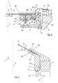
- Fig. 1 a cross-section through a system panel 1 is shown, wherein the system panel 1 has two individual panels 2a, 2b and irises 2a, 2b. These iris diaphragms 2 a, 2 b are constructed from lamellae 3, which are arranged at least approximately perpendicular to the optical axis 4 of the system diaphragm 1.
- the system panel 1 is mounted in a socket 5, wherein the socket 5 fixed to a shell of a lens in the version 5 is firmly connected to a sheath of an objective (not shown).
- the system shutter 1 may have in addition to the two individual apertures 2a, 2b still another aperture.
- this additional diaphragm may be a fixed diaphragm or a fixed disc which is mounted in the system diaphragm 1 at an axial distance from the two iris diaphragms 2a, 2b.
- the lamellae 3 of the two panels 2a, 2b lie with their respective opening diameter D a , D b facing away between two mutually relatively movable cover plates 6a, 6b, 6c.
- the lamellae 3 are supported by play-free preloaded bearing devices 7 in each case one of the cooperating with them aperture plates 6b, 6c.
- each of the slats 3 has a guide device 8.
- the guide devices 8 are guided in a gate 9a, 9b incorporated into the respective cover plate 6a, 6b, whereby a backlash-free pretensioning of the guide devices 8 with respect to the slide 9a, 9b is also to be provided here.
- the backlash-free preload of the bearing or guide means 7 or 8 may be e.g. be formed so that each of the lamellae 3 is biased by torsion springs (not shown) in such a way that they play in the bearing device 7, e.g. a rolling bearing, and the respective gate 9a, 9b is added.
- the lamellae 3 supported by the bearing devices 7 are moved on a track predetermined for the respective lamella 3 by the guide devices 8 running in the differently configured linkages 9a, 9b.
- Optically effective edges 10a, 10b of the lamellae 3 thereby change their opening diameter D a , D b .
- the scenes 9a, 9b of the irises 2a, 2b are designed in the manner that the opening of the system panel 1 or each of the iris diaphragms 2 a, 2 b can be enlarged or reduced in the manner of an approximately circular polygon.
- the system panel 1 has a third fixed diaphragm (not shown)
- the case may still occur that neither of the two irises 2a and 2b is optically active, but only those at an axial distance from the iris diaphragms 2a, 2b arranged fixed aperture.
- a ring gear 11 constructed from a plurality of individual elements 12, 13, 14 is mounted with a roller bearing 15 in the socket 5 and the individual elements 12, 13, 14 of the ring gear 11 are interconnected by a plurality of fastening elements 16.
- one of the individual elements 12 of the ring gear 11 has a toothing 17 and can be offset by a pinion 18 in a rotational to the optical axis 4 of the system shutter 1 movement.
- a drive unit 19, in this case an electric motor 19, serves to rotate the pinion 18 and thus the ring gear 11 and the shutter plates 6a, 6c connected to it about the optical axis 4 of the system shutter 1.
- the drive unit 19 is firmly connected to the socket 5.
- the diaphragm base 6b located between the two irises 2a, 2b is likewise fixed to the holder 5 by means of a fastening element 20.
- one of the individual elements 14 of Tellerrads 11 performed by one or more recesses 21 in the lying between the two irises 2a, 2b diaphragm bottom 6b.
- By another fastening element 22 of the diaphragm bottom 6a is attached to the single element 14 of the ring gear 11.
- Fig. 2 a further embodiment of the system aperture can be seen.
- the lamellae 3 of the iris diaphragm 2 are arranged between two diaphragm bottoms 6a, 6b or groove ring 6a and diaphragm bottom 6b.
- the storage devices 7 and the guide means 8 and the gate 9 also exist here, but only once per slat 3.
- the other elements in Fig. 2 are in principle the in Fig. 1 explained in construction and operation comparable.
- the iris diaphragm 2 forms together with the Nutenring 6a and the diaphragm bottom 6b, an inner ring 23, an outer ring 24 and a rolling bearing 25, a structural unit 26.
- the assembly 26 of the diaphragm bottom 6b is connected to the inner ring 23
- the Nutenring 6a is connected to the outer ring 24 connected.
- the inner ring 23 is designed to be rotatable relative to the outer ring 24, wherein between the inner ring 23 and the outer ring 24, the roller bearing 25 is arranged.
- a relative movement of the two diaphragm bottoms 6a, 6b to each other thus also means that there is a relative movement of the inner ring 23 relative to the outer ring 24.
- the outer ring 24 and thus also a diaphragm base 6a is held against rotation by retaining elements 27 against the version 5.
- the holding elements 27 may be e.g. be formed as sheet metal tabs 27 which are attached to the socket 5 via fasteners 28.
- the metal tabs 27 then come to rest between two projections 29 which allow axial movement of the outer ring 24, but prevent twisting.
- three to six retaining elements 27 are distributed over the circumference of the system panel 1.
- the ring gear 11 has one or more driving pins 30, which may be evenly distributed over the circumference of the system panel 1.
- the driving pins 30 engage in each case a recess 31 in the inner ring 23, so that transmits a generated by the drive means 19 rotational movement of the ring gear 11 on the inner ring 23 and thus on the shutter bottom 6b.
- the driving pins 30 are in the respective recesses 31 by rolling elements 32 stored in the way that a low-friction and largely backlash-free axial relative movement of the inner ring 23 to the driving pin 30 and thus also to the ring gear 11 is possible.
- connection of the driving pin 30 and the inner ring 23, a spring element 33 which is designed in such a way that it holds the assembly 26 in an axial center position, so that the axial movement of the assembly 26 relative to the ring gear 11 in both directions with comparatively small forces is possible.
- the ring gear 11 has a guide pin 34 fixedly connected to it.
- the tip of the guide pin 33 is provided with a roller bearing 35, which runs in a guide groove 36 in the outer ring 24.
- the guide groove 36 and the roller bearing 35 of the guide pin 34 thereby form the mechanical coupling of the rotational movement of the ring gear 11 with the axial movement of the assembly 26th
- the optically effective edge 10 of the iris diaphragm 2 can be moved on an approximately arbitrary curve.
- the dependence between the opening diameter D and the axial position of the optical effective edge 10 of the system panel 1 in the manufacturing possibilities for the guide groove 36 and according to the given optical requirements selectable, both optically and manufacturing generally generally only continuous curves makes sense are.
- Fig. 3 shows a schematic diagram of another embodiment of the system panel 1.
- an aperture bottom 6a is firmly connected to the outer frame 5.
- the other diaphragm base 6b is mounted on the roller bearing 15 in the version 5.
- a part of the diaphragm bottom 6b simultaneously represents the ring gear 11 and can be rotationally moved via the drive unit 19 with the pinion 18.
- the lamellae 3 of the iris diaphragm 2 are moved over the bearing devices 7, guide devices 8 and links 9 (not shown here) already described in the preceding figures.
- the peculiarity of this embodiment lies in the fact that the lamellae 3 of the diaphragm 2 are arranged in such a manner that each one is arranged at an acute angle to the optical axis of the system diaphragm 1.
- the optically effective edges 10 of the lamellae 3 and the iris diaphragm 2 then moves on the lateral surface, e.g. a cone or a paraboloid of revolution.
- the axial position of the optically active edge 10 of the iris diaphragm 2 can be predetermined here as a function of its opening diameter D.
- both the slats 3 and the slats 3 facing surfaces 37 of the diaphragm bottoms 6a, 6b in the form formed the desired lateral surface.
- the lateral surface should always be the lateral surface of a rotationally symmetrical body relative to the optical axis 4 of the system diaphragm 1.
- the optically effective edges 10 of the lamellae 3 then move on this respective surface.
Landscapes
- Physics & Mathematics (AREA)
- General Physics & Mathematics (AREA)
- Optics & Photonics (AREA)
- Diaphragms For Cameras (AREA)
- Lens Barrels (AREA)
- Mechanical Light Control Or Optical Switches (AREA)
Applications Claiming Priority (2)
| Application Number | Priority Date | Filing Date | Title |
|---|---|---|---|
| DE19955984A DE19955984A1 (de) | 1999-11-20 | 1999-11-20 | Optische Abbildungsvorrichtung, insbesondere Objektiv mit wenigstens einer Systemblende |
| EP00122003A EP1102103B1 (fr) | 1999-11-20 | 2000-10-10 | Dispositif optique, en particulier objectif, avec au moins un diaphragme |
Related Parent Applications (2)
| Application Number | Title | Priority Date | Filing Date |
|---|---|---|---|
| EP00122003.7 Division | 2000-10-10 | ||
| EP00122003A Division EP1102103B1 (fr) | 1999-11-20 | 2000-10-10 | Dispositif optique, en particulier objectif, avec au moins un diaphragme |
Publications (2)
| Publication Number | Publication Date |
|---|---|
| EP2090920A1 true EP2090920A1 (fr) | 2009-08-19 |
| EP2090920B1 EP2090920B1 (fr) | 2011-04-13 |
Family
ID=7929810
Family Applications (2)
| Application Number | Title | Priority Date | Filing Date |
|---|---|---|---|
| EP00122003A Expired - Lifetime EP1102103B1 (fr) | 1999-11-20 | 2000-10-10 | Dispositif optique, en particulier objectif, avec au moins un diaphragme |
| EP09160725A Expired - Lifetime EP2090920B1 (fr) | 1999-11-20 | 2000-10-10 | Dispositif de représentation optique, notamment objectif, doté d'au moins un écran système |
Family Applications Before (1)
| Application Number | Title | Priority Date | Filing Date |
|---|---|---|---|
| EP00122003A Expired - Lifetime EP1102103B1 (fr) | 1999-11-20 | 2000-10-10 | Dispositif optique, en particulier objectif, avec au moins un diaphragme |
Country Status (6)
| Country | Link |
|---|---|
| US (1) | US6445510B1 (fr) |
| EP (2) | EP1102103B1 (fr) |
| JP (1) | JP5107486B2 (fr) |
| KR (1) | KR100807445B1 (fr) |
| DE (3) | DE19955984A1 (fr) |
| TW (1) | TW460707B (fr) |
Families Citing this family (14)
| Publication number | Priority date | Publication date | Assignee | Title |
|---|---|---|---|---|
| US8009343B2 (en) * | 2003-08-01 | 2011-08-30 | Carl Zeiss Smt Gmbh | Optical imaging device having at least one system diaphragm |
| KR101281445B1 (ko) | 2003-10-29 | 2013-07-02 | 칼 짜이스 에스엠테 게엠베하 | 조리개 변경 장치 |
| KR101109844B1 (ko) | 2003-12-02 | 2012-04-06 | 칼 짜이스 에스엠티 게엠베하 | 프로젝션 광학 시스템 |
| US7301707B2 (en) * | 2004-09-03 | 2007-11-27 | Carl Zeiss Smt Ag | Projection optical system and method |
| JP2008527403A (ja) * | 2004-12-30 | 2008-07-24 | カール・ツァイス・エスエムティー・アーゲー | 投影光学系 |
| US7310131B2 (en) * | 2005-08-02 | 2007-12-18 | Asml Netherlands B.V. | Lithographic apparatus and device manufacturing method |
| WO2007020004A1 (fr) | 2005-08-17 | 2007-02-22 | Carl Zeiss Smt Ag | Objectif de projection et procede pour optimiser un obturateur de systeme d'un objectif de projection |
| JP4003790B2 (ja) | 2005-08-23 | 2007-11-07 | セイコーエプソン株式会社 | 光学絞り装置、およびプロジェクタ |
| DE102006038455A1 (de) | 2006-08-16 | 2008-02-21 | Carl Zeiss Smt Ag | Optisches System für die Halbleiterlithographie |
| JP6041304B2 (ja) | 2009-03-27 | 2016-12-07 | カール・ツァイス・エスエムティー・ゲーエムベーハー | Euvマイクロリソグラフィ用の照明光学系、この種の照明光学系用のeuv減衰器、及びこの種の照明光学系を有する照明系及び投影露光装置 |
| DE102010005449B4 (de) * | 2010-01-24 | 2015-07-23 | Leica Camera Ag | Blendenlamelle mit Tragvorrichtung |
| DE102012111731B4 (de) * | 2012-12-03 | 2017-10-12 | Carl Zeiss Industrielle Messtechnik Gmbh | Irisblende und optische Vorrichtung |
| DE102014223811B4 (de) | 2014-11-21 | 2016-09-29 | Carl Zeiss Smt Gmbh | Abbildende Optik für die EUV-Projektionslithographie, Projektionsbelichtungsanlage und Verfahren zur Herstellung eines strukturierten Bauteils |
| JP7204400B2 (ja) * | 2018-09-28 | 2023-01-16 | キヤノン株式会社 | 露光装置及び物品の製造方法 |
Citations (2)
| Publication number | Priority date | Publication date | Assignee | Title |
|---|---|---|---|---|
| US4525037A (en) * | 1982-07-09 | 1985-06-25 | Minolta Camera Kabushiki Kaisha | Objective lens assembly of variable focal length having a diaphragm mechanism with adjustable aperture |
| JPH11195607A (ja) * | 1997-10-07 | 1999-07-21 | Nikon Corp | 投影露光装置、該装置を用いた半導体デバイスの製造方法、及び露光方法 |
Family Cites Families (15)
| Publication number | Priority date | Publication date | Assignee | Title |
|---|---|---|---|---|
| JPS5760009Y2 (fr) | 1974-08-17 | 1982-12-21 | ||
| US4149775A (en) | 1977-08-03 | 1979-04-17 | Blake Daniel H | Zoom lens apparatus with adjustable aperture |
| US4904055A (en) | 1988-10-03 | 1990-02-27 | Eastman Kodak Company | Variable aperture formed by linearly movable elements |
| JPH0477743A (ja) * | 1990-07-19 | 1992-03-11 | Canon Inc | 投影露光装置 |
| JPH0553170A (ja) * | 1991-08-29 | 1993-03-05 | Canon Inc | 絞り装置を有する光学機器 |
| JPH0623017U (ja) * | 1992-08-24 | 1994-03-25 | オリンパス光学工業株式会社 | 視野絞り機構 |
| JPH07199272A (ja) * | 1993-12-29 | 1995-08-04 | Minolta Co Ltd | カメラレンズの絞り補正機構 |
| JPH07301845A (ja) * | 1994-05-06 | 1995-11-14 | Canon Inc | 絞り装置及びそれを用いた投影露光装置 |
| DE4417489A1 (de) | 1994-05-19 | 1995-11-23 | Zeiss Carl Fa | Höchstaperturiges katadioptrisches Reduktionsobjektiv für die Miktrolithographie |
| JP3530241B2 (ja) * | 1994-12-21 | 2004-05-24 | 日本電産コパル株式会社 | カメラ用シャッタ |
| JPH08220591A (ja) * | 1995-02-10 | 1996-08-30 | Nikon Corp | 絞り移動装置 |
| JP3597311B2 (ja) * | 1996-07-18 | 2004-12-08 | オリンパス株式会社 | 光ピックアップ |
| JP3925576B2 (ja) * | 1997-07-24 | 2007-06-06 | 株式会社ニコン | 投影光学系、該光学系を備えた露光装置、及び該装置を用いたデバイスの製造方法 |
| JP2000075185A (ja) * | 1998-08-31 | 2000-03-14 | Nikon Corp | レンズ鏡筒 |
| TW367050U (en) * | 1999-01-14 | 1999-08-11 | Umax Data Systems Inc | Improved bladed aperture stop of a lens |
-
1999
- 1999-11-20 DE DE19955984A patent/DE19955984A1/de not_active Withdrawn
-
2000
- 2000-10-04 US US09/678,715 patent/US6445510B1/en not_active Expired - Lifetime
- 2000-10-10 EP EP00122003A patent/EP1102103B1/fr not_active Expired - Lifetime
- 2000-10-10 EP EP09160725A patent/EP2090920B1/fr not_active Expired - Lifetime
- 2000-10-10 DE DE50016095T patent/DE50016095D1/de not_active Expired - Lifetime
- 2000-10-10 DE DE50015730T patent/DE50015730D1/de not_active Expired - Lifetime
- 2000-10-18 KR KR1020000061164A patent/KR100807445B1/ko not_active Expired - Fee Related
- 2000-10-24 JP JP2000324184A patent/JP5107486B2/ja not_active Expired - Fee Related
- 2000-11-16 TW TW089124245A patent/TW460707B/zh not_active IP Right Cessation
Patent Citations (2)
| Publication number | Priority date | Publication date | Assignee | Title |
|---|---|---|---|---|
| US4525037A (en) * | 1982-07-09 | 1985-06-25 | Minolta Camera Kabushiki Kaisha | Objective lens assembly of variable focal length having a diaphragm mechanism with adjustable aperture |
| JPH11195607A (ja) * | 1997-10-07 | 1999-07-21 | Nikon Corp | 投影露光装置、該装置を用いた半導体デバイスの製造方法、及び露光方法 |
Also Published As
| Publication number | Publication date |
|---|---|
| US6445510B1 (en) | 2002-09-03 |
| DE19955984A1 (de) | 2001-05-23 |
| EP1102103A3 (fr) | 2001-08-08 |
| KR100807445B1 (ko) | 2008-02-25 |
| EP1102103B1 (fr) | 2009-08-26 |
| DE50015730D1 (de) | 2009-10-08 |
| JP5107486B2 (ja) | 2012-12-26 |
| KR20010051088A (ko) | 2001-06-25 |
| DE50016095D1 (de) | 2011-05-26 |
| EP1102103A2 (fr) | 2001-05-23 |
| TW460707B (en) | 2001-10-21 |
| JP2001154235A (ja) | 2001-06-08 |
| EP2090920B1 (fr) | 2011-04-13 |
Similar Documents
| Publication | Publication Date | Title |
|---|---|---|
| EP2090920B1 (fr) | Dispositif de représentation optique, notamment objectif, doté d'au moins un écran système | |
| WO2003093902A2 (fr) | Systeme d'eclairage notamment destine a la lithographie en ultraviolet extreme | |
| DE102009054888A1 (de) | Optisches Element mit einer Mehrzahl von refletiven Facettenelementen | |
| EP3616993A1 (fr) | Dispositif de réglage pour un phare de véhicule automobile | |
| DE69630341T2 (de) | Vorrichtung zur Erzeugung einer oszillierenden Bewegung einer Linse in einem Objektiv mit automatischer Fokuseinstellung. | |
| DE102008026979B3 (de) | Vorrichtung zum Korrigieren von Abbildungsfehlern in einem optischen System | |
| DE4004010C2 (de) | Objektiv mit einer Blende zur Vermeidung von Streulicht und störenden Reflexen | |
| DE10309859A1 (de) | Winkeleinstellvorrichtung | |
| DE4013743A1 (de) | Optischer abstandsschalter | |
| DE102014114465B3 (de) | Mikroskop mit objektivabhängiger Begrenzung des Drehwinkels des Zoomdrehrades | |
| DE102018207410A1 (de) | Facettenspiegel für eine Beleuchtungsoptik für die Projektionslithographie | |
| WO2015135966A1 (fr) | Composant optique | |
| DE2346398C3 (de) | Verstellbare Einrichtung für Linsensysteme | |
| DE29916641U1 (de) | Transversales Zoom-Objektiv | |
| DE102022132106B4 (de) | Einstellschlitten | |
| DE3112828A1 (de) | "zoomobjektiv" | |
| DE102013213254A1 (de) | Betätigungseinheit für ein optisches element mit zweidimensionalem stellantrieb | |
| DE2720541B2 (de) | Justiereinrichtung für die örtliche Lage des Spiegels bei einer einäugigen Spiegelreflexkamera | |
| DE102013106562A1 (de) | Verstelleinrichtung für einen Kraftfahrzeugscheinwerfer | |
| DE2040227A1 (de) | Fotografisches Objektiv | |
| DE2042229A1 (de) | Lichtstrahlablenkvorrichtung | |
| DE102015213619A1 (de) | Spiegelfacettenanordnung | |
| DE10132119A1 (de) | Motorische Blende für optische Baugruppen | |
| DE4326260C1 (de) | Steuerbare Horizontblende für Planetarien | |
| AT256613B (de) | Objektivblende für photographische Kameras |
Legal Events
| Date | Code | Title | Description |
|---|---|---|---|
| PUAI | Public reference made under article 153(3) epc to a published international application that has entered the european phase |
Free format text: ORIGINAL CODE: 0009012 |
|
| 17P | Request for examination filed |
Effective date: 20090520 |
|
| AC | Divisional application: reference to earlier application |
Ref document number: 1102103 Country of ref document: EP Kind code of ref document: P |
|
| AK | Designated contracting states |
Kind code of ref document: A1 Designated state(s): CH DE FR GB LI NL |
|
| RIN1 | Information on inventor provided before grant (corrected) |
Inventor name: MAUL, GUENTER Inventor name: GELLRICH, BERNHARD Inventor name: SCHUSTER, KARLHEINZ Inventor name: BISCHOFF, THOMAS Inventor name: TRUNZ, MICHAEL Inventor name: MUEHLBEYER, MICHAEL |
|
| 17Q | First examination report despatched |
Effective date: 20091102 |
|
| GRAP | Despatch of communication of intention to grant a patent |
Free format text: ORIGINAL CODE: EPIDOSNIGR1 |
|
| RIN1 | Information on inventor provided before grant (corrected) |
Inventor name: GELLRICH, BERNHARD Inventor name: MAUL, GUENTER Inventor name: TRUNZ, MICHAEL Inventor name: SCHUSTER, KARLHEINZ Inventor name: MUEHLBEYER, MICHAEL Inventor name: BISCHOFF, THOMAS |
|
| GRAS | Grant fee paid |
Free format text: ORIGINAL CODE: EPIDOSNIGR3 |
|
| RAP1 | Party data changed (applicant data changed or rights of an application transferred) |
Owner name: CARL ZEISS SMT GMBH |
|
| GRAA | (expected) grant |
Free format text: ORIGINAL CODE: 0009210 |
|
| AC | Divisional application: reference to earlier application |
Ref document number: 1102103 Country of ref document: EP Kind code of ref document: P |
|
| AK | Designated contracting states |
Kind code of ref document: B1 Designated state(s): CH DE FR GB LI NL |
|
| REG | Reference to a national code |
Ref country code: GB Ref legal event code: FG4D Free format text: NOT ENGLISH |
|
| REG | Reference to a national code |
Ref country code: CH Ref legal event code: EP |
|
| REF | Corresponds to: |
Ref document number: 50016095 Country of ref document: DE Date of ref document: 20110526 Kind code of ref document: P |
|
| REG | Reference to a national code |
Ref country code: DE Ref legal event code: R096 Ref document number: 50016095 Country of ref document: DE Effective date: 20110526 |
|
| REG | Reference to a national code |
Ref country code: NL Ref legal event code: T3 |
|
| PLBE | No opposition filed within time limit |
Free format text: ORIGINAL CODE: 0009261 |
|
| STAA | Information on the status of an ep patent application or granted ep patent |
Free format text: STATUS: NO OPPOSITION FILED WITHIN TIME LIMIT |
|
| 26N | No opposition filed |
Effective date: 20120116 |
|
| REG | Reference to a national code |
Ref country code: DE Ref legal event code: R097 Ref document number: 50016095 Country of ref document: DE Effective date: 20120116 |
|
| REG | Reference to a national code |
Ref country code: CH Ref legal event code: PL |
|
| GBPC | Gb: european patent ceased through non-payment of renewal fee |
Effective date: 20111010 |
|
| REG | Reference to a national code |
Ref country code: FR Ref legal event code: ST Effective date: 20120629 |
|
| PG25 | Lapsed in a contracting state [announced via postgrant information from national office to epo] |
Ref country code: LI Free format text: LAPSE BECAUSE OF NON-PAYMENT OF DUE FEES Effective date: 20111031 Ref country code: CH Free format text: LAPSE BECAUSE OF NON-PAYMENT OF DUE FEES Effective date: 20111031 |
|
| PG25 | Lapsed in a contracting state [announced via postgrant information from national office to epo] |
Ref country code: GB Free format text: LAPSE BECAUSE OF NON-PAYMENT OF DUE FEES Effective date: 20111010 Ref country code: FR Free format text: LAPSE BECAUSE OF NON-PAYMENT OF DUE FEES Effective date: 20111102 |
|
| PGFP | Annual fee paid to national office [announced via postgrant information from national office to epo] |
Ref country code: DE Payment date: 20141022 Year of fee payment: 15 |
|
| PGFP | Annual fee paid to national office [announced via postgrant information from national office to epo] |
Ref country code: NL Payment date: 20141021 Year of fee payment: 15 |
|
| REG | Reference to a national code |
Ref country code: DE Ref legal event code: R119 Ref document number: 50016095 Country of ref document: DE |
|
| REG | Reference to a national code |
Ref country code: NL Ref legal event code: MM Effective date: 20151101 |
|
| PG25 | Lapsed in a contracting state [announced via postgrant information from national office to epo] |
Ref country code: DE Free format text: LAPSE BECAUSE OF NON-PAYMENT OF DUE FEES Effective date: 20160503 |
|
| PG25 | Lapsed in a contracting state [announced via postgrant information from national office to epo] |
Ref country code: NL Free format text: LAPSE BECAUSE OF NON-PAYMENT OF DUE FEES Effective date: 20151101 |