EP2090922A1 - Gespanntes optisches Element mit Crimprahmen und -feder - Google Patents
Gespanntes optisches Element mit Crimprahmen und -feder Download PDFInfo
- Publication number
- EP2090922A1 EP2090922A1 EP09152718A EP09152718A EP2090922A1 EP 2090922 A1 EP2090922 A1 EP 2090922A1 EP 09152718 A EP09152718 A EP 09152718A EP 09152718 A EP09152718 A EP 09152718A EP 2090922 A1 EP2090922 A1 EP 2090922A1
- Authority
- EP
- European Patent Office
- Prior art keywords
- film
- optical
- diffuser
- optical element
- light
- Prior art date
- Legal status (The legal status is an assumption and is not a legal conclusion. Google has not performed a legal analysis and makes no representation as to the accuracy of the status listed.)
- Withdrawn
Links
- 230000003287 optical effect Effects 0.000 title claims abstract description 100
- 238000002788 crimping Methods 0.000 title claims abstract description 43
- 239000010408 film Substances 0.000 claims abstract description 222
- 239000012788 optical film Substances 0.000 claims abstract description 44
- 230000007246 mechanism Effects 0.000 claims abstract description 20
- 239000002245 particle Substances 0.000 claims description 41
- 238000000149 argon plasma sintering Methods 0.000 claims description 4
- -1 for example Substances 0.000 description 88
- 229920001577 copolymer Polymers 0.000 description 28
- 238000009792 diffusion process Methods 0.000 description 23
- 239000000463 material Substances 0.000 description 23
- 229920000642 polymer Polymers 0.000 description 22
- 239000011347 resin Substances 0.000 description 18
- 229920005989 resin Polymers 0.000 description 18
- 239000000203 mixture Substances 0.000 description 16
- 239000011159 matrix material Substances 0.000 description 13
- 229920000139 polyethylene terephthalate Polymers 0.000 description 13
- 239000005020 polyethylene terephthalate Substances 0.000 description 13
- PPBRXRYQALVLMV-UHFFFAOYSA-N Styrene Natural products C=CC1=CC=CC=C1 PPBRXRYQALVLMV-UHFFFAOYSA-N 0.000 description 12
- LYCAIKOWRPUZTN-UHFFFAOYSA-N Ethylene glycol Chemical compound OCCO LYCAIKOWRPUZTN-UHFFFAOYSA-N 0.000 description 11
- 229920003229 poly(methyl methacrylate) Polymers 0.000 description 9
- 230000002829 reductive effect Effects 0.000 description 9
- 238000012360 testing method Methods 0.000 description 9
- GWEVSGVZZGPLCZ-UHFFFAOYSA-N Titan oxide Chemical compound O=[Ti]=O GWEVSGVZZGPLCZ-UHFFFAOYSA-N 0.000 description 8
- IISBACLAFKSPIT-UHFFFAOYSA-N bisphenol A Chemical compound C=1C=C(O)C=CC=1C(C)(C)C1=CC=C(O)C=C1 IISBACLAFKSPIT-UHFFFAOYSA-N 0.000 description 8
- 239000004973 liquid crystal related substance Substances 0.000 description 8
- 238000004519 manufacturing process Methods 0.000 description 8
- 239000004926 polymethyl methacrylate Substances 0.000 description 8
- 239000011324 bead Substances 0.000 description 7
- 230000007613 environmental effect Effects 0.000 description 7
- 239000008188 pellet Substances 0.000 description 7
- VTYYLEPIZMXCLO-UHFFFAOYSA-L Calcium carbonate Chemical compound [Ca+2].[O-]C([O-])=O VTYYLEPIZMXCLO-UHFFFAOYSA-L 0.000 description 6
- KKEYFWRCBNTPAC-UHFFFAOYSA-N Terephthalic acid Chemical compound OC(=O)C1=CC=C(C(O)=O)C=C1 KKEYFWRCBNTPAC-UHFFFAOYSA-N 0.000 description 6
- 230000000977 initiatory effect Effects 0.000 description 6
- 229920002223 polystyrene Polymers 0.000 description 6
- 239000011800 void material Substances 0.000 description 6
- 229920001634 Copolyester Polymers 0.000 description 5
- 239000004793 Polystyrene Substances 0.000 description 5
- 230000005540 biological transmission Effects 0.000 description 5
- 238000013461 design Methods 0.000 description 5
- 238000000034 method Methods 0.000 description 5
- 230000010287 polarization Effects 0.000 description 5
- 229920000515 polycarbonate Polymers 0.000 description 5
- 239000004417 polycarbonate Substances 0.000 description 5
- 229920000728 polyester Polymers 0.000 description 5
- 239000000758 substrate Substances 0.000 description 5
- XKZQKPRCPNGNFR-UHFFFAOYSA-N 2-(3-hydroxyphenyl)phenol Chemical compound OC1=CC=CC(C=2C(=CC=CC=2)O)=C1 XKZQKPRCPNGNFR-UHFFFAOYSA-N 0.000 description 4
- 239000004743 Polypropylene Substances 0.000 description 4
- VYPSYNLAJGMNEJ-UHFFFAOYSA-N Silicium dioxide Chemical compound O=[Si]=O VYPSYNLAJGMNEJ-UHFFFAOYSA-N 0.000 description 4
- MCMNRKCIXSYSNV-UHFFFAOYSA-N Zirconium dioxide Chemical compound O=[Zr]=O MCMNRKCIXSYSNV-UHFFFAOYSA-N 0.000 description 4
- 239000002253 acid Substances 0.000 description 4
- TZCXTZWJZNENPQ-UHFFFAOYSA-L barium sulfate Chemical compound [Ba+2].[O-]S([O-])(=O)=O TZCXTZWJZNENPQ-UHFFFAOYSA-L 0.000 description 4
- 238000005286 illumination Methods 0.000 description 4
- QQVIHTHCMHWDBS-UHFFFAOYSA-N isophthalic acid Chemical compound OC(=O)C1=CC=CC(C(O)=O)=C1 QQVIHTHCMHWDBS-UHFFFAOYSA-N 0.000 description 4
- 238000011068 loading method Methods 0.000 description 4
- 229920001155 polypropylene Polymers 0.000 description 4
- 230000008569 process Effects 0.000 description 4
- BVKZGUZCCUSVTD-UHFFFAOYSA-L Carbonate Chemical compound [O-]C([O-])=O BVKZGUZCCUSVTD-UHFFFAOYSA-L 0.000 description 3
- MUBZPKHOEPUJKR-UHFFFAOYSA-N Oxalic acid Chemical compound OC(=O)C(O)=O MUBZPKHOEPUJKR-UHFFFAOYSA-N 0.000 description 3
- YIMQCDZDWXUDCA-UHFFFAOYSA-N [4-(hydroxymethyl)cyclohexyl]methanol Chemical compound OCC1CCC(CO)CC1 YIMQCDZDWXUDCA-UHFFFAOYSA-N 0.000 description 3
- 150000007513 acids Chemical class 0.000 description 3
- 239000000654 additive Substances 0.000 description 3
- 230000008901 benefit Effects 0.000 description 3
- 229940106691 bisphenol a Drugs 0.000 description 3
- 229910000019 calcium carbonate Inorganic materials 0.000 description 3
- 238000013329 compounding Methods 0.000 description 3
- MTHSVFCYNBDYFN-UHFFFAOYSA-N diethylene glycol Chemical compound OCCOCCO MTHSVFCYNBDYFN-UHFFFAOYSA-N 0.000 description 3
- 150000002148 esters Chemical class 0.000 description 3
- 239000010419 fine particle Substances 0.000 description 3
- 150000002334 glycols Chemical class 0.000 description 3
- 239000010954 inorganic particle Substances 0.000 description 3
- 229920003023 plastic Polymers 0.000 description 3
- 239000004033 plastic Substances 0.000 description 3
- 230000001902 propagating effect Effects 0.000 description 3
- 239000000126 substance Substances 0.000 description 3
- PXGZQGDTEZPERC-UHFFFAOYSA-N 1,4-cyclohexanedicarboxylic acid Chemical compound OC(=O)C1CCC(C(O)=O)CC1 PXGZQGDTEZPERC-UHFFFAOYSA-N 0.000 description 2
- KLZUFWVZNOTSEM-UHFFFAOYSA-K Aluminium flouride Chemical compound F[Al](F)F KLZUFWVZNOTSEM-UHFFFAOYSA-K 0.000 description 2
- 229920008347 Cellulose acetate propionate Polymers 0.000 description 2
- QIGBRXMKCJKVMJ-UHFFFAOYSA-N Hydroquinone Chemical compound OC1=CC=C(O)C=C1 QIGBRXMKCJKVMJ-UHFFFAOYSA-N 0.000 description 2
- OFOBLEOULBTSOW-UHFFFAOYSA-N Malonic acid Chemical compound OC(=O)CC(O)=O OFOBLEOULBTSOW-UHFFFAOYSA-N 0.000 description 2
- 229920001890 Novodur Polymers 0.000 description 2
- YGYAWVDWMABLBF-UHFFFAOYSA-N Phosgene Chemical compound ClC(Cl)=O YGYAWVDWMABLBF-UHFFFAOYSA-N 0.000 description 2
- 239000004698 Polyethylene Substances 0.000 description 2
- 238000010521 absorption reaction Methods 0.000 description 2
- 239000000853 adhesive Substances 0.000 description 2
- 230000001070 adhesive effect Effects 0.000 description 2
- WNLRTRBMVRJNCN-UHFFFAOYSA-N adipic acid Chemical compound OC(=O)CCCCC(O)=O WNLRTRBMVRJNCN-UHFFFAOYSA-N 0.000 description 2
- WERYXYBDKMZEQL-UHFFFAOYSA-N butane-1,4-diol Chemical compound OCCCCO WERYXYBDKMZEQL-UHFFFAOYSA-N 0.000 description 2
- 229920002301 cellulose acetate Polymers 0.000 description 2
- 229920006217 cellulose acetate butyrate Polymers 0.000 description 2
- 230000008859 change Effects 0.000 description 2
- 238000006243 chemical reaction Methods 0.000 description 2
- 230000003247 decreasing effect Effects 0.000 description 2
- 239000002274 desiccant Substances 0.000 description 2
- FLKPEMZONWLCSK-UHFFFAOYSA-N diethyl phthalate Chemical compound CCOC(=O)C1=CC=CC=C1C(=O)OCC FLKPEMZONWLCSK-UHFFFAOYSA-N 0.000 description 2
- ROORDVPLFPIABK-UHFFFAOYSA-N diphenyl carbonate Chemical compound C=1C=CC=CC=1OC(=O)OC1=CC=CC=C1 ROORDVPLFPIABK-UHFFFAOYSA-N 0.000 description 2
- 239000006185 dispersion Substances 0.000 description 2
- GHLKSLMMWAKNBM-UHFFFAOYSA-N dodecane-1,12-diol Chemical compound OCCCCCCCCCCCCO GHLKSLMMWAKNBM-UHFFFAOYSA-N 0.000 description 2
- 230000000694 effects Effects 0.000 description 2
- 238000001125 extrusion Methods 0.000 description 2
- 239000011521 glass Substances 0.000 description 2
- 238000001746 injection moulding Methods 0.000 description 2
- 229910010272 inorganic material Inorganic materials 0.000 description 2
- 238000009434 installation Methods 0.000 description 2
- 238000009413 insulation Methods 0.000 description 2
- 125000005395 methacrylic acid group Chemical group 0.000 description 2
- 239000011325 microbead Substances 0.000 description 2
- RXOHFPCZGPKIRD-UHFFFAOYSA-N naphthalene-2,6-dicarboxylic acid Chemical compound C1=C(C(O)=O)C=CC2=CC(C(=O)O)=CC=C21 RXOHFPCZGPKIRD-UHFFFAOYSA-N 0.000 description 2
- BDJRBEYXGGNYIS-UHFFFAOYSA-N nonanedioic acid Chemical compound OC(=O)CCCCCCCC(O)=O BDJRBEYXGGNYIS-UHFFFAOYSA-N 0.000 description 2
- XNGIFLGASWRNHJ-UHFFFAOYSA-N phthalic acid Chemical compound OC(=O)C1=CC=CC=C1C(O)=O XNGIFLGASWRNHJ-UHFFFAOYSA-N 0.000 description 2
- WLJVNTCWHIRURA-UHFFFAOYSA-N pimelic acid Chemical compound OC(=O)CCCCCC(O)=O WLJVNTCWHIRURA-UHFFFAOYSA-N 0.000 description 2
- 229920005668 polycarbonate resin Polymers 0.000 description 2
- 239000004431 polycarbonate resin Substances 0.000 description 2
- 229920001225 polyester resin Polymers 0.000 description 2
- 239000004645 polyester resin Substances 0.000 description 2
- 229920000573 polyethylene Polymers 0.000 description 2
- 239000002243 precursor Substances 0.000 description 2
- 238000012545 processing Methods 0.000 description 2
- CXMXRPHRNRROMY-UHFFFAOYSA-N sebacic acid Chemical compound OC(=O)CCCCCCCCC(O)=O CXMXRPHRNRROMY-UHFFFAOYSA-N 0.000 description 2
- 229920006126 semicrystalline polymer Polymers 0.000 description 2
- 239000000377 silicon dioxide Substances 0.000 description 2
- 239000000243 solution Substances 0.000 description 2
- TYFQFVWCELRYAO-UHFFFAOYSA-N suberic acid Chemical compound OC(=O)CCCCCCC(O)=O TYFQFVWCELRYAO-UHFFFAOYSA-N 0.000 description 2
- 239000004408 titanium dioxide Substances 0.000 description 2
- 229920002554 vinyl polymer Polymers 0.000 description 2
- PUPZLCDOIYMWBV-UHFFFAOYSA-N (+/-)-1,3-Butanediol Chemical compound CC(O)CCO PUPZLCDOIYMWBV-UHFFFAOYSA-N 0.000 description 1
- IDTODQQHHXCCBI-UHFFFAOYSA-N (4-methylphenyl) phenyl carbonate Chemical compound C1=CC(C)=CC=C1OC(=O)OC1=CC=CC=C1 IDTODQQHHXCCBI-UHFFFAOYSA-N 0.000 description 1
- HCNHNBLSNVSJTJ-UHFFFAOYSA-N 1,1-Bis(4-hydroxyphenyl)ethane Chemical compound C=1C=C(O)C=CC=1C(C)C1=CC=C(O)C=C1 HCNHNBLSNVSJTJ-UHFFFAOYSA-N 0.000 description 1
- YAXWOADCWUUUNX-UHFFFAOYSA-N 1,2,2,3-tetramethylpiperidine Chemical compound CC1CCCN(C)C1(C)C YAXWOADCWUUUNX-UHFFFAOYSA-N 0.000 description 1
- ALVZNPYWJMLXKV-UHFFFAOYSA-N 1,9-Nonanediol Chemical compound OCCCCCCCCCO ALVZNPYWJMLXKV-UHFFFAOYSA-N 0.000 description 1
- RTBFRGCFXZNCOE-UHFFFAOYSA-N 1-methylsulfonylpiperidin-4-one Chemical compound CS(=O)(=O)N1CCC(=O)CC1 RTBFRGCFXZNCOE-UHFFFAOYSA-N 0.000 description 1
- FQXGHZNSUOHCLO-UHFFFAOYSA-N 2,2,4,4-tetramethyl-1,3-cyclobutanediol Chemical compound CC1(C)C(O)C(C)(C)C1O FQXGHZNSUOHCLO-UHFFFAOYSA-N 0.000 description 1
- RKMGAJGJIURJSJ-UHFFFAOYSA-N 2,2,6,6-Tetramethylpiperidine Substances CC1(C)CCCC(C)(C)N1 RKMGAJGJIURJSJ-UHFFFAOYSA-N 0.000 description 1
- JLZIIHMTTRXXIN-UHFFFAOYSA-N 2-(2-hydroxy-4-methoxybenzoyl)benzoic acid Chemical compound OC1=CC(OC)=CC=C1C(=O)C1=CC=CC=C1C(O)=O JLZIIHMTTRXXIN-UHFFFAOYSA-N 0.000 description 1
- YMTYZTXUZLQUSF-UHFFFAOYSA-N 3,3'-Dimethylbisphenol A Chemical compound C1=C(O)C(C)=CC(C(C)(C)C=2C=C(C)C(O)=CC=2)=C1 YMTYZTXUZLQUSF-UHFFFAOYSA-N 0.000 description 1
- WTKWFNIIIXNTDO-UHFFFAOYSA-N 3-isocyanato-5-methyl-2-(trifluoromethyl)furan Chemical compound CC1=CC(N=C=O)=C(C(F)(F)F)O1 WTKWFNIIIXNTDO-UHFFFAOYSA-N 0.000 description 1
- JLBJTVDPSNHSKJ-UHFFFAOYSA-N 4-Methylstyrene Chemical compound CC1=CC=C(C=C)C=C1 JLBJTVDPSNHSKJ-UHFFFAOYSA-N 0.000 description 1
- SBBQDUFLZGOASY-OWOJBTEDSA-N 4-[(e)-2-(4-carboxyphenyl)ethenyl]benzoic acid Chemical compound C1=CC(C(=O)O)=CC=C1\C=C\C1=CC=C(C(O)=O)C=C1 SBBQDUFLZGOASY-OWOJBTEDSA-N 0.000 description 1
- SWZOQAGVRGQLDV-UHFFFAOYSA-N 4-[2-(4-hydroxy-2,2,6,6-tetramethylpiperidin-1-yl)ethoxy]-4-oxobutanoic acid Chemical compound CC1(C)CC(O)CC(C)(C)N1CCOC(=O)CCC(O)=O SWZOQAGVRGQLDV-UHFFFAOYSA-N 0.000 description 1
- ODJUOZPKKHIEOZ-UHFFFAOYSA-N 4-[2-(4-hydroxy-3,5-dimethylphenyl)propan-2-yl]-2,6-dimethylphenol Chemical compound CC1=C(O)C(C)=CC(C(C)(C)C=2C=C(C)C(O)=C(C)C=2)=C1 ODJUOZPKKHIEOZ-UHFFFAOYSA-N 0.000 description 1
- 125000004203 4-hydroxyphenyl group Chemical group [H]OC1=C([H])C([H])=C(*)C([H])=C1[H] 0.000 description 1
- NIXOWILDQLNWCW-UHFFFAOYSA-M Acrylate Chemical compound [O-]C(=O)C=C NIXOWILDQLNWCW-UHFFFAOYSA-M 0.000 description 1
- 239000005995 Aluminium silicate Substances 0.000 description 1
- SDDLEVPIDBLVHC-UHFFFAOYSA-N Bisphenol Z Chemical compound C1=CC(O)=CC=C1C1(C=2C=CC(O)=CC=2)CCCCC1 SDDLEVPIDBLVHC-UHFFFAOYSA-N 0.000 description 1
- DQEFEBPAPFSJLV-UHFFFAOYSA-N Cellulose propionate Chemical compound CCC(=O)OCC1OC(OC(=O)CC)C(OC(=O)CC)C(OC(=O)CC)C1OC1C(OC(=O)CC)C(OC(=O)CC)C(OC(=O)CC)C(COC(=O)CC)O1 DQEFEBPAPFSJLV-UHFFFAOYSA-N 0.000 description 1
- 239000001856 Ethyl cellulose Substances 0.000 description 1
- ZZSNKZQZMQGXPY-UHFFFAOYSA-N Ethyl cellulose Chemical compound CCOCC1OC(OC)C(OCC)C(OCC)C1OC1C(O)C(O)C(OC)C(CO)O1 ZZSNKZQZMQGXPY-UHFFFAOYSA-N 0.000 description 1
- CERQOIWHTDAKMF-UHFFFAOYSA-M Methacrylate Chemical compound CC(=C)C([O-])=O CERQOIWHTDAKMF-UHFFFAOYSA-M 0.000 description 1
- 239000000020 Nitrocellulose Substances 0.000 description 1
- ALQSHHUCVQOPAS-UHFFFAOYSA-N Pentane-1,5-diol Chemical compound OCCCCCO ALQSHHUCVQOPAS-UHFFFAOYSA-N 0.000 description 1
- 229920002319 Poly(methyl acrylate) Polymers 0.000 description 1
- 239000004952 Polyamide Substances 0.000 description 1
- 239000004695 Polyether sulfone Substances 0.000 description 1
- 239000004697 Polyetherimide Substances 0.000 description 1
- 229920002367 Polyisobutene Polymers 0.000 description 1
- KDYFGRWQOYBRFD-UHFFFAOYSA-N Succinic acid Natural products OC(=O)CCC(O)=O KDYFGRWQOYBRFD-UHFFFAOYSA-N 0.000 description 1
- 229920010524 Syndiotactic polystyrene Polymers 0.000 description 1
- 229910004366 ThF4 Inorganic materials 0.000 description 1
- FJWGYAHXMCUOOM-QHOUIDNNSA-N [(2s,3r,4s,5r,6r)-2-[(2r,3r,4s,5r,6s)-4,5-dinitrooxy-2-(nitrooxymethyl)-6-[(2r,3r,4s,5r,6s)-4,5,6-trinitrooxy-2-(nitrooxymethyl)oxan-3-yl]oxyoxan-3-yl]oxy-3,5-dinitrooxy-6-(nitrooxymethyl)oxan-4-yl] nitrate Chemical compound O([C@@H]1O[C@@H]([C@H]([C@H](O[N+]([O-])=O)[C@H]1O[N+]([O-])=O)O[C@H]1[C@@H]([C@@H](O[N+]([O-])=O)[C@H](O[N+]([O-])=O)[C@@H](CO[N+]([O-])=O)O1)O[N+]([O-])=O)CO[N+](=O)[O-])[C@@H]1[C@@H](CO[N+]([O-])=O)O[C@@H](O[N+]([O-])=O)[C@H](O[N+]([O-])=O)[C@H]1O[N+]([O-])=O FJWGYAHXMCUOOM-QHOUIDNNSA-N 0.000 description 1
- 239000011358 absorbing material Substances 0.000 description 1
- 150000001252 acrylic acid derivatives Chemical class 0.000 description 1
- 229920006397 acrylic thermoplastic Polymers 0.000 description 1
- 230000004913 activation Effects 0.000 description 1
- 230000000996 additive effect Effects 0.000 description 1
- 239000001361 adipic acid Substances 0.000 description 1
- 235000011037 adipic acid Nutrition 0.000 description 1
- 230000002411 adverse Effects 0.000 description 1
- 239000004964 aerogel Substances 0.000 description 1
- 150000001336 alkenes Chemical class 0.000 description 1
- 229910052782 aluminium Inorganic materials 0.000 description 1
- XAGFODPZIPBFFR-UHFFFAOYSA-N aluminium Chemical compound [Al] XAGFODPZIPBFFR-UHFFFAOYSA-N 0.000 description 1
- PNEYBMLMFCGWSK-UHFFFAOYSA-N aluminium oxide Inorganic materials [O-2].[O-2].[O-2].[Al+3].[Al+3] PNEYBMLMFCGWSK-UHFFFAOYSA-N 0.000 description 1
- 235000012211 aluminium silicate Nutrition 0.000 description 1
- 150000001412 amines Chemical class 0.000 description 1
- JFCQEDHGNNZCLN-UHFFFAOYSA-N anhydrous glutaric acid Natural products OC(=O)CCCC(O)=O JFCQEDHGNNZCLN-UHFFFAOYSA-N 0.000 description 1
- 238000013459 approach Methods 0.000 description 1
- WPYMKLBDIGXBTP-UHFFFAOYSA-N benzoic acid Chemical compound OC(=O)C1=CC=CC=C1 WPYMKLBDIGXBTP-UHFFFAOYSA-N 0.000 description 1
- IZJIAOFBVVYSMA-UHFFFAOYSA-N bis(4-methylphenyl) carbonate Chemical compound C1=CC(C)=CC=C1OC(=O)OC1=CC=C(C)C=C1 IZJIAOFBVVYSMA-UHFFFAOYSA-N 0.000 description 1
- 229920000402 bisphenol A polycarbonate polymer Polymers 0.000 description 1
- KDYFGRWQOYBRFD-NUQCWPJISA-N butanedioic acid Chemical compound O[14C](=O)CC[14C](O)=O KDYFGRWQOYBRFD-NUQCWPJISA-N 0.000 description 1
- WUKWITHWXAAZEY-UHFFFAOYSA-L calcium difluoride Chemical compound [F-].[F-].[Ca+2] WUKWITHWXAAZEY-UHFFFAOYSA-L 0.000 description 1
- 229910001634 calcium fluoride Inorganic materials 0.000 description 1
- 229920006218 cellulose propionate Polymers 0.000 description 1
- 230000003098 cholesteric effect Effects 0.000 description 1
- 238000000576 coating method Methods 0.000 description 1
- 229910052681 coesite Inorganic materials 0.000 description 1
- 239000000306 component Substances 0.000 description 1
- 150000001875 compounds Chemical class 0.000 description 1
- 230000001276 controlling effect Effects 0.000 description 1
- 229910052906 cristobalite Inorganic materials 0.000 description 1
- 150000001925 cycloalkenes Chemical class 0.000 description 1
- FOTKYAAJKYLFFN-UHFFFAOYSA-N decane-1,10-diol Chemical compound OCCCCCCCCCCO FOTKYAAJKYLFFN-UHFFFAOYSA-N 0.000 description 1
- 230000007547 defect Effects 0.000 description 1
- OREAFAJWWJHCOT-UHFFFAOYSA-N dimethylmalonic acid Chemical compound OC(=O)C(C)(C)C(O)=O OREAFAJWWJHCOT-UHFFFAOYSA-N 0.000 description 1
- KPUWHANPEXNPJT-UHFFFAOYSA-N disiloxane Chemical class [SiH3]O[SiH3] KPUWHANPEXNPJT-UHFFFAOYSA-N 0.000 description 1
- PRAKJMSDJKAYCZ-UHFFFAOYSA-N dodecahydrosqualene Natural products CC(C)CCCC(C)CCCC(C)CCCCC(C)CCCC(C)CCCC(C)C PRAKJMSDJKAYCZ-UHFFFAOYSA-N 0.000 description 1
- 238000005516 engineering process Methods 0.000 description 1
- 229920001249 ethyl cellulose Polymers 0.000 description 1
- 235000019325 ethyl cellulose Nutrition 0.000 description 1
- 238000010528 free radical solution polymerization reaction Methods 0.000 description 1
- 238000009499 grossing Methods 0.000 description 1
- SXCBDZAEHILGLM-UHFFFAOYSA-N heptane-1,7-diol Chemical compound OCCCCCCCO SXCBDZAEHILGLM-UHFFFAOYSA-N 0.000 description 1
- XXMIOPMDWAUFGU-UHFFFAOYSA-N hexane-1,6-diol Chemical compound OCCCCCCO XXMIOPMDWAUFGU-UHFFFAOYSA-N 0.000 description 1
- WGCNASOHLSPBMP-UHFFFAOYSA-N hydroxyacetaldehyde Natural products OCC=O WGCNASOHLSPBMP-UHFFFAOYSA-N 0.000 description 1
- 150000002484 inorganic compounds Chemical class 0.000 description 1
- 239000011147 inorganic material Substances 0.000 description 1
- 230000001788 irregular Effects 0.000 description 1
- 238000005304 joining Methods 0.000 description 1
- NLYAJNPCOHFWQQ-UHFFFAOYSA-N kaolin Chemical compound O.O.O=[Al]O[Si](=O)O[Si](=O)O[Al]=O NLYAJNPCOHFWQQ-UHFFFAOYSA-N 0.000 description 1
- 238000010030 laminating Methods 0.000 description 1
- 230000031700 light absorption Effects 0.000 description 1
- 230000000670 limiting effect Effects 0.000 description 1
- 229910001635 magnesium fluoride Inorganic materials 0.000 description 1
- 239000000155 melt Substances 0.000 description 1
- 150000002734 metacrylic acid derivatives Chemical class 0.000 description 1
- 229910052751 metal Inorganic materials 0.000 description 1
- 239000002184 metal Substances 0.000 description 1
- 229910044991 metal oxide Inorganic materials 0.000 description 1
- 150000004706 metal oxides Chemical class 0.000 description 1
- 229920003145 methacrylic acid copolymer Polymers 0.000 description 1
- 229940117841 methacrylic acid copolymer Drugs 0.000 description 1
- IWVKTOUOPHGZRX-UHFFFAOYSA-N methyl 2-methylprop-2-enoate;2-methylprop-2-enoic acid Chemical compound CC(=C)C(O)=O.COC(=O)C(C)=C IWVKTOUOPHGZRX-UHFFFAOYSA-N 0.000 description 1
- 238000002156 mixing Methods 0.000 description 1
- TVIDDXQYHWJXFK-UHFFFAOYSA-N n-Dodecanedioic acid Natural products OC(=O)CCCCCCCCCCC(O)=O TVIDDXQYHWJXFK-UHFFFAOYSA-N 0.000 description 1
- SLCVBVWXLSEKPL-UHFFFAOYSA-N neopentyl glycol Chemical compound OCC(C)(C)CO SLCVBVWXLSEKPL-UHFFFAOYSA-N 0.000 description 1
- 229920001220 nitrocellulos Polymers 0.000 description 1
- OEIJHBUUFURJLI-UHFFFAOYSA-N octane-1,8-diol Chemical compound OCCCCCCCCO OEIJHBUUFURJLI-UHFFFAOYSA-N 0.000 description 1
- 239000011146 organic particle Substances 0.000 description 1
- 239000011242 organic-inorganic particle Substances 0.000 description 1
- 235000006408 oxalic acid Nutrition 0.000 description 1
- YWAKXRMUMFPDSH-UHFFFAOYSA-N pentene Chemical compound CCCC=C YWAKXRMUMFPDSH-UHFFFAOYSA-N 0.000 description 1
- 239000013500 performance material Substances 0.000 description 1
- 230000000737 periodic effect Effects 0.000 description 1
- 239000004014 plasticizer Substances 0.000 description 1
- 229920001596 poly (chlorostyrenes) Polymers 0.000 description 1
- 229920003197 poly( p-chlorostyrene) Polymers 0.000 description 1
- 229920001620 poly(3-methyl styrene) Polymers 0.000 description 1
- 229920001627 poly(4-methyl styrene) Polymers 0.000 description 1
- 229920001484 poly(alkylene) Polymers 0.000 description 1
- 229920001485 poly(butyl acrylate) polymer Polymers 0.000 description 1
- 229920001490 poly(butyl methacrylate) polymer Polymers 0.000 description 1
- 229920001483 poly(ethyl methacrylate) polymer Polymers 0.000 description 1
- 229920000205 poly(isobutyl methacrylate) Polymers 0.000 description 1
- 229920001608 poly(methyl styrenes) Polymers 0.000 description 1
- 229920002285 poly(styrene-co-acrylonitrile) Polymers 0.000 description 1
- 229920002492 poly(sulfone) Polymers 0.000 description 1
- 229920001281 polyalkylene Polymers 0.000 description 1
- 229920002647 polyamide Polymers 0.000 description 1
- 229920001230 polyarylate Polymers 0.000 description 1
- 229920001748 polybutylene Polymers 0.000 description 1
- 229920001707 polybutylene terephthalate Polymers 0.000 description 1
- 229920006393 polyether sulfone Polymers 0.000 description 1
- 229920001601 polyetherimide Polymers 0.000 description 1
- 229920000120 polyethyl acrylate Polymers 0.000 description 1
- 238000006116 polymerization reaction Methods 0.000 description 1
- 229920000193 polymethacrylate Polymers 0.000 description 1
- 229920000098 polyolefin Polymers 0.000 description 1
- 229920001296 polysiloxane Polymers 0.000 description 1
- 229920002689 polyvinyl acetate Polymers 0.000 description 1
- 239000011118 polyvinyl acetate Substances 0.000 description 1
- 229920002451 polyvinyl alcohol Polymers 0.000 description 1
- 239000004800 polyvinyl chloride Substances 0.000 description 1
- 229920000915 polyvinyl chloride Polymers 0.000 description 1
- 230000001681 protective effect Effects 0.000 description 1
- 238000004064 recycling Methods 0.000 description 1
- 230000001105 regulatory effect Effects 0.000 description 1
- 230000000087 stabilizing effect Effects 0.000 description 1
- 229910052682 stishovite Inorganic materials 0.000 description 1
- 150000003457 sulfones Chemical class 0.000 description 1
- KKEYFWRCBNTPAC-UHFFFAOYSA-L terephthalate(2-) Chemical compound [O-]C(=O)C1=CC=C(C([O-])=O)C=C1 KKEYFWRCBNTPAC-UHFFFAOYSA-L 0.000 description 1
- ISXSCDLOGDJUNJ-UHFFFAOYSA-N tert-butyl prop-2-enoate Chemical compound CC(C)(C)OC(=O)C=C ISXSCDLOGDJUNJ-UHFFFAOYSA-N 0.000 description 1
- 150000003512 tertiary amines Chemical class 0.000 description 1
- HQHCYKULIHKCEB-UHFFFAOYSA-N tetradecanedioic acid Natural products OC(=O)CCCCCCCCCCCCC(O)=O HQHCYKULIHKCEB-UHFFFAOYSA-N 0.000 description 1
- 239000012780 transparent material Substances 0.000 description 1
- 238000011282 treatment Methods 0.000 description 1
- 229910052905 tridymite Inorganic materials 0.000 description 1
- 229920001567 vinyl ester resin Polymers 0.000 description 1
- XLYOFNOQVPJJNP-UHFFFAOYSA-N water Substances O XLYOFNOQVPJJNP-UHFFFAOYSA-N 0.000 description 1
Images


Classifications
-
- G—PHYSICS
- G02—OPTICS
- G02F—OPTICAL DEVICES OR ARRANGEMENTS FOR THE CONTROL OF LIGHT BY MODIFICATION OF THE OPTICAL PROPERTIES OF THE MEDIA OF THE ELEMENTS INVOLVED THEREIN; NON-LINEAR OPTICS; FREQUENCY-CHANGING OF LIGHT; OPTICAL LOGIC ELEMENTS; OPTICAL ANALOGUE/DIGITAL CONVERTERS
- G02F1/00—Devices or arrangements for the control of the intensity, colour, phase, polarisation or direction of light arriving from an independent light source, e.g. switching, gating or modulating; Non-linear optics
- G02F1/01—Devices or arrangements for the control of the intensity, colour, phase, polarisation or direction of light arriving from an independent light source, e.g. switching, gating or modulating; Non-linear optics for the control of the intensity, phase, polarisation or colour
- G02F1/13—Devices or arrangements for the control of the intensity, colour, phase, polarisation or direction of light arriving from an independent light source, e.g. switching, gating or modulating; Non-linear optics for the control of the intensity, phase, polarisation or colour based on liquid crystals, e.g. single liquid crystal display cells
- G02F1/133—Constructional arrangements; Operation of liquid crystal cells; Circuit arrangements
- G02F1/1333—Constructional arrangements; Manufacturing methods
- G02F1/133308—Support structures for LCD panels, e.g. frames or bezels
-
- G—PHYSICS
- G02—OPTICS
- G02F—OPTICAL DEVICES OR ARRANGEMENTS FOR THE CONTROL OF LIGHT BY MODIFICATION OF THE OPTICAL PROPERTIES OF THE MEDIA OF THE ELEMENTS INVOLVED THEREIN; NON-LINEAR OPTICS; FREQUENCY-CHANGING OF LIGHT; OPTICAL LOGIC ELEMENTS; OPTICAL ANALOGUE/DIGITAL CONVERTERS
- G02F1/00—Devices or arrangements for the control of the intensity, colour, phase, polarisation or direction of light arriving from an independent light source, e.g. switching, gating or modulating; Non-linear optics
- G02F1/01—Devices or arrangements for the control of the intensity, colour, phase, polarisation or direction of light arriving from an independent light source, e.g. switching, gating or modulating; Non-linear optics for the control of the intensity, phase, polarisation or colour
- G02F1/13—Devices or arrangements for the control of the intensity, colour, phase, polarisation or direction of light arriving from an independent light source, e.g. switching, gating or modulating; Non-linear optics for the control of the intensity, phase, polarisation or colour based on liquid crystals, e.g. single liquid crystal display cells
- G02F1/133—Constructional arrangements; Operation of liquid crystal cells; Circuit arrangements
- G02F1/1333—Constructional arrangements; Manufacturing methods
- G02F1/1335—Structural association of cells with optical devices, e.g. polarisers or reflectors
-
- G—PHYSICS
- G02—OPTICS
- G02F—OPTICAL DEVICES OR ARRANGEMENTS FOR THE CONTROL OF LIGHT BY MODIFICATION OF THE OPTICAL PROPERTIES OF THE MEDIA OF THE ELEMENTS INVOLVED THEREIN; NON-LINEAR OPTICS; FREQUENCY-CHANGING OF LIGHT; OPTICAL LOGIC ELEMENTS; OPTICAL ANALOGUE/DIGITAL CONVERTERS
- G02F1/00—Devices or arrangements for the control of the intensity, colour, phase, polarisation or direction of light arriving from an independent light source, e.g. switching, gating or modulating; Non-linear optics
- G02F1/01—Devices or arrangements for the control of the intensity, colour, phase, polarisation or direction of light arriving from an independent light source, e.g. switching, gating or modulating; Non-linear optics for the control of the intensity, phase, polarisation or colour
- G02F1/13—Devices or arrangements for the control of the intensity, colour, phase, polarisation or direction of light arriving from an independent light source, e.g. switching, gating or modulating; Non-linear optics for the control of the intensity, phase, polarisation or colour based on liquid crystals, e.g. single liquid crystal display cells
- G02F1/133—Constructional arrangements; Operation of liquid crystal cells; Circuit arrangements
- G02F1/1333—Constructional arrangements; Manufacturing methods
- G02F1/1335—Structural association of cells with optical devices, e.g. polarisers or reflectors
- G02F1/1336—Illuminating devices
- G02F1/133602—Direct backlight
- G02F1/133606—Direct backlight including a specially adapted diffusing, scattering or light controlling members
-
- G—PHYSICS
- G02—OPTICS
- G02B—OPTICAL ELEMENTS, SYSTEMS OR APPARATUS
- G02B5/00—Optical elements other than lenses
- G02B5/30—Polarising elements
- G02B5/3016—Polarising elements involving passive liquid crystal elements
-
- G—PHYSICS
- G02—OPTICS
- G02B—OPTICAL ELEMENTS, SYSTEMS OR APPARATUS
- G02B7/00—Mountings, adjusting means, or light-tight connections, for optical elements
- G02B7/008—Mountings, adjusting means, or light-tight connections, for optical elements with means for compensating for changes in temperature or for controlling the temperature; thermal stabilisation
-
- G—PHYSICS
- G02—OPTICS
- G02F—OPTICAL DEVICES OR ARRANGEMENTS FOR THE CONTROL OF LIGHT BY MODIFICATION OF THE OPTICAL PROPERTIES OF THE MEDIA OF THE ELEMENTS INVOLVED THEREIN; NON-LINEAR OPTICS; FREQUENCY-CHANGING OF LIGHT; OPTICAL LOGIC ELEMENTS; OPTICAL ANALOGUE/DIGITAL CONVERTERS
- G02F1/00—Devices or arrangements for the control of the intensity, colour, phase, polarisation or direction of light arriving from an independent light source, e.g. switching, gating or modulating; Non-linear optics
- G02F1/01—Devices or arrangements for the control of the intensity, colour, phase, polarisation or direction of light arriving from an independent light source, e.g. switching, gating or modulating; Non-linear optics for the control of the intensity, phase, polarisation or colour
- G02F1/13—Devices or arrangements for the control of the intensity, colour, phase, polarisation or direction of light arriving from an independent light source, e.g. switching, gating or modulating; Non-linear optics for the control of the intensity, phase, polarisation or colour based on liquid crystals, e.g. single liquid crystal display cells
- G02F1/133—Constructional arrangements; Operation of liquid crystal cells; Circuit arrangements
- G02F1/1333—Constructional arrangements; Manufacturing methods
- G02F1/133308—Support structures for LCD panels, e.g. frames or bezels
- G02F1/133317—Intermediate frames, e.g. between backlight housing and front frame
-
- G—PHYSICS
- G02—OPTICS
- G02F—OPTICAL DEVICES OR ARRANGEMENTS FOR THE CONTROL OF LIGHT BY MODIFICATION OF THE OPTICAL PROPERTIES OF THE MEDIA OF THE ELEMENTS INVOLVED THEREIN; NON-LINEAR OPTICS; FREQUENCY-CHANGING OF LIGHT; OPTICAL LOGIC ELEMENTS; OPTICAL ANALOGUE/DIGITAL CONVERTERS
- G02F1/00—Devices or arrangements for the control of the intensity, colour, phase, polarisation or direction of light arriving from an independent light source, e.g. switching, gating or modulating; Non-linear optics
- G02F1/01—Devices or arrangements for the control of the intensity, colour, phase, polarisation or direction of light arriving from an independent light source, e.g. switching, gating or modulating; Non-linear optics for the control of the intensity, phase, polarisation or colour
- G02F1/13—Devices or arrangements for the control of the intensity, colour, phase, polarisation or direction of light arriving from an independent light source, e.g. switching, gating or modulating; Non-linear optics for the control of the intensity, phase, polarisation or colour based on liquid crystals, e.g. single liquid crystal display cells
- G02F1/133—Constructional arrangements; Operation of liquid crystal cells; Circuit arrangements
- G02F1/1333—Constructional arrangements; Manufacturing methods
- G02F1/1335—Structural association of cells with optical devices, e.g. polarisers or reflectors
- G02F1/1336—Illuminating devices
- G02F1/133602—Direct backlight
- G02F1/133608—Direct backlight including particular frames or supporting means
-
- G—PHYSICS
- G02—OPTICS
- G02F—OPTICAL DEVICES OR ARRANGEMENTS FOR THE CONTROL OF LIGHT BY MODIFICATION OF THE OPTICAL PROPERTIES OF THE MEDIA OF THE ELEMENTS INVOLVED THEREIN; NON-LINEAR OPTICS; FREQUENCY-CHANGING OF LIGHT; OPTICAL LOGIC ELEMENTS; OPTICAL ANALOGUE/DIGITAL CONVERTERS
- G02F2201/00—Constructional arrangements not provided for in groups G02F1/00 - G02F7/00
- G02F2201/54—Arrangements for reducing warping-twist
Definitions
- the invention relates to a tensioned optical element and its use in optical displays, and more particularly to liquid crystal displays (LCDs) that may be used in LCD monitors and LCD televisions.
- LCDs liquid crystal displays
- LCDs are optical displays used in devices such as laptop computers, hand-held calculators, digital watches and televisions.
- Some LCDs include a light source that is located to the side of the display, with a light guide positioned to guide the light from the light source to the back of the LCD panel.
- Other LCDs for example some LCD monitors and LCD televisions (LCD-TVs), are directly illuminated using a number of light sources positioned behind the LCD panel. This arrangement is common with larger displays, because the light power requirements, to achieve a certain level of display brightness, increase with the square of the display size, whereas the available real estate for locating light sources along the side of the display only increases linearly with display size.
- some LCD applications such as LCD-TVs, require that the display be bright enough to be viewed from a greater distance than other applications, and the viewing angle requirements for LCD-TVs are generally different from those for LCD monitors and hand-held devices.
- Some LCD monitors and most LCD-TVs are commonly illuminated from behind by a number of cold cathode fluorescent lamps (CCFLs). These light sources are linear and stretch across the full width of the display, with the result that the back of the display is illuminated by a series of bright stripes separated by darker regions. Such an illumination profile is not desirable, and so a diffuser plate is used to smooth the illumination profile at the back of the LCD device.
- CCFLs cold cathode fluorescent lamps
- Some LCD monitors and most LCD-TVs commonly stack an arrangement of light management films adjacent to the diffuser plate on the opposite side from the lamps.
- These light management films generally comprise collimating diffuser films, prismatic light directing films, and reflective polarizer films. Handling of these individual light management films to manufacture LCD displays is very labor intensive as some films are supplied with protective cover sheets which must be first removed and then each light management film placed in the back light unit of the LCD individually. Also, inventory and tracking of each film individually can add to the total cost to manufacture the LCD display. Further, as these light management films are handled individually there is more risk of damage to the films during the assembly process.
- LCD-TV diffuser plates typically employ a polymeric matrix of polycarbonate, polymethyl methacrylate (PMMA), or copolymers thereof with a variety of dispersed phases that include glass, polystyrene beads, cross-linked PMMA beads, and CaCO 3 particles.
- PMMA polymethyl methacrylate
- These plates are thick and heavy while display manufacturers are always trying to thin the form factor and reduce the weight of displays.
- the diffuser plates often deform or warp after exposure to the elevated humidity and high temperature caused by the lamps which causes viewing defects in the displays.
- the diffuser plates require customized extrusion compounding to distribute the diffusing particles uniformly throughout the polymer matrix, which further increases costs.
- U.S. Patent Publication No. 2006/0082699 describes one approach to reducing the cost of diffusion plates by laminating separate layers of a self-supporting substrate and an optically diffuse film.
- this solution is novel the need to use adhesives to laminate these layers together results in reduced efficiency of the system by adding light absorption materials. Also the additional processing cost to laminate the layers together is self-defeating.
- this previous disclosure does not solve the issue of the thick form factor and heavy weight of the diffuser plate. Nor does this solution address the issue of warping of the diffuser plate.
- Such a diffuser film should have dimensional stability as well as high optical transmission while maintaining a high level of light uniformization.
- the diffuser film should also provide the structural support for itself and optionally for the other optical films typically used in the light management arrangement.
- the present invention provides an optical element comprising an optical film wherein at least a portion of the optical film is maintained dimensionally stable by a mechanism for application of a controlled tensile force to the optical film, wherein the tensile force is applied by a crimping frame, the crimping frame comprising: a first frame component having a semi-circular groove; a second frame component having an extension; wherein the first and second frame components interlock together to crimp the optical film; and a means to fasten the first and second frame components together.
- the invention provides an optical element comprising at least one optical film wherein at least a portion of the optical film is maintained dimensionally stable by the presence of a mechanism for application of a controlled tensile force to the film.
- the mechanism for application of a controlled tensile force uses a crimping frame in association with a cantilevered spring which effectively maintains flatness of the film or films.
- the present invention also provides a display and a process for emitting light uniformly.
- One embodiment of this invention is an optical element comprising a polymeric optical diffuser film which is supported by a controlled tensile force via a frame around the perimeter of the film. The tensile force is applied to the film by a crimping of the film between a top and bottom component of the frame.
- the film is initially held between the two frame components by a plurality of screws or snaps which protrude through holes or slots at various locations around the perimeter of the film and are subsequently connected to the frame of an LCD backlight.
- the screws or snaps also fasten the two components of the crimping frame together which once tightened maintain the tension on the film via the crimping affect.
- a cantilevered spring type mechanism protrudes from one of components of the crimping frame.
- the combination of the crimping frame and the cantilevered spring mechanism substantially maintain a tension on the film even during environmental test conditions.
- This optical element is useful in replacing the optical function of diffuser plates typically used today in backlit LCD displays.
- Another embodiment of this invention is an optical element comprising a polymeric optical diffuser film which is supported by a controlled tensile force via a frame around the perimeter of the film.
- the tensile force is applied to the film by a crimping of the film between a top and bottom component of the frame.
- the bottom component of the frame being integral to the LCD backlight frame.
- the film is initially held between the two frame components by a plurality of screws or snaps which protrude through holes or slots at various locations around the perimeter of the film.
- the screws or snaps also fasten the top component of the crimping frame to the backlight unit which once tightened maintain the tension on the film via the crimping affect.
- a cantilevered spring type mechanism is also sandwiched between the top component of the crimping frame and the backlight unit.
- the combination of the crimping frame and the sandwiched spring mechanism substantially maintain a tension on the film even during environmental test conditions.
- This optical element is useful in replacing the optical function of diffuser plates typically used today in backlit LCD displays.
- Another embodiment of the invention is directed to a liquid crystal display (LCD) unit that has a light source and an LCD panel that includes an upper plate, a lower plate and a liquid crystal layer disposed between the upper and lower plates.
- the lower plate faces the light source, and includes an absorbing polarizer.
- An optical element comprising an arrangement of light management films at least one of which is supported by a controlled tensile force via either tensioning mechanism previously described and connected to a frame around the perimeter of the film is disposed between the light source and the LCD panel so that the light source illuminates the LCD panel through the arrangement of light management films.
- the arrangement of light management films comprises a first polymeric optical diffuser film.
- the arrangement of light management films optionally comprises other optical layers.
- Other optical layers may include a bead coated collimating diffuser film, a light directing film and a reflective polarizer.
- the present invention is applicable to liquid crystal displays (LCDs, or LC displays), and is particularly applicable to LCDs that are directly illuminated from behind, for example as are used in LCD monitors and LCD televisions (LCD-TVs).
- the diffuser plates typically used in LCD-TVs are based on a polymeric matrix, for example polymethyl methacrylate (PMMA), polycarbonate (PC), or cyclo-olefins, formed as a rigid sheet.
- the sheet contains diffusing particles, for example, organic particles, inorganic particles or voids (bubbles). These plates often deform or warp after exposure to the elevated temperatures of the light sources used to illuminate the display. These plates also are more expensive to manufacture and to assemble in the final display device.
- the invention is directed to a directly illuminated LCD device that has an arrangement of light management films positioned between the LCD panel itself and the light source.
- the arrangement of light management films includes at least a polymeric optical diffuser film possessing a specific transmission and uniformization function which is supported by a controlled tensile force.
- the controlled tension force is applied via a frame around the perimeter of the film.
- the tensile force is applied to the film by a crimping of the film between a top and bottom component of the frame.
- the film is initially held between the two frame components by a plurality of screws or snaps which protrude through holes or slots at various locations around the perimeter of the film and are subsequently connected to the frame of an LCD backlight.
- a cantilevered spring type mechanism protrudes from one of components of the crimping frame.
- the combination of the crimping frame and the cantilevered spring mechanism substantially maintain a tension on the film even during environmental test conditions.
- other optical films such as bead coated collimating diffuser films, light directing films, and reflective polarizers can be constrained by the frame or by the tensioned film or films.
- the transmission and haze levels of each component are designed to provide a direct-lit LC display whose brightness is relatively uniform across the display.
- Preferred polymeric optical diffuser films of the present invention are simple to manufacture and provide a high degree of flexibility in the materials and processes used in manufacturing.
- the structural and optical requirements are separated: the tensioning mechanism provides the structural performance and the thin diffusing film, provides the optical performance.
- the cost advantages of using thin diffuser sheets can be exploited, to reduce overall costs.
- By not including a thick substrate with the diffuser film a high level of optical performance and a low manufacturing cost is realized. This also prevents any warping of thick plates as the tensioned film maintains a high degree of uniformity over the design temperature and humidity range.
- Such diffuser properties can also be varied within the diffuser film spatially. Stripes, for instance, created by linear domains in the film having higher or lower loadings of diffusive particles or voids can be utilized. This can be very useful by enabling the film or films supported by the controlled force to be located closer to the linear light sources (typically ccfl's) of a backlit LCD display. This closer spacing is enabled by having stripes of higher diffusive property being aligned directly over the linear light source resulting in uniform light emission from the film. Greater spacings from the light sources to the diffuser film must be made with films which have uniform dispersion of light diffusing particles.
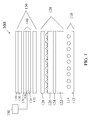
- FIG. 1 A schematic exploded view of an exemplary embodiment of a direct-lit LC display device 100 is presented in FIG. 1 .
- a display device 100 may be used, for example, in an LCD monitor or LCD-TV.
- the display device 100 is based on the use of a front panel assembly 130, comprising a LC panel 140, which typically comprises a layer of LC 136 disposed between panel plates 134.
- the plates 134 are often formed of glass, and may include electrode structures and alignment layers on their inner surfaces for controlling the orientation of the liquid crystals in the LC layer 136.
- the electrode structures are commonly arranged so as to define LC panel pixels, areas of the LC layer where the orientation of the liquid crystals can be controlled independently of adjacent areas.
- a color filter may also be included with one or more of the plates 134 for imposing color on the image displayed.
- An upper absorbing polarizer 138 is positioned above the LC layer 136 and a lower absorbing polarizer 132 is positioned below the LC layer 136.
- the absorbing polarizers 138, 132 and the LC panel 140 in combination control the transmission of light from the backlight 110 through the display 100 to the viewer.
- the absorbing polarizers 138, 132 may be arranged with their transmission axes perpendicular. When a pixel of the LC layer 136 is not activated, it may not change the polarization of light passing there through.
- the polarization of the light passing there through is rotated, so that at least some of the light that is transmitted through the lower absorbing polarizer 132 is also transmitted through the upper absorbing polarizer 138.
- Selective activation of the different pixels of the LC layer 136 results in the light passing out of the display at certain desired locations, thus forming an image seen by the viewer.
- the controller may include, for example, a computer or a television controller that receives and displays television images.
- One or more optional layers 139 may be provided over the upper absorbing polarizer 138, for example to provide mechanical and/or environmental protection to the display surface.
- the layer 139 may include a hardcoat over the absorbing polarizer 138.
- LC displays may operate in a manner different from that described above.
- the absorbing polarizers may be aligned parallel and the LC panel may rotate the polarization of the light when in an unactivated state.
- the basic structure of such displays remains similar to that described above.
- the backlight 110 includes a number of light sources 114 that generate the light that illuminates the LC panel 120.
- the light sources 114 used in a LCD-TV or LCD monitor are often linear, cold cathode, fluorescent tubes that extend across the display device 100.
- Other types of light sources may be used, however, such as filament or arc lamps, light emitting diodes (LEDs), flat fluorescent panels or external fluorescent lamps. This list of light sources is not intended to be limiting or exhaustive, but only exemplary.
- the backlight 110 may also include a reflector 112 for reflecting light propagating downwards from the light sources 114, in a direction away from the LC panel 140.
- the reflector 112 may also be useful for recycling light within the display device 100, as is explained below.
- the reflector 112 may be a specular reflector or may be a diffuse reflector.
- a specular reflector that may be used as the reflector 118 is Vikuiti® Enhanced Specular Reflection (ESR) film available from 3M Company, St. Paul, Minn.
- suitable diffuse reflectors include polymers, such as polyethylene terephthalate (PET), polycarbonate (PC), polypropylene, polystyrene and the like, loaded with diffusely reflective particles, such as titanium dioxide, barium sulphate, calcium carbonate and the like.
- PET polyethylene terephthalate
- PC polycarbonate
- diffusely reflective particles such as titanium dioxide, barium sulphate, calcium carbonate and the like.
- An arrangement 120 of light management layers is positioned between the backlight 110 and the front panel assembly 130.
- the light management layers affect the light propagating from backlight 110 so as to improve the operation of the display device 100 .
- the arrangement 120 of light management layers may include a diffuser plate 122.
- the diffuser plate 122 is used to diffuse the light received from the light sources, which results in an increase in the uniformity of the illumination light incident on the LC panel 140. Consequently, this results in an image perceived by the viewer that is more uniformly bright.
- the arrangement 120 of light management layers may also include a reflective polarizer 128.
- the light sources 114 typically produce unpolarized light but the lower absorbing polarizer 132 only transmits a single polarization state, and so about half of the light generated by the light sources 114 is not transmitted through to the LC layer 136.
- the reflecting polarizer 128, however, may be used to reflect the light that would otherwise be absorbed in the lower absorbing polarizer, and so this light may be recycled by reflection between the reflecting polarizer 128 and the reflector 112.
- At least some of the light reflected by the reflecting polarizer 128 may be depolarized, and subsequently returned to the reflecting polarizer 128 in a polarization state that is transmitted through the reflecting polarizer 128 and the lower absorbing polarizer 132 to the LC layer 136.
- the reflecting polarizer 128 may be used to increase the fraction of light emitted by the light sources 114 that reaches the LC layer 136, and so the image produced by the display device 100 is brighter.
- reflective polarizer any suitable type may be used, for example, multilayer optical film (MOF) reflective polarizers; diffusely reflective polarizing film (DRPF), such as continuous/disperse phase polarizers, wire grid reflective polarizers or cholesteric reflective polarizers.
- MOF multilayer optical film
- DRPF diffusely reflective polarizing film
- the arrangement 120 of light management layers may also include a light directing film 126.
- a light directing film is one that includes a surface structure that redirects off-axis light in a direction closer to the axis of the display. This increases the amount of light propagating on-axis through the LC layer 136, thus increasing the brightness of the image seen by the viewer.
- a prismatic light directing film which has a number of prismatic ridges that redirect the illumination light, through refraction and reflection.
- the present invention uses an arrangement of light management films at least one of which is supported by a controlled tensile force.
- the controlled tensile force is provided via a frame around the perimeter of the film.
- the tensile force is applied to the film, for example, by a crimping of the film between a top and bottom component of the frame.
- the film is initially held between the two frame components by a plurality of screws or snaps which protrude through holes or slots at various locations around the perimeter of the film and are subsequently connected to the frame of an LCD backlight.
- the screws or snaps once tightened also fasten the two components of the crimping frame together which maintains the tension on the film via the crimping affect.
- a cantilevered spring type mechanism protrudes from the bottom component of the crimping frame which helps maintain tension even during environmental testing. This optical element is useful in replacing the optical function of diffuser plates and optionally the other optical films in an LCD display.
- a "spring” is defined here as any mechanism that can substantially maintain a uniform tensile force over a range of motion. That range of motion must be at least as large a distance as the maximum expected change in dimension of the film under the design temperature and humidity ranges. Substantially maintained is defined here as maintaining the tensile force to at least 25% of the original force. Preferably the force can be maintained to at least 50% of the original force.
- film is defined here as a sheet of material that has a thickness of less than 500 um.
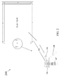
- the optical element 200 includes a polymeric optical diffuser film 214 and a two supporting frame components 210 and 212 located around the perimeter of the film. Perimeter is defined here as an imaginary continuous line drawn along all thin edges of the film. Typically for LDC displays there are 4 orthogonal edges creating a rectangular perimeter. Other optical films can also be added to the arrangement of light management layers above the polymeric optical diffuser film as will be illustrated in a subsequent figure.
- Figure 2 shows one means by which the optical diffuser film 214 is supported by a tensile force.
- Frame components 210 and 212 have a semi-circular groove and extension, respectively, which interlock together.
- Screws or snap pins 217 protrude through slots or holes in both the frame components 210 and 212 and the film 214.
- the screw or pin 217 is fastened to a frame of an LCD backlight 218.
- the two components of the frame 210 and 212 crimp the film creating a tension in the film.
- the initial tension in the film can be varied by varying the radius of the groove and extension in the frame components 210 and 212.
- the initial tension resulting from crimping can be reduced during elevated temperature such as during environmental testing.
- a cantilevered spring 213 is utilized. The spring 213 is deflected upon crimping and initial tensioning. If the film expands during elevated temperatures, the spring recoils acting to maintain tension in the film.
- the tensioned optical diffuser film 214 is self-supporting.
- self-supporting is defined as maintaining a planar uniformity of the film under the films own weight plus the addition of the weight of any other optical films to be used in the light management arrangement.
- Planar uniformity is defined as having an out of plane deflection from original position of less than 180 th of the length of the longest side of the diffuser film.
- the tensioned diffuser film 214 and one or more other light management layers may be included in a light management arrangement disposed between the backlight and the LCD panel.
- the tensioned diffuser film 214 provides a stable structure for supporting the light management arrangement.
- the tensioned film is not prone to warping like conventional diffuser plate systems.
- Exemplary embodiments of the polymeric optical diffuser film 214 include an asymmetric diffuser films.
- Such polymeric asymmetric diffuser films are either volume diffusers whereby the light diffusing structures are in the bulk of the film or they are surface diffusers whereby the light diffusing structures are on the surface of the film.
- Asymmetric volume diffusers have regions in the bulk of the film that comprise non-spherical domains that are at least somewhat aligned in terms of their major axes. These domains have a refractive index that differs from the matrix polymer of the film.
- Asymmetric volume diffusers may contain more than one diffusing region or layers.
- One or more of the diffusing regions may have an asymmetric diffusion profile.
- a rigid, substantially transparent material separates two diffusing regions.
- the asymmetrically diffusive regions are aligned such that the luminance uniformity of a backlight is improved.
- the spatial luminance profile of a backlight using a linear or grid array of light sources is substantially uniform through the use of one or more asymmetrically diffusing regions.
- the amount of diffusion in the x-z and y-z planes affects the luminance uniformity and the potential viewing angle of the backlight and display.
- the viewing angle is asymmetrically increased.
- the viewing angle of the display (related to the luminance and display contrast) can be increased in the x direction.
- the diffusion asymmetry introduced through one or more diffusing layers of an asymmetric diffuser film in a backlight can allow for greater control over the viewing angle and angular intensity profile of the display and the optical efficiency of the backlight and display system.
- amount of diffusion varies in the plane of the diffusing layer.
- the amount of diffusion varies in the plane perpendicular to the plane of the layer (z direction).
- the amount of diffusion is higher in the regions in close proximity of one or more of the light sources.
- the alignment of the axis of stronger diffusion in an asymmetric diffuser may be aligned parallel, perpendicular or at an angle with respect to a light source or edge of the backlight.
- the axis of stronger diffusion is aligned perpendicular to the length of a linear light source in a backlight.
- the particles within one or more asymmetric diffuser layers may be fibrous, spheroidal, cylindrical, other non-symmetric shape, or a combination of one or more of these shapes.
- the shape of the particles may be engineered such that substantially more diffusion occurs in the x-z plane than that in the y-z plane.
- the shape of the particles or domains may vary spatially along one or more of the x, y, or z directions. The variation may be regular, semi-random, or random.
- the particles within a diffusing layer may be aligned at an angle normal, parallel, or an angle with respect to an edge of the diffusing layer or a linear light source or array of light sources.
- the particles in a diffusing layer are substantially aligned along one axis that is parallel to a linear array of light sources.
- the particles may be contained within the volume of a continuous phase material or they may be protruding from the surface or substantially planar surface of the continuous phase material.
- the particles described herein in one or more light diffusing layers may be in a low or high concentration.
- a concentration of particles When the diffusion layer is thick, a lower concentration of particles is needed.
- the light diffusing layer When the light diffusing layer is thin, a higher concentration of particles is needed.
- the concentration of the dispersed phase may be from less than 1% by weight to 50% by weight. In certain conditions, a concentration of particles higher than 50% may be achieved by careful selection of materials and manufacturing techniques. A higher concentration permits a thinner diffusive layer and as a result, a thinner backlight and display.
- the refractive index difference between the particles and the matrix may be very small or large. If the refractive index difference is small, then a higher concentration of particles may be required to achieve sufficient diffusion in one or more directions. If the refractive index difference is large, then fewer particles (lower concentration) are typically required to achieve sufficient diffusion and luminance uniformity.
- the refractive index difference between the particles and the matrix may be zero or larger than zero in one or more of the x, y, or z directions.
- the refractive index of the individual polymeric phases is one factor that contributes to the degree of light scattering by the film. Combinations of low and high refractive index materials result in larger diffusion angles. In cases where birefringent materials are used, the refractive indexes in the x, y, and z directions can each affect the amount of diffusion or reflection in the processed material. In some applications, one may use specific polymers for specific qualities such as thermal, mechanical, or low-cost, however, the refractive index difference between the materials (in the x, y, or z directions, or some combination thereof) may not be suitable to generate the desired amount of diffusion or other optical characteristic such as reflection.
- small particles typically less than 1 micron in size to increase or decrease the average bulk refractive index.
- light does not directly scatter from these added particles, and the addition of these particles does not substantially increase the absorption or backscatter.
- Additive particles can increase or decrease the average refractive index based on the amount of the particles and the refractive index of the polymer to which they are added, and the effective refractive index of the particle.
- Such additives can include: aerogels, sol-gel materials, silica, kaolin, alumina, fine particles of MgF 2 (index of refraction is 1.38), SiO 2 (index of refraction is 1.46), AlF 3 (index of refraction is 1.33-1.39), CaF 2 (index of refraction is 1.44), LiF (index of refraction is 1.36-1.37), NaF (index of refraction is 1.32-1.34) and ThF 4 (index of refraction is 1.45-1.5) or the like can be considered.
- fine particles having a high index of refraction may be used such as fine particles of titania (TiO 2 ) or zirconia (ZrO 2 ) or other metal oxides.
- One or more surfaces of the diffusing layer may contain a non-planar surface.
- the surface profile may contain protrusions or pits that may range from 1 nm to 3 mm in the x, y, or z directions.
- the profile or individual features may have periodic, random, semi-random, or other uniform or non-uniform structure.
- the surface features may be designed to provide function to the diffuser plate such as collimation, anti-blocking, refraction, symmetric diffusion, asymmetric diffusion or diffraction.
- the surface features are a linear array of prismatic structures that provide collimation properties.
- the surface contains hemispherical protrusions that prevent wet-out, provide anti-blocking properties, or light collimating properties.
- One or more surfaces of the diffusing layer may contain surface profiles that provide collimation properties.
- the collimation properties direct light rays incident from large angles into angles closer to the display normal (smaller angles).
- the features may be in the form of a linear array of prisms, an array of pyramids, an array of cones, an array of hemispheres or other feature that is known to direct more light into the direction normal to the surface of the backlight.
- the array of features may be regular, irregular, random, ordered, semi-random or other arrangement where light is can be collimated through refraction, reflection, total internal reflection, diffraction, or scattering.
- the enhanced asymmetric diffuser of this invention may contain materials, additives, components, blends, coatings, treatments, layers or regions that provide additional optical, mechanical, environmental, thermal or electrical benefits.
- the properties of the diffuser film may include one or more of the following: Optical: increased optical throughput, increased/decreased diffusion along one or more axis, reduced or increased birefringence, increased luminance uniformity, improved color stability, reduced haze; Mechanical/Physical: increase rigidity, reduced thickness, reduced weight, increased scratch resistance, reduced/increased pencil hardness, anti-blocking features; Environment: reduced warpage, increased light resistance, increased moisture resistance, increased light resistance, increased ultraviolet absorption; Thermal: increased thermal resistance, increased softening temperature; Electrical: decreased surface resistance
- Asymmetric surface diffusers have structures on the surface of the film that comprise holographic structures or non-spherical domains that are at least somewhat aligned in terms of their major axes. Holographic structures are typically embossed onto the film from recorded material tools. Non-spherical domains have a refractive index that differs from the matrix polymer of the film. One embodiment of the non-spherical domains that are at least somewhat aligned are a close-packed array of anamorphic microlenses. "Anamorphic" refers to a feature producing different magnification of an image in each of two perpendicular directions.
- the diffuser film may be composed of one or more light scattering regions containing a continuous phase and a dispersed phase.
- the diffuser film may contain a region of light scattering surface features that exhibit asymmetric scattering properties.
- one or more of the diffusing layers may be an adhesive joining two or more components of the asymmetric diffuser film.
- the film may also contain a substrate that may be substantially optically transparent and a continuous phase. The materials chosen for the substrate, dispersed, or continuous phases may be one or more polymeric or inorganic materials.
- Such polymers include, but are not limited to acrylics, styrenics, olefins, polycarbonates, polyesters, cellulosics, polyester-carbonates, and the like. Specific examples include poly(methyl methacrylate) and copolymers thereof, polystyrene and copolymers thereof, poly(styrene-co-acrylonitrile), polyethylene and copolymers thereof, polypropylene and copolymers thereof, poly(ethylenepropylene) copolymers, poly(vinyl acetate) and copolymers thereof, poly(vinyl alcohol) and copolymers thereof, bisphenol-A polycarbonate and copolymers thereof, poly(ethylene terephthalate) and copolymers thereof, poly(ethylene 2,6-naphthalenedicarboxylate) and copolymers thereof, polyarylates, polyamide copolymers, poly(vinyl chloride), cellulose acetate, cellulose acetate butyrate, cellulose acetate propionat
- the methacrylates include but are not limited to polymethacrylates such as poly(methyl methacrylate) , poly(ethyl methacrylate), poly(propyl methacrylate), poly(butyl methacrylate), poly(isobutyl methacrylate), methyl methacrylate-methacrylic acid copolymer, methyl methacrylate-acrylate copolymers, and methyl methacrylate-styrene copolymers (e.g., MS resins).
- polymethacrylates such as poly(methyl methacrylate) , poly(ethyl methacrylate), poly(propyl methacrylate), poly(butyl methacrylate), poly(isobutyl methacrylate), methyl methacrylate-methacrylic acid copolymer, methyl methacrylate-acrylate copolymers, and methyl methacrylate-styrene copolymers (e.g., MS resins).
- MS resins
- the preferred methacrylic resins include poly(alkyl methacrylate)s and copolymers thereof
- the most preferred methacrylic resins include poly(methyl methacrylate) and copolymers thereof
- the acrylates include but are not limited to poly(methyl acrylate), poly(ethyl acrylate), and poly(butyl acrylate), and copolymers thereof.
- styrenic resins are suitable for polymeric phases of the present invention.
- Such resins include vinyl aromatic polymers, such as syndiotactic polystyrene.
- Syndiotactic vinyl aromatic polymers useful in the present invention include poly(styrene), poly(alkyl styrene)s, poly (aryl styrene)s, poly(styrene halide)s, poly(alkoxy styrene)s, poly(vinyl ester benzoate), poly(vinyl naphthalene) , poly(vinylstyrene), and poly(acenaphthalene), as well as the hydrogenated polymers and mixtures or copolymers containing these structural units.
- poly(alkyl styrene)s include the isomers of the following: poly(methyl styrene), poly(ethyl styrene), poly(propyl styrene), and poly(butyl styrene).
- poly(aryl styrene)s include the isomers of poly(phenyl styrene).
- examples include the isomers of the following: poly(chlorostyrene), poly(bromostyrene), and poly(fluorostyrene).
- poly(alkoxy styrene)s include the isomers of the following: poly(methoxy styrene) and poly(ethoxy styrene).
- the preferred styrene resin polymers are: polystyrene, poly(p-methyl styrene) , poly(m-methyl styrene), poly(p-tertiary butyl styrene), poly(p-chlorostyrene), poly(m-chloro styrene), poly(p-fluoro styrene), and copolymers of styrene and p-methyl styrene.
- the most preferred styrenic resins include polystyrene and copolymers thereof.
- polyester and copolyester resins are suitable for phases of the present invention.
- Such resins include poly(ethylene terephthalate) and copolymers thereof, poly(ethylene 2,6-naphthalenedicarboxylate) and copolymers thereof, poly(1,4-cyclohexandimethylene terephthalate) and copolymers thereof, and copolymers of poly(butylene terephthalate).
- the acid component of the resin can comprise terephthalic acid, isophthalic acid, 2,6-naphthalenedicarboxylic acid or a mixture of said acids.
- polyesters and copolyesters can be modified by minor amounts of other acids or a mixture of acids (or equivalents esters) including, but not limited to, phthalic acid, 4,4'-stilbene dicarboxylic acid, 2,6-naphthalenedicarboxylic acid, oxalic acid, malonic acid, succinic acid, glutaric acid, adipic acid, pimelic acid, suberic acid, azelaic acid, sebacic acid, 1,12-dodecanedioic acid, dimethylmalonic acid, cis-1,4-cyclohexanedicarboxylic acid and trans-1,4-cyclohexanedicarboxylic acid.
- acids or a mixture of acids (or equivalents esters) including, but not limited to, phthalic acid, 4,4'-stilbene dicarboxylic acid, 2,6-naphthalenedicarboxylic acid, oxalic acid, malonic acid, succinic acid, glutaric acid, a
- the glycol component of the resin can comprise ethylene glycol, 1,4-cyclohexanedimethanol, butylene glycol, or a mixture of said glycols.
- the copolyesters can also be modified by minor amounts of other glycols or a mixture of glycols including, but not limited to, 1,3-trimethylene glycol, 1,4-butanediol, 1,5-pentanediol, 1,6-hexanediol, 1,7-heptanediol, 1,8-octanediol, 1,9-nonanediol, 1,10-decanediol, 1,12-dodecanediol, neopentyl glycol, 2,2,4,4-tetramethyl-1,3-cyclobutanediol, diethylene glycol, bisphenol A and hydroquinone.
- the preferred polyester resins include copolyesters formed by the reaction of a mixture of terephthalic acid and isophthalic acid or their equivalent esters with a mixture of 1,4-cyclohexanedimethanol and ethylene glycol.
- the most preferred polyester resins include copolyesters formed by the reaction of terephthalic acid or its equivalent ester with a mixture of 1,4-cyclohexanedimethanol and ethylene glycol.
- Polycarbonate and copolycarbonate resins are suitable for phases of the present invention.
- Polycarbonate resins are typically obtained by reacting a diphenol with a carbonate precursor by solution polymerization or melt polymerization.
- the diphenol is preferably 2,2-bis(4-hydroxyphenyl)propane (so-called "bisphenol A”) but other diphenols may be used as part or all of the diphenol.
- Examples of the other diphenol include 1,1-bis(4-hydroxyphenyl)ethane, 1,1-bis(4-hydroxyphenyl)cyclohexane, 2,2-bis(4-hydroxy-3,5-dimethylphenyl-)propane, 2,2-bis(4-hydroxy-3-methylphenyl)propane, bis(4-hydroxyphenyl) sulfideandbis(4-hydroxyphenyl)sulfone.
- the polycarbonate resin is preferably a resin which comprises bisphenol A in an amount of 50 mol % or more, particularly preferably 70 mol % or more of the total of all the diphenols.
- Examples of the carbonate precursor include phosgene, diphenyl carbonate, bischloroformates of the above diphenols, di-p-tolyl carbonate, phenyl-p-tolyl carbonate, di-p-chlorophenyl carbonate and dinaphthyl carbonate. Out of these, phosgene and diphenyl carbonate are particularly preferred.
- poly(alkylene) polymers are suitable for phases of the present invention.
- Such polyalkylene polymers include polyethylene, polypropylene, polybutylene, polyisobutylene, poly(4-methyl) pentene), copolymers thereof, chlorinated variations thereof, and fluorinated variations thereof.
- Particular cellulosic resins are suitable for phases of the present invention.
- Such resins include cellulose acetate, cellulose acetate butyrate, cellulose acetate propionate, cellulose propionate, ethyl cellulose, cellulose nitrate.
- Cellulosic resins including a variety of plasticizers such as diethyl phthalate are also within the scope of the present invention.
- polymeric optical diffuser film 214 include semi-crystalline polymer matrix containing voids and void initiating particles or simply diffusive particles like inorganic particles or cross-linked polymeric beads.
- a semi-crystalline polymer matrix is preferred as it may be substantially transparent to visible light, can be readily stretched, and can possess dimensional stability having a shrinkage of less than 1.0% after being tested at elevated temperatures up to 85C.
- Preferable polymers to meet all these criteria are polyesters and their copolymers. Most preferred are poly(ethylene terephthalate) (PET); poly(ethylene naphthalate)(PEN)polyesters and any of their copolymers. PET is most suitable as it is much lower in cost than PEN.
- the void initiating particles may be any type of particle that is incompatible with the matrix polymer. These particles can be inorganic or organic. Inorganic particles can include any of calcium carbonate, barium sulfate, titanium dioxide, or any other inorganic compound that can be melt blended into a polymer. Typical organic void initiating particles are polymers that are immiscible with the matrix polymer. These are preferred as resin pellets of these immiscible polymers can be simply dry blended with the resin pellets of the matrix polymer and extruded together to form a cast film. Inorganic particles require a pre-mixing or melt compounding, which adds processing cost. Preferred organic void initiating particles are polyolefins. Most preferred is polypropylene.
- the void initiating particles should be added so as to produce enough diffusivity to function as a diffuser yet not be so opaque that the optical luminance of the LCD display is significantly reduced.
- Preferred loadings of the void initiating particles are 3 to 25 wt % of the entire film. The most preferred loadings are 10 to 20 wt%.
- the optical diffuser film 214 may be provided with protection from ultraviolet (UV) light, for example by including UV absorbing material or material in one of the layers that is resistant to the effects of UV light.
- UV absorbing materials are available commercially, including, e. g., Cyasorb® UV-1164, available from Cytec Technology Corporation of Wilmington, Del., and Tinuvin® 1577, available from Ciba Specialty Chemicals of Tarrytown, N.Y.
- another preferred embodiment of the polymeric optical diffuser film 214 is one with spatially varying domains in the film having higher or lower loadings of diffusive particles or voids.
- the diffusive domains in these spatially varying diffuser films can be either symmetric or asymmetric in nature. This can be very useful by enabling the film or films supported by the controlled force to be located closer to the light sources (typically ccfl's) of a backlit LCD display. In one case, the closer spacing is enabled by having stripes of higher diffusive property being aligned directly over the linear ccfl light source resulting in uniform light emission from the film.
- HALS hindered amine light stabilizing composition
- Suitable HALS compositions are available commercially, for example, under the "Tinuvin” tradename from Ciba Specialty Chemicals Corporation of Tarrytown, N.Y.
- Tinuvin 622 is Tinuvin 622.
- the frame components 210 and 212 can comprise any rigid material, preferably plastic.
- the spring can comprise any rigid material, preferably plastic, and is typically fabricated integral with the bottom frame 210.
- the optical element 200 of Figure 2 can be used in place of the diffuser plate of conventional LCD displays.
- the optical element 300 discloses, in addition to a diffuser film 314 being tensioned, another film, a light collimating diffuser film 316, also being tensioned.
- the film 314 is an optical diffuser film as described for that described for film 214 in Figure 2 .
- a third film 315, a prismatic light directing film is supported between the two tensioned films 314 and 316.
- the optical element 300 of Figure 3 can be used in place of the diffuser plate and the optional optical films of conventional LCD displays.
- the optical element 400 utilizes the frame of the LCD backlight unit 418 as the lower component of the crimping frame. This is done by integrating the semi-circular groove into the backlight unit of the LCD. Also, optical element 400 utilizes a separate cantilevered spring element 413, sandwiched between the top crimping frame component 412 and the back light unit 418.
- the film 414 is also an optical diffuser film as described for that of film 214 in Figure 2 and could optionally be more than one film. Also, the snap pin 417 of optical element 400 is integral to the top crimping frame.
- the top crimping frame 412 and snap pin 417 can be any rigid material but preferably are polymeric and produced by an injection molding process.
- the cantilevered spring element 413 can comprise plastic or metal.
- the optical element 400 of Figure 4 can be used in place of the diffuser plate and the optional optical films of conventional LCD displays.
- the optical element 500 is an arrangement of at least two light management films comprising a large space between the bottom film 514 and the upper film or films 516.
- the space is maintained by the addition of a second cantilevered spring element 511 which acts to force the elevation of the lower film 514 below that of the upper optical film or films 516.
- the elevation of the upper optical film or films is maintained by the cantilevered spring 516 which pushes the upper films 516 in the opposite direction as that of spring 511.
- Lower film 514 is a polymeric optical diffuser film and can comprise the same materials as described previously for diffuser film 214.
- diffuser film 514 has spatially varying domains of higher diffusive stripes 509 arranged linearly appearing as stripes in the film.
- These higher diffusive stripes 509 are preferably formed by two or more layers of diffusive particles in a polymer matrix having different widths to thus form a gradient in the diffusivity across the width of the stripe.
- the backlight unit frame 518 has a semi-circular groove so as to act as the lower crimping frame component of the crimping frame.
- Backlight frame 518 can be designed to hold the tensioned films 514 and 516 at a much closer overall spacing to the ccfl light sources 519 than that of the backlight frame 418 in Fig 4 .
- the top crimping frame component 512 and snap pin 517 can be any rigid material but preferably are polymeric and produced by an injection molding process.
- the optical element 500 of Figure 5 can be used in place of the diffuser plate and the optional optical films of conventional LCD displays.
- the optical element 600 discloses a two dimensional array of LED light sources 619 are used. Based on this, the lower optical diffuser film 614 employs a circular dot pattern of higher diffusive domains 609 which align directly over each LED 619. These circular dots are preferably two or more layers of circular dots with different diameter to thus form a radial gradient in the diffusivity across the width of the dots.
- the optical diffuser film 614 can comprise the same material as that described for diffuser film 214 in Fig 2 .
- the optical element 600 of Figure 6 can be used in place of the diffuser plate and the optional optical films of conventional LCD displays.
- any of the embodiments where more than one optical film is constrained by the frame or the tensioned films typically none of the optical films are adhered to each other. There may be benefit for two optical films to be adhered to each other from a cost of manufacturing standpoint but typically one or more of the optical films are not adhered to each other.
- an optical element comprising at least one optical film which is supported under a controlled tensile force by a tensioning mechanism such that the film maintains flatness and a high degree of tension over the design temperature and humidity ranges of the optical element. Maintaining a high degree of flatness of the tensioned film requires a unique design of the tensioning mechanism and is the essence of the present invention. It is further the object of the present invention to provide a low cost means to provide the tension to the at least one optical film.
- the optical element provides the optical smoothing function of previous plate diffusers at a very low cost.
- the optical element is unique in that it provides a high level of optical function and meets surface flatness requirements under specified thermal and humidity testing even at low thicknesses.
- the optical element comprises a supporting frame around the perimeter of the at least one optical film that is supported by a controlled tensile force.
- Other embodiments of the invention include other light management films also constrained by the supporting frame.
- a commercial LCD TV was procured.
- the TV chosen was a 42" LG Philips LCD TV, model 42LB5D.
- the LC panel and the arrangement of light management films were removed from the TV exposing an array of CCFLs in the backlight unit.
- the backlight unit was next outfitted with a tensioned support arrangement of the present invention as that shown in Fig. 3 .
- the center film used in the installation as shown in Fig. 3 was the same conventional prismatic collimation film that was originally provided in the 42" LG Phillips TV.
- the top film used in the installation as shown in Figure 3 was a 100 um bead coated diffuser (Kimoto Ltd's 100-TL4 Diffusion Film).
- the bottom film(immediately above the CCFLs) used in the tensioned stack-up was a volumetric optical diffuser. This film was made by first melt compounding 5.0 microbeads of cross-linked siloxane particles (Tospearl 145A from Momentive Performance Materials Inc.) into Polyethylene terephthalate (PET #7352 from Eastman Chemicals).
- Both the Polyethylene terephthalate resin pellets and the microbeads were first dried at 165°C in a desiccant dryer for 24 hours. They were then fed into a 27mm twin screw compounder with the beads being loaded at a 30% by wt. to the compounded blend. The extrudate from the compounder was fed through a water bath and then pelletized.
- the compounded pellets and the more PET 7352 was dried at 165°C in a desiccant dryer for 24 hours.
- the PET pellets and the compounded pellets were dry blended with the compounded pellets making up 16% by wt. of the dry blend and the PET 84% by wt.
- the blend was melted at 275°C and fed by a plasticating screw extruder into an extrusion die manifold to produce a melt stream which was rapidly quenched on a chill roll after issuing from the die.
- the throughput of the extruder it was possible to adjust the thickness of the resulting cast sheet. In this case the thickness of the cast sheet was approximately 750 ⁇ m.
- the cast sheet was first oriented in the machine direction by stretching at a ratio of 3.0 and a temperature of 110° C. This sheet was then oriented in the transverse direction in a tenter frame at a ratio of 3.3 and a temperature of 100°C without tearing. The stretched sheet was then heat set at 220°C. The final film thickness was approximately 100 ⁇ m.
- the 3 films as just described were assembled into a tensioned frame design as that shown in Figure 3 .
- the top component of the crimping frame was machined from aluminum.
- the bottom component of the crimping frame was produced using a stereo-lithographic process and a UV curable polymer.
- the tensioned support arrangement as described in Figure 3 using the films described above was fastened to the backlight unit frame around the periphery of the exposed CCFLs using screws spaced every 3 inches around the crimping frame. As the screws were tightened the two outer films were tensioned as they were crimped between the crimping frame components.
- the cantilevered spring was partially bent by the films resulting in even higher tension in the films.
- the resulting film stack appeared very flat and free of any buckling. When illuminating the CCFLs the light emitting from the films was very bright and uniform with no apparent waving or warping of the films.
- the assembled backlight unit with the tensioned films was next subjected to two different thermal test conditions.
- the first test was to place the assembled back light into an oven at 65°C for 15 minutes. Upon removing the backlight from the oven the films still appeared very flat and free of any buckling. When illuminating the CCFLs there still was no apparent waving or warping of the films.
- the second test done consisted of placing insulation directly over the films of the backlight and illuminating the CCFLs at maximum intensity for 15 minutes. Upon removing the insulation there still was no apparent waving or warping of the films.
Landscapes
- Physics & Mathematics (AREA)
- Nonlinear Science (AREA)
- Mathematical Physics (AREA)
- Chemical & Material Sciences (AREA)
- Crystallography & Structural Chemistry (AREA)
- General Physics & Mathematics (AREA)
- Optics & Photonics (AREA)
- Optical Elements Other Than Lenses (AREA)
- Liquid Crystal (AREA)
- Planar Illumination Modules (AREA)
- Mounting And Adjusting Of Optical Elements (AREA)
Applications Claiming Priority (1)
| Application Number | Priority Date | Filing Date | Title |
|---|---|---|---|
| US12/069,748 US20090201441A1 (en) | 2008-02-13 | 2008-02-13 | Tensioned optical element having crimping frame and spring |
Publications (1)
| Publication Number | Publication Date |
|---|---|
| EP2090922A1 true EP2090922A1 (de) | 2009-08-19 |
Family
ID=40671437
Family Applications (1)
| Application Number | Title | Priority Date | Filing Date |
|---|---|---|---|
| EP09152718A Withdrawn EP2090922A1 (de) | 2008-02-13 | 2009-02-12 | Gespanntes optisches Element mit Crimprahmen und -feder |
Country Status (6)
| Country | Link |
|---|---|
| US (1) | US20090201441A1 (de) |
| EP (1) | EP2090922A1 (de) |
| JP (1) | JP2009230118A (de) |
| KR (1) | KR20090087842A (de) |
| CN (1) | CN101581804A (de) |
| TW (1) | TW200938899A (de) |
Cited By (1)
| Publication number | Priority date | Publication date | Assignee | Title |
|---|---|---|---|---|
| WO2022063609A1 (en) | 2020-09-22 | 2022-03-31 | Signify Holding B.V. | Tensioner for optical films |
Families Citing this family (23)
| Publication number | Priority date | Publication date | Assignee | Title |
|---|---|---|---|---|
| KR20090057573A (ko) * | 2007-12-03 | 2009-06-08 | 삼성전자주식회사 | 백라이트유닛 및 이를 갖는 평판표시장치 |
| US8568002B2 (en) * | 2010-03-05 | 2013-10-29 | Southpac Trust International Inc., Trustee of the LDH Trust | Light diffusion and condensing fixture |
| KR20130019597A (ko) * | 2011-08-17 | 2013-02-27 | 삼성전자주식회사 | 액정패널조립체 및 그를 구비한 액정디스플레이 장치 |
| US8907231B2 (en) * | 2012-07-18 | 2014-12-09 | Nokia Corporation | Display arrangement |
| CN103676288A (zh) * | 2012-09-10 | 2014-03-26 | 宏腾光电股份有限公司 | 广色域膜及其制作方法和具有广色域膜的显示装置 |
| US20140176859A1 (en) * | 2012-12-20 | 2014-06-26 | Extend Optronics Corp. | Wide-color gamut film, display apparatus with the wide-color gamut film, and method for manufacturing the film |
| CN104009168A (zh) * | 2013-02-26 | 2014-08-27 | 海洋王照明科技股份有限公司 | 一种有机电致发光器件及其制备方法 |
| US9348174B2 (en) | 2013-03-14 | 2016-05-24 | Manufacturing Resources International, Inc. | Rigid LCD assembly |
| CN112328127B (zh) * | 2014-09-12 | 2024-10-11 | 积水保力马科技株式会社 | 传感片及传感面板 |
| US10649273B2 (en) | 2014-10-08 | 2020-05-12 | Manufacturing Resources International, Inc. | LED assembly for transparent liquid crystal display and static graphic |
| KR102131663B1 (ko) * | 2015-06-26 | 2020-07-08 | 삼성전자주식회사 | 디스플레이 장치 |
| WO2017038084A1 (ja) | 2015-09-01 | 2017-03-09 | パナソニックIpマネジメント株式会社 | 映像表示装置 |
| WO2017038080A1 (ja) | 2015-09-01 | 2017-03-09 | パナソニックIpマネジメント株式会社 | 映像表示装置 |
| US10261362B2 (en) | 2015-09-01 | 2019-04-16 | Manufacturing Resources International, Inc. | Optical sheet tensioner |
| JP6688956B2 (ja) * | 2015-09-01 | 2020-04-28 | パナソニックIpマネジメント株式会社 | 映像表示装置 |
| WO2017038085A1 (ja) | 2015-09-01 | 2017-03-09 | パナソニックIpマネジメント株式会社 | 画像表示装置 |
| EP3346322B1 (de) | 2015-09-01 | 2020-09-30 | Panasonic Intellectual Property Management Co., Ltd. | Videoanzeigevorrichtung |
| WO2017038083A1 (ja) | 2015-09-01 | 2017-03-09 | パナソニックIpマネジメント株式会社 | 画像表示装置 |
| TWI588570B (zh) * | 2016-03-28 | 2017-06-21 | 友達光電股份有限公司 | 顯示裝置及使用之背光模組 |
| DE102018205315B4 (de) * | 2018-04-09 | 2024-06-20 | Clay Paky S.R.L. | Optisches System mit Diffusoren und Wabenkondensoren |
| CN109375414B (zh) * | 2018-10-23 | 2020-11-10 | 惠州市华星光电技术有限公司 | 一种背光模组 |
| KR102778475B1 (ko) * | 2019-12-13 | 2025-03-12 | 삼성디스플레이 주식회사 | 디스플레이 장치 |
| US12429726B1 (en) | 2023-10-02 | 2025-09-30 | Manufacturing Resources International, Inc. | Optical stack with a liquid crystal layer and a micro lens array, electronic display assembly, and related methods |
Citations (5)
| Publication number | Priority date | Publication date | Assignee | Title |
|---|---|---|---|---|
| JPH08338990A (ja) * | 1995-06-12 | 1996-12-24 | Omron Corp | 表示素子及びその製造方法並びに液晶表示装置 |
| EP1517171A1 (de) * | 2003-09-18 | 2005-03-23 | SANYO ELECTRIC Co., Ltd. | Flüssigkristallanzeige-Vorrichtung |
| US20060082699A1 (en) | 2004-10-15 | 2006-04-20 | 3M Innovative Properties Company | Liquid crystal displays with laminated diffuser plates |
| US20060290253A1 (en) * | 2005-06-23 | 2006-12-28 | Fusion Optix, Inc. | Enhanced Diffusing Plates, Films and Backlights |
| JP2007115425A (ja) * | 2005-10-18 | 2007-05-10 | Toray Ind Inc | 液晶ディスプレイ用バックライト |
-
2008
- 2008-02-13 US US12/069,748 patent/US20090201441A1/en not_active Abandoned
-
2009
- 2009-02-12 EP EP09152718A patent/EP2090922A1/de not_active Withdrawn
- 2009-02-13 TW TW098104607A patent/TW200938899A/zh unknown
- 2009-02-13 CN CNA2009101346608A patent/CN101581804A/zh active Pending
- 2009-02-13 JP JP2009030683A patent/JP2009230118A/ja not_active Withdrawn
- 2009-02-13 KR KR1020090012153A patent/KR20090087842A/ko not_active Withdrawn
Patent Citations (5)
| Publication number | Priority date | Publication date | Assignee | Title |
|---|---|---|---|---|
| JPH08338990A (ja) * | 1995-06-12 | 1996-12-24 | Omron Corp | 表示素子及びその製造方法並びに液晶表示装置 |
| EP1517171A1 (de) * | 2003-09-18 | 2005-03-23 | SANYO ELECTRIC Co., Ltd. | Flüssigkristallanzeige-Vorrichtung |
| US20060082699A1 (en) | 2004-10-15 | 2006-04-20 | 3M Innovative Properties Company | Liquid crystal displays with laminated diffuser plates |
| US20060290253A1 (en) * | 2005-06-23 | 2006-12-28 | Fusion Optix, Inc. | Enhanced Diffusing Plates, Films and Backlights |
| JP2007115425A (ja) * | 2005-10-18 | 2007-05-10 | Toray Ind Inc | 液晶ディスプレイ用バックライト |
Cited By (2)
| Publication number | Priority date | Publication date | Assignee | Title |
|---|---|---|---|---|
| WO2022063609A1 (en) | 2020-09-22 | 2022-03-31 | Signify Holding B.V. | Tensioner for optical films |
| US12032198B2 (en) | 2020-09-22 | 2024-07-09 | Signify Holding, B.V. | Tensioner for optical films |
Also Published As
| Publication number | Publication date |
|---|---|
| KR20090087842A (ko) | 2009-08-18 |
| CN101581804A (zh) | 2009-11-18 |
| JP2009230118A (ja) | 2009-10-08 |
| TW200938899A (en) | 2009-09-16 |
| US20090201441A1 (en) | 2009-08-13 |
Similar Documents
| Publication | Publication Date | Title |
|---|---|---|
| EP2090922A1 (de) | Gespanntes optisches Element mit Crimprahmen und -feder | |
| EP2023166B1 (de) | Optisches Element mit rückgehaltenem asymmetrischen Diffusor | |
| US8033674B1 (en) | Optical components and light emitting devices comprising asymmetric scattering domains | |
| US20060290253A1 (en) | Enhanced Diffusing Plates, Films and Backlights | |
| EP2116873A2 (de) | Optischer Streufilm mit linearen Domänen unterschiedlicher Streuung | |
| US7327415B2 (en) | Microvoided light diffuser | |
| US7597461B2 (en) | Tensioned optical element and display | |
| US20080192352A1 (en) | Optical diffuser film and light assembly | |
| KR20080109732A (ko) | 홈이 있는 광학 판을 갖는 광학 디스플레이 | |
| US20030118807A1 (en) | Stacked microvoided light diffuser | |
| CN101251679B (zh) | 具有自支撑膜组件的光学器件 |
Legal Events
| Date | Code | Title | Description |
|---|---|---|---|
| PUAI | Public reference made under article 153(3) epc to a published international application that has entered the european phase |
Free format text: ORIGINAL CODE: 0009012 |
|
| 17P | Request for examination filed |
Effective date: 20090212 |
|
| AK | Designated contracting states |
Kind code of ref document: A1 Designated state(s): AT BE BG CH CY CZ DE DK EE ES FI FR GB GR HR HU IE IS IT LI LT LU LV MC MK MT NL NO PL PT RO SE SI SK TR |
|
| AX | Request for extension of the european patent |
Extension state: AL BA RS |
|
| 17Q | First examination report despatched |
Effective date: 20090929 |
|
| AKX | Designation fees paid |
Designated state(s): DE FR GB |
|
| STAA | Information on the status of an ep patent application or granted ep patent |
Free format text: STATUS: THE APPLICATION IS DEEMED TO BE WITHDRAWN |
|
| 18D | Application deemed to be withdrawn |
Effective date: 20100210 |