EP2090941A1 - Mechanischer Oszillator - Google Patents
Mechanischer Oszillator Download PDFInfo
- Publication number
- EP2090941A1 EP2090941A1 EP08101699A EP08101699A EP2090941A1 EP 2090941 A1 EP2090941 A1 EP 2090941A1 EP 08101699 A EP08101699 A EP 08101699A EP 08101699 A EP08101699 A EP 08101699A EP 2090941 A1 EP2090941 A1 EP 2090941A1
- Authority
- EP
- European Patent Office
- Prior art keywords
- connecting member
- blade
- oscillator according
- zero
- oscillator
- Prior art date
- Legal status (The legal status is an assumption and is not a legal conclusion. Google has not performed a legal analysis and makes no representation as to the accuracy of the status listed.)
- Granted
Links
Images

Classifications
-
- G—PHYSICS
- G04—HOROLOGY
- G04B—MECHANICALLY-DRIVEN CLOCKS OR WATCHES; MECHANICAL PARTS OF CLOCKS OR WATCHES IN GENERAL; TIME PIECES USING THE POSITION OF THE SUN, MOON OR STARS
- G04B1/00—Driving mechanisms
- G04B1/10—Driving mechanisms with mainspring
- G04B1/22—Compensation of changes in the motive power of the mainspring
-
- G—PHYSICS
- G04—HOROLOGY
- G04B—MECHANICALLY-DRIVEN CLOCKS OR WATCHES; MECHANICAL PARTS OF CLOCKS OR WATCHES IN GENERAL; TIME PIECES USING THE POSITION OF THE SUN, MOON OR STARS
- G04B17/00—Mechanisms for stabilising frequency
Definitions
- the present invention relates to mechanical oscillators, especially those which equip the timepieces. It relates, more particularly, such an oscillator with a device for adjusting and correcting its frequency.
- a first object of the invention is to provide an oscillator for a mechanical watch equipped with means for correcting the isochronism defect induced by the variations of the engine torque of the mainspring, according to a principle of correction as a function of the amplitude.
- the object of the invention is to be able to maintain a constant frequency of the oscillator, in its useful range of operation, based on the amplitude variations to correct an effect comparable to a non-linearity of the spring of recall.
- the present invention relates to a mechanical oscillator of the type comprising an oscillating system formed of a rocker arm and its return spring.
- This oscillator further comprises a frequency correction device formed of at least a first and a second element fixed respectively to its frame and to the oscillating system, the first of these elements comprising an elastic flexible blade fixed by one of its ends. and the second being a connecting member weighing, during part of the oscillation, against the free end of said blade.
- the oscillator according to the invention may comprise only one flexible blade but, advantageously, it comprises two acting in opposition on the connecting member and offset, with respect to each other, a half-cycle of the oscillation, in order to symmetrize the characteristic of the return correction as a function of the deflection.
- the single blade - or both blades - is fixed - or are fixed - to the frame via an interface allowing a position adjustment in translation and rotation.
- the single blade - or both blades - is - or are - in contact, at a non-zero pressure, with the connecting member when the balance is in the neutral position, that is to say say when its angle relative to its rest position is equal to zero, so as to obtain an increase in the frequency when the amplitude decreases (negative correction).
- the connecting member may be fixed to the balance either directly or by an intermediate piece of the return spring oscillating at a reduced deflection angle relative to that of the balance.
- the oscillator may advantageously comprise a fixed stop located opposite the connecting member for a deflection angle of the balance relative to its rest position equal to zero, and intended to exert a prestress on said blade when said member is not in contact.
- the oscillator for mechanical watch according to the invention is particularly applicable to the exhaust system described in the document EP 1 736 838 already quoted, in particular at figure 2a whose content is integrated in the present description.
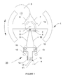
- a pendulum 1 (partially shown) oscillating about its axis 2 is recognized and its return spring, or spiral spring, 3 fixed between the arm 1 of the balance and the frame 4 of the watch.
- an escape wheel 5 is driven by two elastic blades 6 and 7, connected to the arm 1a of the balance 1 by one end and whose other end, or pallet, engages in the teeth (not shown) of the wheel exhaust 5.
- the oscillating system By oscillating, under the impulse of a driving torque delivered by a mainspring, the oscillating system (balance 1 and spiral 3) rotates the escapement wheel 5 at a rate which must be as regular as possible, because he determines the accuracy of the watch he controls.
- mechanical watches and, more particularly, those equipped with an exhaust system as just described suffer from a defect of isochronism that can result in a difference of about ten seconds a day for a variation of the engine torque of ten percent, corresponding to an amplitude variation of five percent.
- the principle of the invention is to provide the oscillator with a correction device 20 having a frequency characteristic inverse to its own in the operating range.
- the correction device 20 comprises two resilient blades 9 and 10 which bear, in opposition, on a connecting member or stop 8, T-shaped, connected to the arm 1 a of the balance 1, to the nearest of its center of rotation.
- These elastic blades 9 and 10 are, via lugs 12 and 13, linked at their other end to a fixing and adjusting interface 11 by means of locking screws 15 and 16, respectively.
- the interface 11, secured to the frame 4 by a screw 17, can be positioned relative to the axis 2 of the beam by moving it along a slide 14 of the frame against which it is applied under the action of a spring 18.
- the interface 11 makes it possible to adjust the position of the fulcrum of the elastic blades 9 and 10 on the connecting member 8 and, therefore, their effective length and their stiffness.
- the lugs 12 and 13 make it possible to adjust the orientation of these elastic blades with respect to the stop and, thereby, to adjust the angle of deflection of the rocker relative to its rest position for which they come in contact or leave. this same stop.
- the position adjustment thus makes it possible to adjust the amplitude of the frequency variation, while the adjustment of the contact angle makes it possible to adjust the useful deflection range as well as the sign of the non-linearity.
- the two elastic blades 9 and 10 are in contact with the stop 8 and they constitute an additional spring which acts on the balance in addition to the spiral spring 3. If the amplitude of the oscillations increases, it happens a moment when one of the blades ceases to be in contact with the stop, thus modifying the elastic constant of the overall return spring. This creates a negative non-linearity (i.e., a decrease in slope) in the response of this global return spring, as will be discussed later with respect to the figure 2 , and it is this non-linearity that makes it possible to compensate for the positive isochronism defect mentioned above (that is to say, a frequency which increases when the amplitude increases).
- the frequency of the oscillator decreases as the maintenance torque and the oscillation amplitude decrease. It is therefore necessary to apply a negative compensation, that is to say produce a lower average return stiffness at high amplitudes.
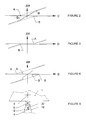
- the figure 2 shows the curve of the additional return moment generated by the blades as a function of the deflection angle of the balance relative to its rest position, that is to say the variation of the torque ⁇ M as a function of the deflection D.
- the dotted upper curve is relative to the blade 10
- the dotted lower curve is relative to the blade 9
- the solid line curve is relative to the combined effect of the two blades.
- the global curve versus deflection has a slope of 2. ⁇ K (K is the elastic constant of the global return spring) due to the action of two elastic strips 9 and 10 added to that of the spiral spring 3.
- K is the elastic constant of the global return spring
- the slope of the response curve is only ⁇ K, which corresponds to the fact that there is only one elastic blade (9 or 10) bearing on the abutment 8.
- the slope 2. ⁇ K is constant.
- the torque correction ⁇ M as a function of deflection is no longer linear and the average slope lies between 2. ⁇ K at small amplitudes and ⁇ K at large amplitudes.
- the useful area of correction is in the vicinity, but outside, of the interval A-B.
- E is 200,000 N / mm 2 (for steel)
- b is of the order of 0.5 mm
- L 8 mm
- R goal is 1 mm. It can therefore be deduced, using the preceding formulas, that the thickness h of the blade is of the order of 10 -5 m. Such a blade can be cut into a sheet 10 microns thick and folded to allow attachment.
- the figure 3 illustrates a variant of adjustment of the orientation of the elastic blades, in which the latter are positioned in such a way that they are not in contact with the stop when the balance is in the neutral position (deflection angle equal to zero) but contact for a deflection angle A or B. That is to say that ⁇ M is zero in the range between A and B and slope ⁇ M outside this range. Consequently, the frequency variation ⁇ f is the opposite of that described above and allows therefore to correct a negative dependence as a function of the driving torque.
- the correction device can operate with a single elastic blade.
- the overall curve (solid line) of the torque ⁇ M merges with one of the two dotted curves of the Figures 2 and 3 .
- the answer is asymmetrical, the correction operating only on a single alternation of the oscillation of the balance.
- the connecting member 8 is fixed, not on the rocker 1, but on an intermediate piece 19, T-shaped and serving as an anchor, whose horizontal bar 19a (on the figure) is the base of the elastic blades 6 and 7 and whose vertical bar 19b (in the figure) is mounted, free to oscillate, on the axis 2 of the balance 1.
- the spiral spring 3 is then fixed between the arm 1 a pendulum and the vertical bar 19b, which is subject, moreover, to the action of two return springs 21, acting in opposition.
- the provision of the figure 4 has the effect of reducing the angle of oscillation of the anchor 19 relative to that of the balance 1, which allows, on the one hand, to use more rigid blades and, on the other hand, to avoid excessive deformation and friction.
- the figure 5 shows yet another variant with a fixed stop 22 linked to the frame 4 facing the abutment 8 for a deflection angle of the balance 1 relative to its rest position equal to zero.
- This stop serves to connect and disconnect under prestressing the elastic blades 9 and 10 of the movable connecting member 8.
- an oscillator advantageously usable in a mechanical timepiece, which is provided with means for correcting the defect of isochronism induced by the variations of the engine torque.
- the correction performed is all the more effective as the amplitude-defect isochronism equilibrium is stable, which is the case of an elastic suspension balance such as, for example, that of the figure 5 of the document EP 1 736 838 , already quoted.
Landscapes
- Physics & Mathematics (AREA)
- General Physics & Mathematics (AREA)
- Springs (AREA)
- Inductance-Capacitance Distribution Constants And Capacitance-Resistance Oscillators (AREA)
Priority Applications (2)
| Application Number | Priority Date | Filing Date | Title |
|---|---|---|---|
| EP08101699A EP2090941B1 (de) | 2008-02-18 | 2008-02-18 | Mechanischer Oszillator |
| US12/372,091 US7963693B2 (en) | 2008-02-18 | 2009-02-17 | Mechanical oscillator |
Applications Claiming Priority (1)
| Application Number | Priority Date | Filing Date | Title |
|---|---|---|---|
| EP08101699A EP2090941B1 (de) | 2008-02-18 | 2008-02-18 | Mechanischer Oszillator |
Publications (2)
| Publication Number | Publication Date |
|---|---|
| EP2090941A1 true EP2090941A1 (de) | 2009-08-19 |
| EP2090941B1 EP2090941B1 (de) | 2011-10-19 |
Family
ID=39874166
Family Applications (1)
| Application Number | Title | Priority Date | Filing Date |
|---|---|---|---|
| EP08101699A Active EP2090941B1 (de) | 2008-02-18 | 2008-02-18 | Mechanischer Oszillator |
Country Status (2)
| Country | Link |
|---|---|
| US (1) | US7963693B2 (de) |
| EP (1) | EP2090941B1 (de) |
Cited By (7)
| Publication number | Priority date | Publication date | Assignee | Title |
|---|---|---|---|---|
| EP2911012A1 (de) * | 2014-02-20 | 2015-08-26 | CSEM Centre Suisse d'Electronique et de Microtechnique SA - Recherche et Développement | Oszillator einer Uhr |
| EP3076245A1 (de) | 2015-04-02 | 2016-10-05 | CSEM Centre Suisse D'electronique Et De Microtechnique SA | Dämpfungsvorrichtung, insbesondere für mikromechanische uhrkomponente |
| FR3048792A1 (fr) * | 2016-03-14 | 2017-09-15 | Lvmh Swiss Mft Sa | Dispositif pour piece d'horlogerie, mouvement horloger et piece d'horlogerie comprenant un tel dispositif |
| FR3048791A1 (fr) * | 2016-03-14 | 2017-09-15 | Lvmh Swiss Mft Sa | Mecanisme pour piece d'horlogerie et piece d'horlogerie comprenant un tel mecanisme |
| WO2017157870A1 (fr) * | 2016-03-14 | 2017-09-21 | Lvmh Swiss Manufactures Sa | Dispositif pour pièce d'horlogerie, mouvement horloger et pièce d'horlogerie comprenant un tel dispositif |
| EP3299905A1 (de) | 2016-09-27 | 2018-03-28 | CSEM Centre Suisse d'Electronique et de Microtechnique SA - Recherche et Développement | Mechanischer oszillator für ein uhrwerk |
| CN111344640A (zh) * | 2017-10-02 | 2020-06-26 | 爱彼钟表业制造有限公司 | 带有具有旋转重锤和共同返回力的谐波振荡器的钟表调校设备 |
Families Citing this family (8)
| Publication number | Priority date | Publication date | Assignee | Title |
|---|---|---|---|---|
| EP2105806B1 (de) * | 2008-03-27 | 2013-11-13 | Sowind S.A. | Hemmungsmechanismus |
| EP2290476B1 (de) * | 2009-08-18 | 2014-04-23 | CSEM Centre Suisse d'Electronique et de Microtechnique SA - Recherche et Développement | Isochronismuskorrektor für Uhrhemmungsmechanismus und mit einem solchen Korrektor ausgestatteter Hemmungsmechanismus |
| JP5914456B2 (ja) † | 2010-04-01 | 2016-05-11 | ロレックス・ソシエテ・アノニムRolex Sa | 歯車用固定装置 |
| CN104220941B (zh) * | 2012-03-29 | 2017-03-22 | 尼瓦洛克斯-法尔股份有限公司 | 具有无圆盘的摆轮的柔性擒纵机构 |
| JP5918438B2 (ja) * | 2012-03-29 | 2016-05-18 | ニヴァロックス−ファー ソシエテ アノニム | 可動フレームを備えた可撓性エスケープ機構 |
| US10365609B2 (en) * | 2014-01-13 | 2019-07-30 | Ecole Polytechnique Federale De Lausanne (Epfl) | Isotropic harmonic oscillator and associated time base without escapement or with simplified escapement |
| US10585398B2 (en) | 2014-01-13 | 2020-03-10 | Ecole Polytechnique Federale De Lausanne (Epfl) | General two degree of freedom isotropic harmonic oscillator and associated time base |
| US12265359B2 (en) | 2016-07-06 | 2025-04-01 | Ecole Polytechnique Federale De Lausanne (Epfl) | General 2 degree of freedom isotropic harmonic oscillator and associated time base without escapement or with simplified escapement |
Citations (2)
| Publication number | Priority date | Publication date | Assignee | Title |
|---|---|---|---|---|
| CH279954A (fr) * | 1947-08-28 | 1951-12-31 | Strafford Andrews George | Mécanisme d'horlogerie. |
| EP1736838A1 (de) | 2005-06-23 | 2006-12-27 | CSEM Centre Suisse d'Electronique et de Microtechnique S.A. - Recherche et Développement | Hemmung und Oszillator für Uhren |
Family Cites Families (2)
| Publication number | Priority date | Publication date | Assignee | Title |
|---|---|---|---|---|
| DE10160287A1 (de) * | 2001-12-07 | 2003-06-26 | Lange Uhren Gmbh | Tourbillon |
| FR2842313B1 (fr) * | 2002-07-12 | 2004-10-22 | Gideon Levingston | Oscilliateur mecanique (systeme balancier et ressort spiral) en materiaux permettant d'atteindre un niveau superieur de precision, applique a un mouvement d'horlogerie ou autre instrument de precision |
-
2008
- 2008-02-18 EP EP08101699A patent/EP2090941B1/de active Active
-
2009
- 2009-02-17 US US12/372,091 patent/US7963693B2/en not_active Expired - Fee Related
Patent Citations (2)
| Publication number | Priority date | Publication date | Assignee | Title |
|---|---|---|---|---|
| CH279954A (fr) * | 1947-08-28 | 1951-12-31 | Strafford Andrews George | Mécanisme d'horlogerie. |
| EP1736838A1 (de) | 2005-06-23 | 2006-12-27 | CSEM Centre Suisse d'Electronique et de Microtechnique S.A. - Recherche et Développement | Hemmung und Oszillator für Uhren |
Cited By (14)
| Publication number | Priority date | Publication date | Assignee | Title |
|---|---|---|---|---|
| EP2911012A1 (de) * | 2014-02-20 | 2015-08-26 | CSEM Centre Suisse d'Electronique et de Microtechnique SA - Recherche et Développement | Oszillator einer Uhr |
| US9207641B2 (en) | 2014-02-20 | 2015-12-08 | Csem Centre Suisse D'electronique Et De Microtechnique Sa—Recherche Et Developpement | Timepiece oscillator |
| EP3076245A1 (de) | 2015-04-02 | 2016-10-05 | CSEM Centre Suisse D'electronique Et De Microtechnique SA | Dämpfungsvorrichtung, insbesondere für mikromechanische uhrkomponente |
| US10452027B2 (en) | 2015-04-02 | 2019-10-22 | CSEM Centre Suisse d'Electronique et de Microtechnique SA—Recherche et Développement | Shock-absorber device, in particular for a micromechanical clockwork component |
| WO2017157868A1 (fr) * | 2016-03-14 | 2017-09-21 | Lvmh Swiss Manufactures Sa | Mécanisme pour pièce d'horlogerie et pièce d'horlogerie comprenant un tel mécanisme |
| WO2017157870A1 (fr) * | 2016-03-14 | 2017-09-21 | Lvmh Swiss Manufactures Sa | Dispositif pour pièce d'horlogerie, mouvement horloger et pièce d'horlogerie comprenant un tel dispositif |
| FR3048791A1 (fr) * | 2016-03-14 | 2017-09-15 | Lvmh Swiss Mft Sa | Mecanisme pour piece d'horlogerie et piece d'horlogerie comprenant un tel mecanisme |
| CN109478035A (zh) * | 2016-03-14 | 2019-03-15 | Lvmh瑞士制造公司 | 用于钟表的机构以及包括这种机构的钟表 |
| FR3048792A1 (fr) * | 2016-03-14 | 2017-09-15 | Lvmh Swiss Mft Sa | Dispositif pour piece d'horlogerie, mouvement horloger et piece d'horlogerie comprenant un tel dispositif |
| US11029649B2 (en) | 2016-03-14 | 2021-06-08 | LVHM Swiss Manufactures SA | Device for timepiece, clockwork movement and timepiece comprising such a device |
| US11460811B2 (en) | 2016-03-14 | 2022-10-04 | Lvmh Swiss Manufactures Sa | Mechanism for a timepiece and timepiece comprising such a mechanism |
| EP3299905A1 (de) | 2016-09-27 | 2018-03-28 | CSEM Centre Suisse d'Electronique et de Microtechnique SA - Recherche et Développement | Mechanischer oszillator für ein uhrwerk |
| US10317843B2 (en) | 2016-09-27 | 2019-06-11 | Csem Centre Suisse D'electronique Et De Microtechnique Sa—Recherche Et Developpement | Mechanical oscillator for a horological movement |
| CN111344640A (zh) * | 2017-10-02 | 2020-06-26 | 爱彼钟表业制造有限公司 | 带有具有旋转重锤和共同返回力的谐波振荡器的钟表调校设备 |
Also Published As
| Publication number | Publication date |
|---|---|
| EP2090941B1 (de) | 2011-10-19 |
| US7963693B2 (en) | 2011-06-21 |
| US20090207700A1 (en) | 2009-08-20 |
Similar Documents
| Publication | Publication Date | Title |
|---|---|---|
| EP2090941B1 (de) | Mechanischer Oszillator | |
| EP3059641B1 (de) | Oszillator mit einer chronometerhemmung | |
| EP2290476B1 (de) | Isochronismuskorrektor für Uhrhemmungsmechanismus und mit einem solchen Korrektor ausgestatteter Hemmungsmechanismus | |
| EP3545368A1 (de) | Rotierender resonator mit flexiblem führungssystem auf basis einer abgelösten ankerhemmung | |
| EP1605182B1 (de) | Unruh-Spiralfeder-Oszillator mit Temperaturkompensation | |
| EP1736838B1 (de) | Uhr | |
| EP2105806A1 (de) | Hemmungsmechanismus | |
| EP2297799B1 (de) | Autonome piezoelektrische anordnung zum erzeugen einer elektrischen spannung | |
| EP3037894B1 (de) | Mechanismus und Verfahren zur Geschwindigkeitseinstellung in einem Uhrwerk | |
| CH718113B1 (fr) | Ressort-spiral pour mécanisme résonateur d'horlogerie muni de moyens d'ajustement de la rigidité | |
| WO2015010797A1 (fr) | Resonateur de mouvement d'horlogerie et ensemble comprenant un tel resonateur et un mecanisme d'echappement | |
| CH716525B1 (fr) | Régulateur mécanique horloger auto-démarrant. | |
| EP2515185A1 (de) | Motor mit konstantem Drehmoment | |
| EP4357857A1 (de) | Spiralfeder für resonatormechanismus einer uhr mit mitteln zur einstellung der steifigkeit | |
| CH721873A2 (fr) | Mécanisme d'échappement muni de moyens d'ajustement de la marche et mouvement horloger le comprenant | |
| EP4715483A1 (de) | Uhrvorrichtung mit einer unruh-spiralfeder und einer gangeinstellvorrichtung | |
| EP4357858A1 (de) | Spiralfeder für resonatormechanismus einer uhr mit mitteln zur einstellung der steifigkeit | |
| CH681067A5 (de) | ||
| CH720139A2 (fr) | Ressort-spiral pour mécanisme résonateur d'horlogerie muni de moyens d'ajustement de la raideur. | |
| EP4575667A1 (de) | Halter für uhreinstellorgan mit mitteln zur gangeinstellung und/oder isochronismuseinstellung | |
| CH713837B1 (fr) | Dispositif de régulation sur la base d'un oscillateur harmonique isotrope pour pièce d'horlogerie. |
Legal Events
| Date | Code | Title | Description |
|---|---|---|---|
| PUAI | Public reference made under article 153(3) epc to a published international application that has entered the european phase |
Free format text: ORIGINAL CODE: 0009012 |
|
| AK | Designated contracting states |
Kind code of ref document: A1 Designated state(s): AT BE BG CH CY CZ DE DK EE ES FI FR GB GR HR HU IE IS IT LI LT LU LV MC MT NL NO PL PT RO SE SI SK TR |
|
| AX | Request for extension of the european patent |
Extension state: AL BA MK RS |
|
| 17P | Request for examination filed |
Effective date: 20100119 |
|
| AKX | Designation fees paid |
Designated state(s): CH DE FR GB LI |
|
| 17Q | First examination report despatched |
Effective date: 20100827 |
|
| GRAP | Despatch of communication of intention to grant a patent |
Free format text: ORIGINAL CODE: EPIDOSNIGR1 |
|
| GRAC | Information related to communication of intention to grant a patent modified |
Free format text: ORIGINAL CODE: EPIDOSCIGR1 |
|
| GRAJ | Information related to disapproval of communication of intention to grant by the applicant or resumption of examination proceedings by the epo deleted |
Free format text: ORIGINAL CODE: EPIDOSDIGR1 |
|
| GRAP | Despatch of communication of intention to grant a patent |
Free format text: ORIGINAL CODE: EPIDOSNIGR1 |
|
| GRAS | Grant fee paid |
Free format text: ORIGINAL CODE: EPIDOSNIGR3 |
|
| GRAA | (expected) grant |
Free format text: ORIGINAL CODE: 0009210 |
|
| AK | Designated contracting states |
Kind code of ref document: B1 Designated state(s): CH DE FR GB LI |
|
| REG | Reference to a national code |
Ref country code: GB Ref legal event code: FG4D Free format text: NOT ENGLISH |
|
| REG | Reference to a national code |
Ref country code: CH Ref legal event code: EP |
|
| REG | Reference to a national code |
Ref country code: CH Ref legal event code: NV Representative=s name: GLN S.A. |
|
| REG | Reference to a national code |
Ref country code: DE Ref legal event code: R096 Ref document number: 602008010543 Country of ref document: DE Effective date: 20120126 |
|
| PLBE | No opposition filed within time limit |
Free format text: ORIGINAL CODE: 0009261 |
|
| STAA | Information on the status of an ep patent application or granted ep patent |
Free format text: STATUS: NO OPPOSITION FILED WITHIN TIME LIMIT |
|
| 26N | No opposition filed |
Effective date: 20120720 |
|
| REG | Reference to a national code |
Ref country code: DE Ref legal event code: R097 Ref document number: 602008010543 Country of ref document: DE Effective date: 20120720 |
|
| REG | Reference to a national code |
Ref country code: CH Ref legal event code: PCAR Free format text: NEW ADDRESS: AVENUE EDOUARD-DUBOIS 20, 2000 NEUCHATEL (CH) |
|
| REG | Reference to a national code |
Ref country code: FR Ref legal event code: PLFP Year of fee payment: 9 |
|
| REG | Reference to a national code |
Ref country code: CH Ref legal event code: PFA Owner name: CSEM CENTRE SUISSE D'ELECTRONIQUE ET DE MICROT, CH Free format text: FORMER OWNER: CSEM CENTRE SUISSE D'ELECTRONIQUE ET DE MICROTECHNIQUE SA - RECHERCHE ET DEVELOPPEMENT, CH |
|
| REG | Reference to a national code |
Ref country code: FR Ref legal event code: PLFP Year of fee payment: 10 |
|
| REG | Reference to a national code |
Ref country code: FR Ref legal event code: PLFP Year of fee payment: 11 |
|
| REG | Reference to a national code |
Ref country code: CH Ref legal event code: NV Representative=s name: BOVARD SA NEUCHATEL CONSEILS EN PROPRIETE INTE, CH |
|
| PGFP | Annual fee paid to national office [announced via postgrant information from national office to epo] |
Ref country code: FR Payment date: 20210225 Year of fee payment: 14 |
|
| PGFP | Annual fee paid to national office [announced via postgrant information from national office to epo] |
Ref country code: DE Payment date: 20210323 Year of fee payment: 14 Ref country code: GB Payment date: 20210324 Year of fee payment: 14 |
|
| REG | Reference to a national code |
Ref country code: DE Ref legal event code: R119 Ref document number: 602008010543 Country of ref document: DE |
|
| GBPC | Gb: european patent ceased through non-payment of renewal fee |
Effective date: 20220218 |
|
| PG25 | Lapsed in a contracting state [announced via postgrant information from national office to epo] |
Ref country code: FR Free format text: LAPSE BECAUSE OF NON-PAYMENT OF DUE FEES Effective date: 20220228 |
|
| PG25 | Lapsed in a contracting state [announced via postgrant information from national office to epo] |
Ref country code: GB Free format text: LAPSE BECAUSE OF NON-PAYMENT OF DUE FEES Effective date: 20220218 Ref country code: DE Free format text: LAPSE BECAUSE OF NON-PAYMENT OF DUE FEES Effective date: 20220901 |
|
| PGFP | Annual fee paid to national office [announced via postgrant information from national office to epo] |
Ref country code: CH Payment date: 20250301 Year of fee payment: 18 |
|
| REG | Reference to a national code |
Ref country code: CH Ref legal event code: R18 Free format text: ST27 STATUS EVENT CODE: U-0-0-R10-R18 (AS PROVIDED BY THE NATIONAL OFFICE) Effective date: 20260209 |
|
| REG | Reference to a national code |
Ref country code: CH Ref legal event code: R18 Free format text: ST27 STATUS EVENT CODE: U-0-0-R10-R18 (AS PROVIDED BY THE NATIONAL OFFICE) Effective date: 20260320 |