EP2090948B1 - Procédé de fonctionnement d'un système d'automatisation - Google Patents
Procédé de fonctionnement d'un système d'automatisation Download PDFInfo
- Publication number
- EP2090948B1 EP2090948B1 EP08002958A EP08002958A EP2090948B1 EP 2090948 B1 EP2090948 B1 EP 2090948B1 EP 08002958 A EP08002958 A EP 08002958A EP 08002958 A EP08002958 A EP 08002958A EP 2090948 B1 EP2090948 B1 EP 2090948B1
- Authority
- EP
- European Patent Office
- Prior art keywords
- data
- domain controller
- automation
- configuration
- transmitted
- Prior art date
- Legal status (The legal status is an assumption and is not a legal conclusion. Google has not performed a legal analysis and makes no representation as to the accuracy of the status listed.)
- Ceased
Links
Images




Classifications
-
- G—PHYSICS
- G05—CONTROLLING; REGULATING
- G05B—CONTROL OR REGULATING SYSTEMS IN GENERAL; FUNCTIONAL ELEMENTS OF SUCH SYSTEMS; MONITORING OR TESTING ARRANGEMENTS FOR SUCH SYSTEMS OR ELEMENTS
- G05B19/00—Program-control systems
- G05B19/02—Program-control systems electric
- G05B19/04—Program control other than numerical control, i.e. in sequence controllers or logic controllers
- G05B19/042—Program control other than numerical control, i.e. in sequence controllers or logic controllers using digital processors
- G05B19/0426—Programming the control sequence
Definitions
- the invention relates to a method for operating an automation system with a plurality of communicatively connected Automatisieruhgsaki.
- Automation systems and automation devices combined therein are known per se.
- the Applicant delivers z.
- a programmable logic controller and a programming device for creating a control program for such a programmable logic controller known.
- Essential components of this programmable logic controller are modules for central tasks (CPU units) as well as signal, functional and communication modules.
- the CPU unit of the programmable logic controller cyclically executes a control program during the control operation, which a programmer creates with a software tool provided with a programming device and which is provided to solve an automation task.
- the CPU unit first reads the signal states at all physical process inputs and forms a process image of the inputs.
- the control program is processed step by step, including internal counters, markers and times, and finally the CPU unit stores the calculated signal states in the process image of the process outputs, from which these Signal states reach the physical process outputs.
- a control program usually includes software function blocks that enable operation of the signal and / or function and / or communication modules.
- One of these functional modules in the form of an NC control module can be used to control the technological sequence of movement of a processing machine.
- the CPU unit which usually implements process control functionalities, transmits parameters to this NC control module, e.g. B. parameters in the form of start / stop coordinates of the drive axes of the processing machine to be controlled.
- the CPU unit on the NC control board selects executable process programs that a processor of the NC control board processes to control the motion of a processing machine.
- automated device for the overall context of this description is to be interpreted as including all devices, devices or systems, ie in addition to z.
- controllers such as programmable logic controllers, process computers, (industrial) computers and the like, also drive controls, frequency converters and the like, as they are used to control, regulation and / or monitoring of technical processes z.
- B. for forming or transporting material, energy or information, etc. are used or can be used, in particular via suitable technical equipment such.
- sensors or actuators energy is spent or converted.
- large-scale systems as an example of a category of technical processes to be controlled or monitored, consist of individual, distributed projects which can also be called sub-processes, but whose data are of interest for working in the overall system or in the respective company.
- this includes, in particular, configuration data and runtime data, which are distributed across the various automation devices and are also partially redundantly stored. This leads to a large memory requirement and unnecessary data transfers, the latter in turn disadvantageously reduce the availability of each affected devices.
- many configuration data are typically the same across multiple projects in a plant, but also over multiple plants in a company / group or overlap in a wide range of areas (eg, user administration, facility maintenance, etc.).
- Simple central data storage of the configuration and runtime data creates problems, such as longer load times (eg by loading the data from a third-party device), lack of data availability due to network or device errors, etc., although the aspect of availability is just is of particular importance in the area of cross-plant data, that is, for company-wide access to the data.
- An object of the invention in the light of the above-outlined drawbacks, is to avoid them as far as possible or at least to reduce their effects.
- the automation system comprises a plurality of communicatively connected automation devices. Of the automation devices, exactly one acts as a domain controller and this device holds in a memory for the automation system and the automation equipment included centrally before the required for its or their operation data.
- the automation system includes a unit referred to as a "file transfer subsystem", which centrally receives data for updating individual option modules and, if necessary, maintains them.
- the domain controller holds as necessary for the operation of the automation system and the automation equipment includes required configuration and / or runtime data.
- the advantage of this embodiment is that the configuration and runtime data of the different Devices, projects or systems exclusively at a central point in the automation system, so the here and hereinafter referred to as a domain controller automation device, are stored.
- the domain controller is a defined device in the network comprised by the automation system for the communicative connection of the individual Automation devices. Data required for operation of the automation system and the automation devices comprised thereof, in particular runtime and configuration data, are stored exclusively on the domain controller. This also applies if access to the automation system with only temporarily connected automation devices, such.
- the domain controller performs a non-limited number of services that run independently and each manage a particular range of data, in particular configuration or runtime data, eg. B. Data for a user administration.
- This architecture ensures that the domain controller is not limited to powerful automation devices, such as As personal or industrial computers, but also on devices with limited resources, ie z. As control units or controllers, is executable. Ensuring the consistency of the data held by the domain controller is facilitated by central data management and data storage (instead of the previous distributed administration and storage). This means that all common data are stored on the domain controller and only individual device-specific data, ie data that is required only by a single device and does not require synchronization, are stored on the automation devices themselves. Apart from these data, no configuration or runtime data are stored on the automation devices comprised by the automation system or by control programs (clients) executed therefrom.
- a consistency check is comprised of a transfer of configuration or runtime data from a development system to the domain controller in such a way that first the respective data is transmitted to the domain controller and the domain controller acknowledges a transfer to the development system, then the development system initiates an activation of the transmitted data and the domain controller has a status resulting from the activation preparation to the development system and finally the development system, depending on the returned activation preparation status, enables the transmitted data for use.
- a consistency check is comprised of a transfer of configuration or runtime data from a development system to the domain controller in such a way that first the respective data is transmitted to the domain controller and the domain controller acknowledges a transfer to the development system, then the development system initiates an activation of the transmitted data and the domain controller has a status resulting from the activation preparation to the development system and finally the development system, depending on the returned activation preparation status, enables the transmitted data for use.
- transmitted data are enabled before their usability, it is ensured that no data still in the transfer, so z. Incomplete configuration or runtime data. Characterized in that an activation of transmitted data is initiated externally and in response to a resulting status, the unlocking, it is ensured that only properly transmitted data in the automation system for the automation equipment comprised thereof are used. After the activation of transmitted data, these are available at a central location and only once in the automation system for access by other automation devices comprised by the automation system.
- a scope of the buffering be dependent on a type of access, from a type of the accessing automation device and / or automatically selected by a structure of the accessed data.
- the caching takes place both on the accessing automation device or by the accessing automation device as well as on or by the supplying domain controller, because in this way a quasi interaction of the storage strategies available in each case is possible.
- the invention also relates to a computer program for carrying out such a method, comprising computer program instructions for implementing the individual method steps or method step sequences, a data carrier with such a computer program and a computer system on which such a computer program is loaded, ie, for. B. an automation device, which is provided for operation in an automation system of the type described here, in particular a domain controller.
- FIG. 1 shows a schematically simplified and generally designated 10 automation system with a plurality communicatively connected automation devices 12, 14, 16, 18, 20.
- the automation system 10 or the automation devices 12-20 thereof are in a conventional manner for the control and / or monitoring a technical process 22, not shown.
- the automation system 10 exchanges the technical process 22 in a manner known per se via sensors and actuators, not shown, process signals for receiving z.
- the communicative connection between the programmable controllers 12-20 is preferably via a bus 16, in particular a so-called fieldbus.
- a development system 26, 28 functioning programming devices or the like with the automation system 10 z. B. connectable by a connection to the bus 24 or to one of the programmable controllers 12-20.
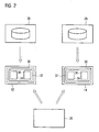
- FIG. 2 shows parts of the automation system 10 according to FIG. 1 in another representation. Shown are a first and a second automation device 12, 14, the z. To control individual ones of the technical process 22 (e.g. FIG. 1 ) are provided with independent or essentially independent sub-processes and can accordingly be regarded as the first and second systems. Each system, so each automation device 12, 14 or possibly also a combination of automation devices 12-20, holds in a memory 30 for operating the respective system required data 32.
- the data 32 includes in particular configuration and runtime data 34, 36. Such data 32 are entered and maintained with a development system 26, 28.
- the configuration and runtime data 34, 36 required for its operation an access to multiple programmable controllers 12-20, so z.
- parts of the data 32 are stored in a plurality of automation devices 12-20, an unnecessary allocation of memory 30 results.
- FIG. 3 shows essentially the same representation as FIG. 2 , but reduced to essential elements.
- the local storage of data 32 intended for operation of the programmable controllers 12-20 is omitted, and storage of such data 32 is instead provided on a special programmable controller 12-20, which is referred to below as a domain controller 38 for distinction.
- a domain controller 38 for distinction.
- the data 32 are supplied centrally by each development system 26, 28 provided for creating or modifying such data 32.
- each automation device 12 - 20 access to the data 32 can take place centrally at exactly one domain controller 38 encompassed by the automation system 10. This avoids multiple storage of the data 32 as well as unnecessary multiple data transfers.
- there is no need to reconcile data 32 as is the case with a constellation of data in FIG. 2 was still the case.
- FIG. 4 tries to illustrate the benefits associated with the invention in a graphical representation.
- a development system 26, 28, z. B a programming device, configuration and / or runtime data 34, 36 are provided and maintained for a plurality of programmable controllers 12-20.
- each automation device 12-20 locally holds the data required for its operation, in particular the configuration or runtime data 34, 36, in a respectively assigned memory.
- the approach according to the invention is shown.
- With the development system 26 12-20 required data, in particular configuration and runtime data 34, 36 are also created for the automation system 10 and the automation equipment comprised thereof groomed.
- the difference to the constellation shown on the left side is that the data required for the automation system 10 and the totality of the automation devices 12-20 thereof are centrally stored for the operation thereof, specifically in exactly one domain assigned to the automation system 10 Controller 38.
- the other automation devices 12-20 comprised by the automation system 10 such configuration and runtime data 34, 36 are stored locally at most, which are relevant exclusively to the respective automation device 12-20.
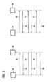
- FIG. 5 1 schematically shows, in simplified form, an aspect of a method for operating the automation system 10 (FIG. FIG. 1 ).
- the development system 26, 28 then initiates activation of the transmitted data by sending an activation signal 42.
- the domain controller 38 then returns a status resulting from the activation preparation in the form of a status signal 44 to the development system 26, 28.
- the initiation of the activation of the transmitted data comprises on the part of the domain controller 38, a complete verification of the transmitted data, ie z. For example, a plausibility check, a checksum test, etc.
- FIG. 5 presented to this process aspect a constellation in which z. B. an inconsistency of the configuration data 34 is detected, which is why as a status signal 44 an error signal is returned from the domain controller, whereupon the development system 26, 28 to the domain controller 38 sends a deletion request signal 50 and finally the domain controller 38 discards the transmitted data , The discarding of the data can be confirmed with an acknowledgment signal 48.
- FIG. 6 shows on the basis of FIG. 5 explained method, the designated execution of the domain controller 38.
- the memory 30 at least two memory areas 52, 54 are formed, which are referred to differentiate as a free memory area 52 and occupied memory area 54.
- the data 32 in particular configuration and runtime data 34, 36, required for its or their operation, are stored centrally in this automation device 10 and the automation devices 12-20 included therein.
- the first step when transferring data from a development system 26, 28 to the domain controller 38, they are transferred to the free memory area 52 without overwriting data 32 already present on the domain controller 38, that is, the data in the occupied memory area 54.
- a memory area 54 occupied by corresponding older data is marked as free for subsequent overwriting. If no final activation takes place in connection with the transfer of the data, the storage area occupied by the transferred data, that is to say the originally free storage area 52, is again marked as free for a later overwriting.
- a temporary storage takes place either on the domain controller 38 side or on the side of the respective automation device 12-20 requesting data from such access and / or caching data suspected to be requested in the near future with respect to the requested data.
- a scope of the intermediate storage can be selected automatically depending on a type of access, on a type of the respectively accessing automation device 12-20 and / or on a structure of the data accessed.
- a cache strategy based on a type of access that is, an access-specific cache strategy, is based on the realization that different accesses to e.g. B.
- configuration or runtime data 34, 36 (such as display in lists, reading of individual data or writing specific data) only specific portions of the configuration or runtime data 34, 36 need.
- a device-specific cache strategy is based on the fact that different devices 12-20 accessing the domain controller 38 can only access special configuration or runtime data due to the limitation of their respective resources, so that the cache mechanism only provides exactly the configuration or configuration adapted to the corresponding device. Runtime data 34, 36, so only a part of the total data holds.
- a structure-specific cache strategy dependent on a structure of the accessed data is based on the fact that, depending on the structure of the configuration or runtime data 34, 36, optimizations of the cache mechanism are possible. This means z.
- the cache loads structure data blocks whose size may be device-specific, whereas for structured data from a technological hierarchy (eg, objects such as pump station, etc.), associated substructures (e.g. B. pumps) are loaded to a predetermined or predetermined level, wherein such a depth with loaded or reloadable objects can also be device-specific again.
- Such intermediate storage can take place both on the part of the accessing automation device 12-20 and on the side of the domain controller 38.
- the domain controller 38 can be made highly available by using a redundant device. In the case of a redundant domain controller 38, both controllers run in a so-called "hot standby mode", which means that there is an active domain controller 38 (master) and a passive domain controller 38 (slave). The active domain controller 38 synchronizes all changes to the data 32 with the passive domain controller 38.
- the domain controller 38 Since the domain controller 38, the central management of the data 32, in particular the configuration or runtime data 34, 36, takes over, he provides via a Access layer the consistency of the data securely.
- the data access layer encapsulates the data 32 from the actual services and provides methods for creating, reading, writing, modifying, and deleting the data 32.
- the access layer automatically recognizes changes via its methods provided as an interface for accessing the data 32 Data 32 and notifies the cache affected by the changes. The or each cache affected so far accepts the changes and discards stored data depending on the selected cache strategy.
- the consistency of the data 32 is ensured via the access layer and a unique identifier for each development system 26, 28, ie, each development system 26, 28 guarantees the consistency of the data 32 influenced by them.
- the domain controller 38 centrally manages data 32, in particular configuration and runtime data 34, 36, of devices, projects and systems (plant-wide or company-wide) that are shared.
- the multiple duplication and loading of data 32 on each device is eliminated.
- the central technical aspects in the foreground first a structured (optimized) storage of the data 32 on the domain controller 38 for efficient and high-performance access, then a uniform cross-system management and addressing of data 32, the transparent access to this (project - or system-spanning), and finally an increase in the availability of the automation system 10 or devices 12-20 including devices by significant reduction of the volume of data to be transported.
Landscapes
- Physics & Mathematics (AREA)
- General Physics & Mathematics (AREA)
- Engineering & Computer Science (AREA)
- Automation & Control Theory (AREA)
- Programmable Controllers (AREA)
Claims (8)
- Procédé pour faire fonctionner un système d'automatisation, comprenant une multiplicité d'appareils (12 à 20 ) d'automatisation reliés en communication, dont l'un précisément fonctionne en domain-controller ( 38 ) et présente dans une mémoire ( 30 ), comme données nécessaires au fonctionnement du système ( 10 ) d'automatisation et aux appareils ( 12 à 20 ) d'automatisation qui l'englobent centralement des données ( 34 ) de configuration ou des données ( 36 ) de temps de fonctionnement,
caractérisé
en ce qu'un contrôle de conformité est englobé par un transfert de données ( 34, 36 ) de configuration ou de temps de fonctionnement d'un système ( 26, 28 ) de développement au domain-controller ( 38 ), de manière à ce que
les données respectives soient transmises d'abord au domain-controller ( 38 ) et à ce que le domain-controller ( 38 ) accuse réception au système ( 26, 28 ) de développement qu'une transmission a été effectuée,
puis une activation des données transmises est lancée par le système ( 26, 28 ) de développement et le domain-controller ( 38 ) refournit au système ( 26, 28 ) de développement un statut se produisant lors de la préparation de l'activation et enfin, le système ( 26, 28 ) de développement libère à l'utilisation les données transmises en fonction du statut de préparation de l'activation, qui a été fourni en retour. - Procédé suivant la revendication 1, dans lequel, dans le premier stade, lors de la transmission des données respectives au domain-controller ( 38 ), celles-ci sont transmises dans un domaine de mémoire libre du domain-controller ( 38 ), sans écrasement de données déjà présentes sur le domain-controller ( 38 ), dans lequel, lors de la libération des données transmises, un domaine de mémoire occupé par des données correspondantes plus anciennes est repéré comme libre pour un écrasement ultérieur, et dans lequel, lorsque, en relation avec la transmission, il ne s'effectue pas de libération ensuite le domaine de mémoire occupé par les données transmises est repéré comme libre pour un écrasement ultérieur.
- Procédé suivant la revendication 1 ou 2, dans lequel, lors de l'accès à des données présentées par le domain-controller ( 38 ), notamment des données ( 34, 36 ) de configuration et/ou de durée de fonctionnement, il s'effectue par un appareil ( 12 à 20 ) d'automatisation, soit du côté du domain-controller ( 38 ), soit du côté de l'appareil ( 12 à 20 ) d'automatisation, une mémorisation intermédiaire de données demandées par un accès de ce genre.
- Procédé suivant la revendication 3, dans lequel on choisit automatiquement une étendue de la mémorisation intermédiaire en fonction d'un type de l'accès d'un type de l'appareil ( 12 à 20 ) d'automatisation accédant respectivement et/ou d'une structure des données prises dans l'accès.
- Procédé suivant la revendication 3 et 4, dans lequel la mémorisation intermédiaire s'effectue à la fois sur l'appareil ( 12 à 20 ) d'automatisation accédant et sur le domain-controller ( 38 ) .
- Programme informatique, pour l'exécution d'un procédé suivant l'une des revendications 1 à 5.
- Support de données comprenant un programme informatique suivant la revendication 6.
- Système informatique, sur lequel un programme informatique, suivant la revendication 6, est chargé.
Priority Applications (3)
| Application Number | Priority Date | Filing Date | Title |
|---|---|---|---|
| DE502008001701T DE502008001701D1 (de) | 2008-02-18 | 2008-02-18 | Verfahren zum Betrieb eines Automatisierungssystems |
| EP08002958A EP2090948B1 (fr) | 2008-02-18 | 2008-02-18 | Procédé de fonctionnement d'un système d'automatisation |
| US12/378,575 US8095619B2 (en) | 2008-02-18 | 2009-02-17 | Automation system and method for operating such an automation system |
Applications Claiming Priority (1)
| Application Number | Priority Date | Filing Date | Title |
|---|---|---|---|
| EP08002958A EP2090948B1 (fr) | 2008-02-18 | 2008-02-18 | Procédé de fonctionnement d'un système d'automatisation |
Publications (2)
| Publication Number | Publication Date |
|---|---|
| EP2090948A1 EP2090948A1 (fr) | 2009-08-19 |
| EP2090948B1 true EP2090948B1 (fr) | 2010-11-03 |
Family
ID=39590742
Family Applications (1)
| Application Number | Title | Priority Date | Filing Date |
|---|---|---|---|
| EP08002958A Ceased EP2090948B1 (fr) | 2008-02-18 | 2008-02-18 | Procédé de fonctionnement d'un système d'automatisation |
Country Status (3)
| Country | Link |
|---|---|
| US (1) | US8095619B2 (fr) |
| EP (1) | EP2090948B1 (fr) |
| DE (1) | DE502008001701D1 (fr) |
Families Citing this family (4)
| Publication number | Priority date | Publication date | Assignee | Title |
|---|---|---|---|---|
| US11507947B1 (en) * | 2017-07-05 | 2022-11-22 | Citibank, N.A. | Systems and methods for data communication using a stateless application |
| US11768877B2 (en) * | 2019-09-20 | 2023-09-26 | Fisher-Rosemount Systems, Inc. | Smart search capabilities in a process control system |
| US11768878B2 (en) * | 2019-09-20 | 2023-09-26 | Fisher-Rosemount Systems, Inc. | Search results display in a process control system |
| WO2023245421A1 (fr) * | 2022-06-21 | 2023-12-28 | 宁德时代新能源科技股份有限公司 | Dispositif de commande de domaine, système de stockage d'énergie et procédé de commande pour système de stockage d'énergie |
Family Cites Families (7)
| Publication number | Priority date | Publication date | Assignee | Title |
|---|---|---|---|---|
| DE29617837U1 (de) | 1996-10-14 | 1997-11-13 | Siemens AG, 80333 München | Steuerung |
| US7139999B2 (en) * | 1999-08-31 | 2006-11-21 | Accenture Llp | Development architecture framework |
| US6704737B1 (en) * | 1999-10-18 | 2004-03-09 | Fisher-Rosemount Systems, Inc. | Accessing and updating a configuration database from distributed physical locations within a process control system |
| US6701345B1 (en) * | 2000-04-13 | 2004-03-02 | Accenture Llp | Providing a notification when a plurality of users are altering similar data in a health care solution environment |
| US20030061349A1 (en) * | 2001-09-24 | 2003-03-27 | George Lo | Method and system for collaboratively developing programming code for programmable controllers |
| CA2496165C (fr) * | 2002-08-19 | 2014-07-15 | Research In Motion Limited | Systeme et procede de commande securisee de ressources de dispositifs de communication mobiles sans fil |
| US7433968B2 (en) | 2003-03-12 | 2008-10-07 | Ge Fanuc Automation North America, Inc. | Methods and systems for management and control of an automation control module |
-
2008
- 2008-02-18 DE DE502008001701T patent/DE502008001701D1/de active Active
- 2008-02-18 EP EP08002958A patent/EP2090948B1/fr not_active Ceased
-
2009
- 2009-02-17 US US12/378,575 patent/US8095619B2/en not_active Expired - Fee Related
Also Published As
| Publication number | Publication date |
|---|---|
| DE502008001701D1 (de) | 2010-12-16 |
| EP2090948A1 (fr) | 2009-08-19 |
| US8095619B2 (en) | 2012-01-10 |
| US20090222106A1 (en) | 2009-09-03 |
Similar Documents
| Publication | Publication Date | Title |
|---|---|---|
| DE102009019088A1 (de) | Sicherheitssteuerung zum Steuern einer automatisierten Anlage und Verfahren zum Erstellen eines Anwenderprogramms für eine Sicherheitssteuerung | |
| DE10031670A1 (de) | Automatisch heruntergeladener verbindungsaktiver Plan | |
| EP1430369B1 (fr) | Acces dynamique a des ressources d'automatisation | |
| EP2407840A1 (fr) | Procédé pour faire fonctionner un dispositif d'automatisation | |
| DE102010002327A1 (de) | Controller und Steuerungssystem | |
| EP2732347B1 (fr) | Procédé et système de répartition dynamique de fonctions de programme dans des systèmes de commande répartis | |
| EP2090948B1 (fr) | Procédé de fonctionnement d'un système d'automatisation | |
| EP3444682A1 (fr) | Procédé d'accouplement assisté par ordinateur d'un module de traitement dans un système technique modulaire et système technique modulaire | |
| EP3082002B1 (fr) | Commande de securite et procede de commande d'une installation automatisee | |
| EP2557464B1 (fr) | Procédé destiné au fonctionnement d'un système d'automatisation | |
| EP2561415B1 (fr) | Procédé de gestion de données et commande à mémoire programmable | |
| DE10218816A1 (de) | Programmierbares Steuerungssystem | |
| DE112011105475B4 (de) | Programmierbare Logiksteuerung | |
| EP1536328B1 (fr) | Système de traitement de données avec la gestion automatisable et procédé pour la gestion automatisée d'un système de traitement de données | |
| EP3552063B1 (fr) | Procédé de configuration automatique d'unités fonctionnelles d'un système d'automatisation | |
| DE102008023873A1 (de) | Verfahren zum Betrieb eines Antriebssystems | |
| EP1454201B1 (fr) | Systeme d'ingenierie et systeme d'automatisation | |
| EP4390581A1 (fr) | Procédé et système d'ingénierie pour la conception et la programmation d'un agencement d'automatisation industriel doté d'un certain nombre de composants d'automatisation | |
| DE102006051188A1 (de) | Flexibles Verschaltungssystem | |
| EP1380908A2 (fr) | Système pour la configuration automatique de logiciel de commande | |
| EP1185910B1 (fr) | Procede de lancement synchronise d'une commande numerique | |
| DE102023111338B4 (de) | Netzwerk mit Kontrollfunktion für Netzwerkknoten | |
| EP2407841A2 (fr) | Procédé et système de mise en service ou d'actualisation d'une ou plusieurs machines issues de la technique d'automatisation | |
| WO2021037379A1 (fr) | Procédé pour faire fonctionner un groupe, noeud de travail de groupe, groupe, réseau, programme d'ordinateur et support lisible par ordinateur | |
| EP1217484A2 (fr) | Méthode et dispositif de traitement d'objets |
Legal Events
| Date | Code | Title | Description |
|---|---|---|---|
| PUAI | Public reference made under article 153(3) epc to a published international application that has entered the european phase |
Free format text: ORIGINAL CODE: 0009012 |
|
| 17P | Request for examination filed |
Effective date: 20090608 |
|
| AK | Designated contracting states |
Kind code of ref document: A1 Designated state(s): AT BE BG CH CY CZ DE DK EE ES FI FR GB GR HR HU IE IS IT LI LT LU LV MC MT NL NO PL PT RO SE SI SK TR |
|
| AX | Request for extension of the european patent |
Extension state: AL BA MK RS |
|
| GRAP | Despatch of communication of intention to grant a patent |
Free format text: ORIGINAL CODE: EPIDOSNIGR1 |
|
| RTI1 | Title (correction) |
Free format text: METHOD FOR OPERATING AN AUTOMATION SYSTEM |
|
| AKX | Designation fees paid |
Designated state(s): DE FR GB IT |
|
| GRAJ | Information related to disapproval of communication of intention to grant by the applicant or resumption of examination proceedings by the epo deleted |
Free format text: ORIGINAL CODE: EPIDOSDIGR1 |
|
| GRAP | Despatch of communication of intention to grant a patent |
Free format text: ORIGINAL CODE: EPIDOSNIGR1 |
|
| GRAS | Grant fee paid |
Free format text: ORIGINAL CODE: EPIDOSNIGR3 |
|
| GRAA | (expected) grant |
Free format text: ORIGINAL CODE: 0009210 |
|
| AK | Designated contracting states |
Kind code of ref document: B1 Designated state(s): DE FR GB IT |
|
| REG | Reference to a national code |
Ref country code: GB Ref legal event code: FG4D Free format text: NOT ENGLISH |
|
| REF | Corresponds to: |
Ref document number: 502008001701 Country of ref document: DE Date of ref document: 20101216 Kind code of ref document: P |
|
| PLBE | No opposition filed within time limit |
Free format text: ORIGINAL CODE: 0009261 |
|
| STAA | Information on the status of an ep patent application or granted ep patent |
Free format text: STATUS: NO OPPOSITION FILED WITHIN TIME LIMIT |
|
| 26N | No opposition filed |
Effective date: 20110804 |
|
| REG | Reference to a national code |
Ref country code: DE Ref legal event code: R097 Ref document number: 502008001701 Country of ref document: DE Effective date: 20110804 |
|
| REG | Reference to a national code |
Ref country code: FR Ref legal event code: PLFP Year of fee payment: 9 |
|
| REG | Reference to a national code |
Ref country code: FR Ref legal event code: PLFP Year of fee payment: 10 |
|
| REG | Reference to a national code |
Ref country code: FR Ref legal event code: PLFP Year of fee payment: 11 |
|
| PGFP | Annual fee paid to national office [announced via postgrant information from national office to epo] |
Ref country code: IT Payment date: 20190226 Year of fee payment: 12 Ref country code: GB Payment date: 20190213 Year of fee payment: 12 |
|
| PGFP | Annual fee paid to national office [announced via postgrant information from national office to epo] |
Ref country code: FR Payment date: 20190208 Year of fee payment: 12 |
|
| PGFP | Annual fee paid to national office [announced via postgrant information from national office to epo] |
Ref country code: DE Payment date: 20190416 Year of fee payment: 12 |
|
| REG | Reference to a national code |
Ref country code: DE Ref legal event code: R119 Ref document number: 502008001701 Country of ref document: DE |
|
| GBPC | Gb: european patent ceased through non-payment of renewal fee |
Effective date: 20200218 |
|
| PG25 | Lapsed in a contracting state [announced via postgrant information from national office to epo] |
Ref country code: FR Free format text: LAPSE BECAUSE OF NON-PAYMENT OF DUE FEES Effective date: 20200229 Ref country code: GB Free format text: LAPSE BECAUSE OF NON-PAYMENT OF DUE FEES Effective date: 20200218 Ref country code: DE Free format text: LAPSE BECAUSE OF NON-PAYMENT OF DUE FEES Effective date: 20200901 |
|
| PG25 | Lapsed in a contracting state [announced via postgrant information from national office to epo] |
Ref country code: IT Free format text: LAPSE BECAUSE OF NON-PAYMENT OF DUE FEES Effective date: 20200218 |