EP2091029A1 - Détection de danger incluant un dispositif de mesure de température intégré dans un microcontrôleur - Google Patents
Détection de danger incluant un dispositif de mesure de température intégré dans un microcontrôleur Download PDFInfo
- Publication number
- EP2091029A1 EP2091029A1 EP08101643A EP08101643A EP2091029A1 EP 2091029 A1 EP2091029 A1 EP 2091029A1 EP 08101643 A EP08101643 A EP 08101643A EP 08101643 A EP08101643 A EP 08101643A EP 2091029 A1 EP2091029 A1 EP 2091029A1
- Authority
- EP
- European Patent Office
- Prior art keywords
- temperature
- microcontroller
- measuring device
- measurement signal
- detector
- Prior art date
- Legal status (The legal status is an assumption and is not a legal conclusion. Google has not performed a legal analysis and makes no representation as to the accuracy of the status listed.)
- Granted
Links
Images

Classifications
-
- G—PHYSICS
- G08—SIGNALLING
- G08B—SIGNALLING SYSTEMS, e.g. PERSONAL CALLING SYSTEMS; ORDER TELEGRAPHS; ALARM SYSTEMS
- G08B17/00—Fire alarms; Alarms responsive to explosion
- G08B17/06—Electric actuation of the alarm, e.g. using a thermally-operated switch
-
- G—PHYSICS
- G08—SIGNALLING
- G08B—SIGNALLING SYSTEMS, e.g. PERSONAL CALLING SYSTEMS; ORDER TELEGRAPHS; ALARM SYSTEMS
- G08B17/00—Fire alarms; Alarms responsive to explosion
- G08B17/10—Actuation by presence of smoke or gases, e.g. automatic alarm devices for analysing flowing fluid materials by the use of optical means
- G08B17/103—Actuation by presence of smoke or gases, e.g. automatic alarm devices for analysing flowing fluid materials by the use of optical means using a light emitting and receiving device
- G08B17/107—Actuation by presence of smoke or gases, e.g. automatic alarm devices for analysing flowing fluid materials by the use of optical means using a light emitting and receiving device for detecting light-scattering due to smoke
-
- G—PHYSICS
- G08—SIGNALLING
- G08B—SIGNALLING SYSTEMS, e.g. PERSONAL CALLING SYSTEMS; ORDER TELEGRAPHS; ALARM SYSTEMS
- G08B17/00—Fire alarms; Alarms responsive to explosion
- G08B17/10—Actuation by presence of smoke or gases, e.g. automatic alarm devices for analysing flowing fluid materials by the use of optical means
- G08B17/11—Actuation by presence of smoke or gases, e.g. automatic alarm devices for analysing flowing fluid materials by the use of optical means using an ionisation chamber for detecting smoke or gas
- G08B17/113—Constructional details
-
- G—PHYSICS
- G08—SIGNALLING
- G08B—SIGNALLING SYSTEMS, e.g. PERSONAL CALLING SYSTEMS; ORDER TELEGRAPHS; ALARM SYSTEMS
- G08B29/00—Checking or monitoring of signalling or alarm systems; Prevention or correction of operating errors, e.g. preventing unauthorised operation
- G08B29/18—Prevention or correction of operating errors
- G08B29/20—Calibration, including self-calibrating arrangements
- G08B29/24—Self-calibration, e.g. compensating for environmental drift or ageing of components
Definitions
- the present invention relates to the technical field of danger detection technology.
- the present invention relates to a hazard detector which has a primary measuring device for detecting a physical measured quantity and for outputting a measuring signal which is indicative of a predefined dangerous situation, and a microcontroller, which is connected downstream of the measuring device and which is set up for evaluating the measuring signal.
- the present invention further relates to a method for detecting a dangerous situation.
- the present invention also relates to a computer-readable storage medium and to a program element which contain instructions for carrying out the method according to the invention for detecting a dangerous situation.
- Simple optical smoke detectors according to the scattered-light principle usually have a light emitting diode in the visible or in the infrared spectral range, which preferably emits light in a scattered range in pulsed form.
- the scattering area is often referred to as a labyrinth. If smoke particles are present in the scattering area, the light beams are at least partially scattered at these and detected by a correspondingly matched light receiver. The received optical power of the light receiver is decisive for the concentration of smoke particles.
- the danger detector is adjusted so that at a certain critical density of smoke particles an alarm is triggered.
- the so-called scattering angle between that emitted by the light emitting diode and that of the light receiver Detected measuring light is decisive, if, for example, rather smaller, darker particles, which arise in open fires, or rather larger, lighter particles, which arise in smoldering fires, are detected.
- a "forward scattering" smoke detector is to be understood as a smoke detector in which the angle between the measuring light emitted by the light-emitting diode and the measuring light detected by the light receiver is greater than 90 °, for example approximately 150 °.
- an optical fire detector with only one optical signal path and with an acceptable rate of false alarms usually responds very inhomogeneously to the various test fires.
- TF2 will fire an alarm very early, but the TF5 will fire an alarm very late.
- very early and “very late” always mean a time in relation to the time limits defined in standard 54-7.
- Additional sensor inputs may, for example, be coupled to a temperature sensor.
- the corresponding combination hazard detector is then called the "O-T" hazard alarm.
- O stands for optic and "T” for temperature.
- Such combination detectors are accordingly referred to as "O-O" hazard alarm.
- An "O-T” hazard detector has the disadvantage that its construction is relatively expensive. In fact, the cost of installing a temperature-sensitive component and of the temperature-sensitive component itself is incurred in the production of an "O-T" hazard alarm. In addition, the housing shape of the hazard detector must be adapted to the temperature-sensitive component and mechanical protection measures such as contact protection must be taken.
- the present invention is based on the device-related task of creating a low-cost but nevertheless false alarm-safe hazard alarm.
- the present invention is based on the method-related object to improve the detection of a dangerous situation with regard to a low false alarm rate in a cost-effective manner.
- a danger detector which may in particular be an optical smoke detector.
- the described danger detector has (a) a measuring device for detecting a physical measured variable and for outputting a measuring signal which are indicative of a given dangerous situation, (b) a microcontroller, which is connected downstream of the measuring device and which is set up to evaluate the measuring signal, and (c) a temperature measuring device for detecting a temperature and outputting a temperature measuring signal indicative of the detected temperature.
- the temperature measuring device is integrated in the microcontroller and the microcontroller is set up such that the temperature measurement signal is taken into account in the evaluation of the measurement signal.
- the danger alarm described is based on the finding that modern microprocessors often have integrated temperature-dependent components, which without or only can be used with a small additional apparatus design for a temperature measurement.
- the temperature measurement can be translated, for example by means of an analog / digital converter in a temperature value.
- This temperature value can then represent the housing temperature of the microcontroller.
- the heating of the housing of the microcontroller can be used in addition to the measurement signal of the measuring device as an additional hazard input for an alarm criterion of the danger detector.
- the temperature measuring device is integrated in the microcontroller. This means that a common component housing is provided for the microcontroller and the temperature measuring device. Typically, “integrated” further means that separation of the temperature measuring device from the microcontroller without destruction of at least one of the two components "microcontroller and temperature measuring device" is not possible.
- the sensitivity and response time of the temperature measuring device integrated in the microcontroller will generally not be as good as, for example, a separate temperature-sensitive resistor which is used in a known manner for special temperature detectors.
- Such temperature-sensitive resistors such as NTC resistors (negative temperature coefficient resistors) are in fact arranged spatially in a temperature detector so that they are optimally flowed by the ambient air and respond quickly due to a preferably low thermal mass. Thus, rapid temperature changes can be detected quickly.
- the temperature measuring device integrated in the microcontroller can not completely replace the NTC resistance of a thermal hazard alarm, so that, for example, the thermal standard EN54-5 relevant for danger detectors could not be met.
- One of the integrated temperature measuring device detected increase in the housing temperature of the microcontroller, however, can help to increase in a simple manner and in particular without additional equipment overhead both the sensitivity of the hazard alarm and to reduce the likelihood of triggering a false alarm.
- the temperature measuring signal of the temperature measuring device integrated in the microcontroller is thus used in addition to the measuring signal of the actual measuring device as a further or as an additional alarm signaling input.
- this additional alarm input is thus advantageously no additional apparatusiver effort required in the rule. This applies in any case for such microcontroller, which in any case have a suitable temperature measuring device.
- the measuring device can be, for example, a gas measuring device, which has a chemical sensor to which gas molecules from the ambient air on the sensor surface are chemically bound.
- the bound gas molecules can emit electrical charges which change the electrical conductance of the semiconductor material of the sensor.
- the gases to be detected can be combustion gases such as CO2. From a certain concentration in a monitored room then a danger message or an alarm message is generated by the described danger detector.
- the danger detector can of course also have a plurality of measuring devices, wherein at least one of the measuring devices is combined with the described temperature measuring device with regard to a common signal processing.
- the measurement signals provided by all measuring devices are preferably combined with one another.
- the temperature measuring device is a temperature measuring diode.
- the use of a temperature measuring diode as integrated into the microcontroller temperature measuring device has the advantage that it can be produced without additional process steps in a semiconductor manufacturing of the microcontroller.
- Temperature measuring diodes are already present in many modern microcontrollers anyway. Therefore, the danger detector described can be constructed with simple electronic standard components and thus realized in a cost effective manner.
- the measuring device is an optical measuring device, which has (a) a light transmitter, configured to emit a measuring light, and (b) a light receiver, configured to receive at least a part of the measuring light.
- O-T optical temperature
- the described danger detector works analogously to known so-called O-T (optical temperature) hazard detectors, whereby, however, a commonly used temperature-sensitive resistor is replaced by the temperature measuring device integrated in the microcontroller. This usually reduces the accuracy of the temperature measurement and slows down the time response to temperature changes.
- the temperature measurement signal can still be used for the evaluation of the measurement signal of the primary measuring device and thus contribute to a higher sensitivity and at the same time to a lower false alarm probability compared to hazard detectors with only a single measuring device.
- the described hazard alarm can be made significantly cheaper compared to known O-T hazard detectors.
- the temperature measuring device essentially increases the case temperature of the microcontroller detected. Even if the temperature measuring device is thus inevitably coupled with a comparatively large thermal mass, in the case of a fire the consideration of the rise in the housing temperature can contribute to fulfill the requirement for optical fire detector regulation EN54-7 even with a little sensitive optical balance and therefore the false alarm security significantly increase.
- the light receiver is preferably arranged at an angle of, for example, greater than 10 ° relative to the optical axis of the measurement light emitted by the light emitter. This means that only scattered measurement light reaches the light receiver, which generates a corresponding measurement signal in the presence of smoke particles.
- the light receiver is preferably arranged relative to the light transmitter so that at least a part of unscattered measurement light reaches the light receiver even when no smoke is present. The light intensity measured by the light receiver is in this case reduced by the presence of light-absorbing or even light-scattering smoke particles.
- the described primary optical hazard detector can be calibrated less sensitively compared to a known purely optical hazard alarm. This has the advantage that the matching process for the generation or the initiation of a danger message is considerably easier. This is because for more sensitive hazard detectors, the given tolerances are significantly narrower and thus such sensitive hazard detectors are much more difficult to manufacture within the narrow prescribed tolerances of the EN54-7 standard.
- the danger detector additionally has a detector housing in whose spatial center the microcontroller is arranged.
- This has the advantage that the thermal directional dependence of the described danger detector is low. This, in turn, means that a temperature change caused by a heat source can be detected with a constant sensitivity regardless of the direction in which the heat source is based on the described danger detector.
- the housing has a perfectly symmetrical shape.
- the microcontroller is then preferably arranged at the location within the housing, at which heat sources such as a fire can be detected as independent of direction as possible.
- the danger detector additionally has at least one heat-conducting element, which is connected to a housing of the microcontroller.
- the temperature measuring device of the microcontroller can better detect temperature changes in the air surrounding the danger detector.
- the good heat conducting materials and / or the at least one heat conducting element can be arranged such that they are flowed around or flowed against by the outside air of the hazard alarm.
- the heat-conducting element can also be referred to as a so-called thermal discharge pad.
- the described use of at least one heat conducting element has the advantage that a better thermal coupling the microcontroller to its environment and thus a shorter response time of the microcontroller housing to temperature changes can be ensured.
- the heat element can be used, for example, to thermally couple a shielding plate of the light emitting diode photodiode to the housing of the microcontroller. Since the Ableblleich the photodiode is typically within the air flowed through labyrinth or within the optical measuring chamber of the danger detector, the thermal coupling of the temperature measuring device is improved in a simple and efficient manner to the ambient air, thus effectively reducing the thermal time constant of the housing.
- a method for detecting a dangerous situation in particular for detecting smoke, is specified.
- the specified method comprises (a) detecting a physical measurand and outputting a measurement signal which are indicative of a given dangerous situation by means of a measuring device, (b) evaluating the measuring signal by means of a microcontroller which is connected downstream of the measuring device, and (c ) detecting a temperature and outputting a temperature measurement signal indicative of the detected temperature by means of a temperature measuring device.
- the temperature measuring device is integrated in the microcontroller.
- the temperature measurement signal is also taken into account in the evaluation of the measurement signal by the microcontroller.
- the specified method is based on the finding that simple danger detectors can be upgraded with only one sensor input in a simple manner and in particular without any additional equipment, since a temperature measuring device, which is already present in many modern microcontroller components, for a temperature measurement is used. A temperature measured value achieved thereby is taken into account in the evaluation of the primary measuring signal of the measuring device. Thus, a danger message initiated by the microcontroller no longer depends exclusively on the output primary measuring signal of the measuring device but also on the temperature measuring signal of the temperature measuring device integrated in the microcontroller.
- the method described has the advantage that it can be carried out without any apparatus conversions of many conventional hazard detectors. This also applies to hazard alarms, which initially have only a single alarm input or at least initially no thermal alarm input.
- hazard alarms which initially have only a single alarm input or at least initially no thermal alarm input.
- the only prerequisite for the implementation of the specified method is the presence of a microcontroller having an integrated temperature measuring device.
- the method described can be achieved by simple programming, i. be realized by software.
- the method additionally comprises amplifying the temporal changes of the measurement signal and / or the temperature measurement signal.
- amplifying the temporal changes of the measurement signal and / or the temperature measurement signal This means that, for example, in the case of a temperature increase, the increase in time of the temperature measurement curve detected by the temperature measuring device is increased. In other words, this means that the slope of the temperature measurement curve is increased.
- This can be done in a known manner, for example by a suitable software algorithm and / or by a suitably designed electronic circuit and thus in hardware.
- the described amplification of the temporal changes has the advantage that the temporal response of the integrated temperature measuring device, which is very much slowed down compared to an external NTC, after the Gain at least approximately to the response of an external temperature sensor, such as an NTC, can be approximated.
- only a relative change of the temperature measurement signal is taken into account in the evaluation of the measurement signal by the microcontroller.
- the production of the entire hazard alarm can be as fast as the production of a less powerful conventional hazard alarm, which has only one sensor input and possibly not used in a microcontroller temperature measuring device for the evaluation and initiate a danger message ,
- the temperature measurement signal is indicative of an absolute temperature.
- the consideration of a temperature measurement signal which is indicative of an absolute temperature value, has the advantage that not only temperature changes but also absolute temperature values can be taken into account in the evaluation of the primary measurement signal.
- the danger detector can be adapted even more specifically to specific environmental conditions and, on the one hand, high sensitivity and, on the other hand, a low false alarm probability of the danger detector can be achieved.
- the measuring device is an optical measuring device and the temperature measuring signal is used for a compensation of temperature-dependent effects of the optical measuring device.
- thermal effects within the entire temperature-dependent optical path can be compensated by means of the absolute temperature measurement signal.
- the term optical path is to be understood as meaning not only the entire optical path between the light emitter and the light receiver, but the optical path also includes optical or optoelectronic components, such as the light emitter and the light receiver.
- the optical path also includes optical or optoelectronic components, such as the light emitter and the light receiver.
- temperature changes not only the light output of the light emitter but also the sensitivity of the light receiver can change.
- a set relative adjustment between the light emitter and the light receiver for example, by thermal stresses of holding elements of the danger detector change. All these thermal effects can, insofar as reproducible and known in advance, be taken into account in the evaluation of the primary measurement signal and compensated in a suitable manner.
- the temperature measurement signal essentially reflects the housing temperature of the microcontroller.
- the housing temperature is used for temperature compensation of the optical path. This improves the response the danger detector especially at very cold and very hot temperatures.
- the response of the hazard alarm at 55 degrees may deviate by a maximum of a certain factor from the response at 25 degrees.
- the described compensation of temperature-dependent effects contributes to the fact that the corresponding optical measuring device can more easily fulfill the EN54-7 standard.
- a computer-readable storage medium in which a program for detecting a dangerous situation is stored.
- the program when executed by a microcontroller of a hazard alarm of the type described above, is arranged to perform the above-identified method of detecting a hazardous situation.
- a program element for detecting a dangerous situation is described.
- the program element when executed by a microcontroller of a hazard alarm of the type described above, is arranged to perform the above-identified method for detecting a hazardous situation.
- the program and / or program element may be implemented as a computer-readable instruction code in any suitable programming language such as JAVA, C ++, etc.
- the program and / or the program element can be stored on a computer-readable storage medium (CD-ROM, DVD, removable drive, volatile or non-volatile memory, built-in memory / processor, etc.).
- the instruction code may program a computer or other programmable device to perform the desired functions.
- the program and / or the program element in a network such as the Internet, from which it can be downloaded by a user as needed.
- the invention can be implemented both by means of a computer program, i. software, as well as by means of one or more special electrical circuits, i. in hardware or in any hybrid form, i. using software components and hardware components.
- FIG. 1 shows a schematic representation of a forward scattering, optical hazard detector 100.
- the upper part of FIG. 1 shows the danger detector 100 in a side view parallel to a mounting plane.
- the mounting plane can be, for example, the ceiling of a room to be monitored.
- the lower part of FIG. 1 shows the danger detector 100 in a plan view, wherein the viewing direction is oriented perpendicular to the mounting plane.
- the danger detector 100 has a primary optical measuring device, which is designed as a light emitting diode light emitter 110 and a photodiode formed as a light receiver 115.
- the optical measuring device operates according to the known scattered light principle. In this case, a measuring light is detected by the light receiver 115 in a known manner only when this measuring light is scattered on aerosols or smoke particles.
- the in FIG. 1 Hazard detector shown is thus a smoke detector 100, which is also suitable to detect fires.
- the light-emitting diode 110 is set up to emit measuring light in the infrared spectral range.
- the smoke detector 100 has a detector housing 140. Inside the housing 140 is a substrate 130 formed as a printed circuit board. Below the printed circuit board 130, an optical chamber 142 is formed by the detector housing 140, into which the smoke particles to be detected can enter via an air flow 150. In order to allow the most unobstructed air inlet, not shown air slots are formed in the detector housing 140.
- the smoke detector 100 further includes a microcontroller 120, which is coupled in a known manner with both the light emitter 110 and the light receiver 115.
- the microcontroller 120 is, on the one hand, for controlling the light-emitting diode 110, possibly via in FIG FIG. 1 not shown driver circuits set up. On the other hand, the microcontroller 120 is set up to evaluate an optical measurement signal generated by the photodiode 115.
- the microcontroller 120 has a temperature measuring device 125 designed as a temperature measuring diode.
- the temperature measuring diode 125 is integrated in the microcontroller 120. This means that the microcontroller 120 and the temperature measuring diode 125 are arranged in a common housing.
- the microcontroller 120 is set up, for example by suitable programming, such that a temperature measurement signal from the temperature measuring diode 125 is taken into account in the evaluation of a measurement signal generated by the photodiode 115.
- the described hazard alarm 100 differs from a known so-called O-T hazard alarm, inter alia, in that, instead of a separate temperature measuring resistor such as an NTC resistor, a temperature measuring device 125 integrated in the microcontroller 120 is used for the temperature measurement.
- the printed circuit board 130 is not only the electrical wiring or electrical contacting of electronic and optoelectronic components of the smoke detector 100. According to the embodiment shown here, the circuit board 130 also serves as a mechanical support for these components.
- heat conducting elements 134 are provided.
- the heat-conducting elements 134 which are also referred to as thermal pads, constitute a heat-conducting connection between the temperature measuring diode 125 and a heat exchange element 116.
- the heat-conducting connection is effected via a solder connection through a through-hole 132 to the heat exchange element 116
- the heat exchange element is a metallic shield 116 of the photodiode 115. As out FIG. 1 As can be seen, the metallic shield 116 flows against the ambient air 150 or flows around it, so that heating of the ambient air 150, in particular by an external source of fire, is rapidly detected by the integrated temperature measuring device 125.
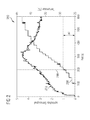
- FIG. 2 shows a diagram 260 in which the response of the in FIG. 1 illustrated optical hazard detector 100 for a test fire TF5 according to the standard EN54-7 is shown.
- Reference numeral 270 represents the optical measuring signal detected by the optical measuring device as a function of time. The time zero marks the beginning of the test fire TF5. The optical measurement signal 270 is displayed in relative units (see the ordinate on the left side of the diagram 260).
- Reference numeral 280 represents the temperature measuring signal detected by the temperature measuring device 125 as a function of time.
- the time axes of the optical measurement signal 270 and the temperature measurement signal 280 are identical.
- the temperature measurement signal 280 is represented in degrees Celsius (see the ordinate on the right side of the diagram 260).
- the measured temperature increase 280 lags behind the rise of the optical measuring signal 270 in terms of time. Nevertheless, the information provided by the temperature measurement signal 280 can be taken into account for the evaluation of the optical measurement signal 270. After all, the measured temperature increase .DELTA.T is already approximately 4 degrees Celsius 200 seconds after the start of the test fire TF5. By a combined evaluation of the optical measurement signal 270 and the temperature measurement signal 280, for example, the probability of triggering a false alarm with a still high reliability for the detection of an actual fire can be significantly reduced. This applies at least in comparison to a simple optical smoke detector with only one optical alarm input.
- the vertical line in the diagram 290 denoted by the reference numeral 290 represents the upper limit of the measured Test fire TF5 according to the EN54-7 standard. In the measured test fire shown, this limit is 200 seconds. If an alarm message is given at a later time, then in the case shown, the corresponding fire detector does not comply with the EN54-7 standard.
- the rise of the temperature measurement signal 280 can be initially amplified and only then used for a common signal evaluation. This means that the slope of the temperature measurement signal 280 is artificially increased. This can be done in a known manner, for example by a suitable software algorithm and / or by a suitably designed electronic circuit and thus in hardware.
- the increase of the optical measurement signal 270 can be amplified.
- the increased gain can also be used as an additional alarm criterion.
- the alarm time of the corresponding hazard alarm can be further reduced.
- the false alarming optical channel can be made even less sensitive.
Landscapes
- Physics & Mathematics (AREA)
- General Physics & Mathematics (AREA)
- Business, Economics & Management (AREA)
- Emergency Management (AREA)
- Chemical & Material Sciences (AREA)
- Analytical Chemistry (AREA)
- Engineering & Computer Science (AREA)
- Computer Security & Cryptography (AREA)
- Fire-Detection Mechanisms (AREA)
- Measuring And Recording Apparatus For Diagnosis (AREA)
- Measuring Temperature Or Quantity Of Heat (AREA)
- Testing Or Calibration Of Command Recording Devices (AREA)
Priority Applications (4)
| Application Number | Priority Date | Filing Date | Title |
|---|---|---|---|
| EP08101643.8A EP2091029B2 (fr) | 2008-02-15 | 2008-02-15 | Détection de danger incluant un dispositif de mesure de température intégré dans un microcontrôleur |
| AT08101643T ATE493724T1 (de) | 2008-02-15 | 2008-02-15 | Gefahrenerkennung mit einbezug einer in einem mikrocontroller integrierten temperaturmesseinrichtung |
| DE502008002126T DE502008002126D1 (de) | 2008-02-15 | 2008-02-15 | Gefahrenerkennung mit Einbezug einer in einem Mikrocontroller integrierten Temperaturmesseinrichtung |
| PCT/EP2009/051730 WO2009101187A1 (fr) | 2008-02-15 | 2009-02-13 | Détection de danger à l’aide d'un dispositif de mesure de la température intégré dans un microcontrôleur |
Applications Claiming Priority (1)
| Application Number | Priority Date | Filing Date | Title |
|---|---|---|---|
| EP08101643.8A EP2091029B2 (fr) | 2008-02-15 | 2008-02-15 | Détection de danger incluant un dispositif de mesure de température intégré dans un microcontrôleur |
Publications (3)
| Publication Number | Publication Date |
|---|---|
| EP2091029A1 true EP2091029A1 (fr) | 2009-08-19 |
| EP2091029B1 EP2091029B1 (fr) | 2010-12-29 |
| EP2091029B2 EP2091029B2 (fr) | 2020-11-18 |
Family
ID=39683670
Family Applications (1)
| Application Number | Title | Priority Date | Filing Date |
|---|---|---|---|
| EP08101643.8A Active EP2091029B2 (fr) | 2008-02-15 | 2008-02-15 | Détection de danger incluant un dispositif de mesure de température intégré dans un microcontrôleur |
Country Status (4)
| Country | Link |
|---|---|
| EP (1) | EP2091029B2 (fr) |
| AT (1) | ATE493724T1 (fr) |
| DE (1) | DE502008002126D1 (fr) |
| WO (1) | WO2009101187A1 (fr) |
Cited By (3)
| Publication number | Priority date | Publication date | Assignee | Title |
|---|---|---|---|---|
| WO2011128099A1 (fr) * | 2010-04-16 | 2011-10-20 | Winrich Hoseit | Dispositif de surveillance pour la surveillance d'un local |
| WO2011128100A1 (fr) * | 2010-04-16 | 2011-10-20 | Winrich Hoseit | Détecteur d'incendie pour la surveillance d'un local au moyen d'une combinaison de mesure de la densité de fumée et de la température |
| EP2463837A1 (fr) * | 2010-12-09 | 2012-06-13 | Nxp B.V. | Détecteur de fumée |
Citations (4)
| Publication number | Priority date | Publication date | Assignee | Title |
|---|---|---|---|---|
| EP0338218A1 (fr) * | 1988-03-30 | 1989-10-25 | Cerberus Ag | Méthode de détection précoce d'incendie |
| EP0618555A2 (fr) | 1993-03-31 | 1994-10-05 | Nohmi Bosai Ltd. | Avertisseur d'incendie équipé d'un détecteur de fumée |
| EP1103937A1 (fr) * | 1999-11-19 | 2001-05-30 | Siemens Building Technologies AG | Détecteur d'incendie |
| EP1253565A2 (fr) * | 2001-04-24 | 2002-10-30 | Matsushita Electric Works, Ltd. | Système d'alarme d'incendie |
Family Cites Families (7)
| Publication number | Priority date | Publication date | Assignee | Title |
|---|---|---|---|---|
| US5691704A (en) † | 1996-01-29 | 1997-11-25 | Engelhard Sensor Technologies, Inc. | Practical and improved fire detector |
| CH686913A5 (de) † | 1993-11-22 | 1996-07-31 | Cerberus Ag | Anordnung zur Frueherkennung von Braenden. |
| US5619430A (en) † | 1995-10-10 | 1997-04-08 | Microchip Technology Inc. | Microcontroller with on-chip linear temperature sensor |
| US6032109A (en) † | 1996-10-21 | 2000-02-29 | Telemonitor, Inc. | Smart sensor module |
| DE60010411T2 (de) † | 1999-11-05 | 2005-05-19 | E.I. Technology Ltd., Shannon | Rauchalarmvorrichtung |
| DE20219524U1 (de) † | 2002-12-17 | 2003-03-27 | Brecht, Thomas, 76646 Bruchsal | Akkumulator-Ladestation für Mobiltelefone mit integriertem Rauchgas-Meldesystem |
| DE102004024284A1 (de) † | 2003-07-17 | 2005-02-03 | Robert Bosch Gmbh | Verfahren und Vorrichtung zur Durchführung von Gefahrabwendungsmassnahmen für Lebewesen in Kraftfahrzeugen |
-
2008
- 2008-02-15 AT AT08101643T patent/ATE493724T1/de active
- 2008-02-15 DE DE502008002126T patent/DE502008002126D1/de active Active
- 2008-02-15 EP EP08101643.8A patent/EP2091029B2/fr active Active
-
2009
- 2009-02-13 WO PCT/EP2009/051730 patent/WO2009101187A1/fr not_active Ceased
Patent Citations (4)
| Publication number | Priority date | Publication date | Assignee | Title |
|---|---|---|---|---|
| EP0338218A1 (fr) * | 1988-03-30 | 1989-10-25 | Cerberus Ag | Méthode de détection précoce d'incendie |
| EP0618555A2 (fr) | 1993-03-31 | 1994-10-05 | Nohmi Bosai Ltd. | Avertisseur d'incendie équipé d'un détecteur de fumée |
| EP1103937A1 (fr) * | 1999-11-19 | 2001-05-30 | Siemens Building Technologies AG | Détecteur d'incendie |
| EP1253565A2 (fr) * | 2001-04-24 | 2002-10-30 | Matsushita Electric Works, Ltd. | Système d'alarme d'incendie |
Cited By (3)
| Publication number | Priority date | Publication date | Assignee | Title |
|---|---|---|---|---|
| WO2011128099A1 (fr) * | 2010-04-16 | 2011-10-20 | Winrich Hoseit | Dispositif de surveillance pour la surveillance d'un local |
| WO2011128100A1 (fr) * | 2010-04-16 | 2011-10-20 | Winrich Hoseit | Détecteur d'incendie pour la surveillance d'un local au moyen d'une combinaison de mesure de la densité de fumée et de la température |
| EP2463837A1 (fr) * | 2010-12-09 | 2012-06-13 | Nxp B.V. | Détecteur de fumée |
Also Published As
| Publication number | Publication date |
|---|---|
| WO2009101187A1 (fr) | 2009-08-20 |
| DE502008002126D1 (de) | 2011-02-10 |
| ATE493724T1 (de) | 2011-01-15 |
| EP2091029B1 (fr) | 2010-12-29 |
| EP2091029B2 (fr) | 2020-11-18 |
Similar Documents
| Publication | Publication Date | Title |
|---|---|---|
| DE102011119431C5 (de) | Streustrahlungsbrandmelder und Verfahren zur automatischen Erkennung einer Brandsituation | |
| US5497144A (en) | Testing and adjustment of scattered-light smoke detectors | |
| TWI654417B (zh) | 粒子偵測系統及相關方法 | |
| EP1709428B1 (fr) | Procede pour evaluer un signal de lumiere diffusee et detecteur de lumiere diffusee servant a la mise en oeuvre de ce procede | |
| EP1389331B1 (fr) | Systeme de detection d'incendie a auto-aspiration | |
| US5523744A (en) | Device for testing the operation of smoke detectors | |
| DE102004021663A1 (de) | Umgebungsbedingungsdetektor mit mehreren Sensoren und einer einzelnen Steuereinheit | |
| EP2091029B1 (fr) | Détection de danger incluant un dispositif de mesure de température intégré dans un microcontrôleur | |
| DE102012215212A1 (de) | Brandmeldevorrichtung zur Detektion und Meldung eines Brandes und Verfahren zur Funktionsprüfung der Brandmeldevorrichtung | |
| DE10353837B4 (de) | Prüfeinrichtung für Brandmelder | |
| DE102012201703A1 (de) | Automatischer Brandmelder zur Detektion von Bränden | |
| US11662302B2 (en) | Calibration of optical detector | |
| AU2015281304B2 (en) | Device and method for calibrating a scattered light meter | |
| EP4490477B1 (fr) | Système et procédé d'analyse de phénomènes induisant l'allumage | |
| EP3474249A2 (fr) | Dispositif de mesure destiné à la mesure de particules | |
| EP2759994B1 (fr) | Dispositif d'alerte d'incendie | |
| KR20220053654A (ko) | 레이저 유도 분광 시스템 및 방법 | |
| DE102006045055B3 (de) | Gasmeldeeinrichtung und Verfahren zum Überprüfen einer solchen | |
| EP0421100A1 (fr) | Procédé et dispositif pour reconnaître des conditions dangereuses dans une pièce | |
| DE102013208533A1 (de) | Brandmelder | |
| DE102004023524B3 (de) | Verfahren zur Erfassung und Meldung von Betauungen in Rauchmeldern | |
| DE10300848B4 (de) | Brandschalter für Lüftungsanlagen | |
| DE20121682U1 (de) | Selbstansaugende Brandmeldeeinrichtung | |
| EP2884033A1 (fr) | Protection anti-feu et son agencement | |
| DE102016216209A1 (de) | Optische Sensorvorrichtung und Verfahren zum Analysieren eines Analyten |
Legal Events
| Date | Code | Title | Description |
|---|---|---|---|
| PUAI | Public reference made under article 153(3) epc to a published international application that has entered the european phase |
Free format text: ORIGINAL CODE: 0009012 |
|
| AK | Designated contracting states |
Kind code of ref document: A1 Designated state(s): AT BE BG CH CY CZ DE DK EE ES FI FR GB GR HR HU IE IS IT LI LT LU LV MC MT NL NO PL PT RO SE SI SK TR |
|
| AX | Request for extension of the european patent |
Extension state: AL BA MK RS |
|
| 17P | Request for examination filed |
Effective date: 20100208 |
|
| 17Q | First examination report despatched |
Effective date: 20100310 |
|
| AKX | Designation fees paid |
Designated state(s): AT BE BG CH CY CZ DE DK EE ES FI FR GB GR HR HU IE IS IT LI LT LU LV MC MT NL NO PL PT RO SE SI SK TR |
|
| GRAP | Despatch of communication of intention to grant a patent |
Free format text: ORIGINAL CODE: EPIDOSNIGR1 |
|
| GRAS | Grant fee paid |
Free format text: ORIGINAL CODE: EPIDOSNIGR3 |
|
| GRAA | (expected) grant |
Free format text: ORIGINAL CODE: 0009210 |
|
| AK | Designated contracting states |
Kind code of ref document: B1 Designated state(s): AT BE BG CH CY CZ DE DK EE ES FI FR GB GR HR HU IE IS IT LI LT LU LV MC MT NL NO PL PT RO SE SI SK TR |
|
| REG | Reference to a national code |
Ref country code: GB Ref legal event code: FG4D Free format text: NOT ENGLISH |
|
| REG | Reference to a national code |
Ref country code: CH Ref legal event code: EP |
|
| REG | Reference to a national code |
Ref country code: IE Ref legal event code: FG4D Free format text: LANGUAGE OF EP DOCUMENT: GERMAN |
|
| REF | Corresponds to: |
Ref document number: 502008002126 Country of ref document: DE Date of ref document: 20110210 Kind code of ref document: P |
|
| REG | Reference to a national code |
Ref country code: DE Ref legal event code: R096 Ref document number: 502008002126 Country of ref document: DE Effective date: 20110210 |
|
| REG | Reference to a national code |
Ref country code: CH Ref legal event code: NV Representative=s name: SIEMENS SCHWEIZ AG |
|
| REG | Reference to a national code |
Ref country code: NL Ref legal event code: VDEP Effective date: 20101229 |
|
| PG25 | Lapsed in a contracting state [announced via postgrant information from national office to epo] |
Ref country code: LT Free format text: LAPSE BECAUSE OF FAILURE TO SUBMIT A TRANSLATION OF THE DESCRIPTION OR TO PAY THE FEE WITHIN THE PRESCRIBED TIME-LIMIT Effective date: 20101229 |
|
| LTIE | Lt: invalidation of european patent or patent extension |
Effective date: 20101229 |
|
| PG25 | Lapsed in a contracting state [announced via postgrant information from national office to epo] |
Ref country code: HR Free format text: LAPSE BECAUSE OF FAILURE TO SUBMIT A TRANSLATION OF THE DESCRIPTION OR TO PAY THE FEE WITHIN THE PRESCRIBED TIME-LIMIT Effective date: 20101229 Ref country code: LV Free format text: LAPSE BECAUSE OF FAILURE TO SUBMIT A TRANSLATION OF THE DESCRIPTION OR TO PAY THE FEE WITHIN THE PRESCRIBED TIME-LIMIT Effective date: 20101229 Ref country code: SI Free format text: LAPSE BECAUSE OF FAILURE TO SUBMIT A TRANSLATION OF THE DESCRIPTION OR TO PAY THE FEE WITHIN THE PRESCRIBED TIME-LIMIT Effective date: 20101229 Ref country code: BG Free format text: LAPSE BECAUSE OF FAILURE TO SUBMIT A TRANSLATION OF THE DESCRIPTION OR TO PAY THE FEE WITHIN THE PRESCRIBED TIME-LIMIT Effective date: 20110329 Ref country code: SE Free format text: LAPSE BECAUSE OF FAILURE TO SUBMIT A TRANSLATION OF THE DESCRIPTION OR TO PAY THE FEE WITHIN THE PRESCRIBED TIME-LIMIT Effective date: 20101229 Ref country code: CY Free format text: LAPSE BECAUSE OF FAILURE TO SUBMIT A TRANSLATION OF THE DESCRIPTION OR TO PAY THE FEE WITHIN THE PRESCRIBED TIME-LIMIT Effective date: 20101229 Ref country code: FI Free format text: LAPSE BECAUSE OF FAILURE TO SUBMIT A TRANSLATION OF THE DESCRIPTION OR TO PAY THE FEE WITHIN THE PRESCRIBED TIME-LIMIT Effective date: 20101229 |
|
| REG | Reference to a national code |
Ref country code: IE Ref legal event code: FD4D |
|
| PG25 | Lapsed in a contracting state [announced via postgrant information from national office to epo] |
Ref country code: IS Free format text: LAPSE BECAUSE OF FAILURE TO SUBMIT A TRANSLATION OF THE DESCRIPTION OR TO PAY THE FEE WITHIN THE PRESCRIBED TIME-LIMIT Effective date: 20110429 Ref country code: GR Free format text: LAPSE BECAUSE OF FAILURE TO SUBMIT A TRANSLATION OF THE DESCRIPTION OR TO PAY THE FEE WITHIN THE PRESCRIBED TIME-LIMIT Effective date: 20110330 Ref country code: PT Free format text: LAPSE BECAUSE OF FAILURE TO SUBMIT A TRANSLATION OF THE DESCRIPTION OR TO PAY THE FEE WITHIN THE PRESCRIBED TIME-LIMIT Effective date: 20110429 Ref country code: EE Free format text: LAPSE BECAUSE OF FAILURE TO SUBMIT A TRANSLATION OF THE DESCRIPTION OR TO PAY THE FEE WITHIN THE PRESCRIBED TIME-LIMIT Effective date: 20101229 Ref country code: NO Free format text: LAPSE BECAUSE OF FAILURE TO SUBMIT A TRANSLATION OF THE DESCRIPTION OR TO PAY THE FEE WITHIN THE PRESCRIBED TIME-LIMIT Effective date: 20110329 Ref country code: ES Free format text: LAPSE BECAUSE OF FAILURE TO SUBMIT A TRANSLATION OF THE DESCRIPTION OR TO PAY THE FEE WITHIN THE PRESCRIBED TIME-LIMIT Effective date: 20110409 Ref country code: CZ Free format text: LAPSE BECAUSE OF FAILURE TO SUBMIT A TRANSLATION OF THE DESCRIPTION OR TO PAY THE FEE WITHIN THE PRESCRIBED TIME-LIMIT Effective date: 20101229 |
|
| BERE | Be: lapsed |
Owner name: SIEMENS A.G. Effective date: 20110228 |
|
| PG25 | Lapsed in a contracting state [announced via postgrant information from national office to epo] |
Ref country code: PL Free format text: LAPSE BECAUSE OF FAILURE TO SUBMIT A TRANSLATION OF THE DESCRIPTION OR TO PAY THE FEE WITHIN THE PRESCRIBED TIME-LIMIT Effective date: 20101229 Ref country code: RO Free format text: LAPSE BECAUSE OF FAILURE TO SUBMIT A TRANSLATION OF THE DESCRIPTION OR TO PAY THE FEE WITHIN THE PRESCRIBED TIME-LIMIT Effective date: 20101229 Ref country code: SK Free format text: LAPSE BECAUSE OF FAILURE TO SUBMIT A TRANSLATION OF THE DESCRIPTION OR TO PAY THE FEE WITHIN THE PRESCRIBED TIME-LIMIT Effective date: 20101229 Ref country code: NL Free format text: LAPSE BECAUSE OF FAILURE TO SUBMIT A TRANSLATION OF THE DESCRIPTION OR TO PAY THE FEE WITHIN THE PRESCRIBED TIME-LIMIT Effective date: 20101229 |
|
| PG25 | Lapsed in a contracting state [announced via postgrant information from national office to epo] |
Ref country code: MC Free format text: LAPSE BECAUSE OF NON-PAYMENT OF DUE FEES Effective date: 20110228 |
|
| PLBI | Opposition filed |
Free format text: ORIGINAL CODE: 0009260 |
|
| PG25 | Lapsed in a contracting state [announced via postgrant information from national office to epo] |
Ref country code: DK Free format text: LAPSE BECAUSE OF FAILURE TO SUBMIT A TRANSLATION OF THE DESCRIPTION OR TO PAY THE FEE WITHIN THE PRESCRIBED TIME-LIMIT Effective date: 20101229 Ref country code: IE Free format text: LAPSE BECAUSE OF FAILURE TO SUBMIT A TRANSLATION OF THE DESCRIPTION OR TO PAY THE FEE WITHIN THE PRESCRIBED TIME-LIMIT Effective date: 20101229 |
|
| PLAX | Notice of opposition and request to file observation + time limit sent |
Free format text: ORIGINAL CODE: EPIDOSNOBS2 |
|
| 26 | Opposition filed |
Opponent name: HEKATRON VERTRIEBS GMBH Effective date: 20110929 |
|
| PG25 | Lapsed in a contracting state [announced via postgrant information from national office to epo] |
Ref country code: BE Free format text: LAPSE BECAUSE OF NON-PAYMENT OF DUE FEES Effective date: 20110228 |
|
| REG | Reference to a national code |
Ref country code: DE Ref legal event code: R026 Ref document number: 502008002126 Country of ref document: DE Effective date: 20110929 |
|
| PG25 | Lapsed in a contracting state [announced via postgrant information from national office to epo] |
Ref country code: MT Free format text: LAPSE BECAUSE OF FAILURE TO SUBMIT A TRANSLATION OF THE DESCRIPTION OR TO PAY THE FEE WITHIN THE PRESCRIBED TIME-LIMIT Effective date: 20101229 |
|
| PLBB | Reply of patent proprietor to notice(s) of opposition received |
Free format text: ORIGINAL CODE: EPIDOSNOBS3 |
|
| PG25 | Lapsed in a contracting state [announced via postgrant information from national office to epo] |
Ref country code: IT Free format text: LAPSE BECAUSE OF FAILURE TO SUBMIT A TRANSLATION OF THE DESCRIPTION OR TO PAY THE FEE WITHIN THE PRESCRIBED TIME-LIMIT Effective date: 20101229 |
|
| PLAB | Opposition data, opponent's data or that of the opponent's representative modified |
Free format text: ORIGINAL CODE: 0009299OPPO |
|
| RAP2 | Party data changed (patent owner data changed or rights of a patent transferred) |
Owner name: SIEMENS AKTIENGESELLSCHAFT |
|
| R26 | Opposition filed (corrected) |
Opponent name: HEKATRON VERTRIEBS GMBH Effective date: 20110929 |
|
| PG25 | Lapsed in a contracting state [announced via postgrant information from national office to epo] |
Ref country code: LU Free format text: LAPSE BECAUSE OF NON-PAYMENT OF DUE FEES Effective date: 20110215 |
|
| PG25 | Lapsed in a contracting state [announced via postgrant information from national office to epo] |
Ref country code: TR Free format text: LAPSE BECAUSE OF FAILURE TO SUBMIT A TRANSLATION OF THE DESCRIPTION OR TO PAY THE FEE WITHIN THE PRESCRIBED TIME-LIMIT Effective date: 20101229 |
|
| PG25 | Lapsed in a contracting state [announced via postgrant information from national office to epo] |
Ref country code: HU Free format text: LAPSE BECAUSE OF FAILURE TO SUBMIT A TRANSLATION OF THE DESCRIPTION OR TO PAY THE FEE WITHIN THE PRESCRIBED TIME-LIMIT Effective date: 20101229 |
|
| APBM | Appeal reference recorded |
Free format text: ORIGINAL CODE: EPIDOSNREFNO |
|
| APBP | Date of receipt of notice of appeal recorded |
Free format text: ORIGINAL CODE: EPIDOSNNOA2O |
|
| APAH | Appeal reference modified |
Free format text: ORIGINAL CODE: EPIDOSCREFNO |
|
| APBQ | Date of receipt of statement of grounds of appeal recorded |
Free format text: ORIGINAL CODE: EPIDOSNNOA3O |
|
| RAP2 | Party data changed (patent owner data changed or rights of a patent transferred) |
Owner name: SIEMENS SCHWEIZ AG |
|
| REG | Reference to a national code |
Ref country code: CH Ref legal event code: PUE Owner name: SIEMENS SCHWEIZ AG, CH Free format text: FORMER OWNER: SIEMENS AKTIENGESELLSCHAFT, DE |
|
| REG | Reference to a national code |
Ref country code: FR Ref legal event code: PLFP Year of fee payment: 8 |
|
| REG | Reference to a national code |
Ref country code: GB Ref legal event code: 732E Free format text: REGISTERED BETWEEN 20150220 AND 20150225 |
|
| REG | Reference to a national code |
Ref country code: AT Ref legal event code: PC Ref document number: 493724 Country of ref document: AT Kind code of ref document: T Owner name: SIEMENS SCHWEIZ AG, CH Effective date: 20150421 |
|
| REG | Reference to a national code |
Ref country code: DE Ref legal event code: R081 Ref document number: 502008002126 Country of ref document: DE Owner name: SIEMENS SCHWEIZ AG, CH Free format text: FORMER OWNER: SIEMENS AKTIENGESELLSCHAFT, 80333 MUENCHEN, DE |
|
| REG | Reference to a national code |
Ref country code: FR Ref legal event code: PLFP Year of fee payment: 9 |
|
| REG | Reference to a national code |
Ref country code: FR Ref legal event code: TP Owner name: SIEMENS SCHWEIZ AG, CH Effective date: 20160202 |
|
| REG | Reference to a national code |
Ref country code: FR Ref legal event code: PLFP Year of fee payment: 10 |
|
| REG | Reference to a national code |
Ref country code: FR Ref legal event code: PLFP Year of fee payment: 11 |
|
| APBU | Appeal procedure closed |
Free format text: ORIGINAL CODE: EPIDOSNNOA9O |
|
| PLAY | Examination report in opposition despatched + time limit |
Free format text: ORIGINAL CODE: EPIDOSNORE2 |
|
| POAG | Date of filing of petition for review recorded |
Free format text: ORIGINAL CODE: EPIDOSNPRV3 |
|
| POAH | Number of petition for review recorded |
Free format text: ORIGINAL CODE: EPIDOSNPRV1 |
|
| POAI | Petitioner in petition for review recorded |
Free format text: ORIGINAL CODE: EPIDOSNPRV2 |
|
| REG | Reference to a national code |
Ref country code: CH Ref legal event code: PK Free format text: BERICHTIGUNGEN |
|
| RIC2 | Information provided on ipc code assigned after grant |
Ipc: G08B 29/18 20060101ALI20191127BHEP Ipc: G08B 17/06 20060101AFI20191127BHEP Ipc: G08B 29/24 20060101ALI20191127BHEP Ipc: G08B 17/107 20060101ALI20191127BHEP Ipc: G08B 17/113 20060101ALI20191127BHEP |
|
| PUAH | Patent maintained in amended form |
Free format text: ORIGINAL CODE: 0009272 |
|
| STAA | Information on the status of an ep patent application or granted ep patent |
Free format text: STATUS: PATENT MAINTAINED AS AMENDED |
|
| REG | Reference to a national code |
Ref country code: CH Ref legal event code: AELC |
|
| 27A | Patent maintained in amended form |
Effective date: 20201118 |
|
| AK | Designated contracting states |
Kind code of ref document: B2 Designated state(s): AT BE BG CH CY CZ DE DK EE ES FI FR GB GR HR HU IE IS IT LI LT LU LV MC MT NL NO PL PT RO SE SI SK TR |
|
| REG | Reference to a national code |
Ref country code: DE Ref legal event code: R102 Ref document number: 502008002126 Country of ref document: DE |
|
| APBC | Information on closure of appeal procedure deleted |
Free format text: ORIGINAL CODE: EPIDOSDNOA9O |
|
| POAD | Information related to date of filing of petition for review deleted |
Free format text: ORIGINAL CODE: EPIDOSDPRV3 |
|
| POAK | Decision taken: petition for review obviously unsubstantiated |
Free format text: ORIGINAL CODE: 0009255 |
|
| PRVG | Petition for review allowed and appeal procedure re-opened |
Free format text: PETITION FOR REVIEW ALLOWED AND RE-OPENING OF THE APPEAL PROCEDURE WITH TOTAL REFUND OF THE FEE FOR THE PETITION FOR REVIEW Effective date: 20210315 |
|
| APBU | Appeal procedure closed |
Free format text: ORIGINAL CODE: EPIDOSNNOA9O |
|
| PUAD | Information related to the publication of a b2 document modified or deleted |
Free format text: ORIGINAL CODE: 0009399EPPU |
|
| D27A | Patent maintained in amended form (deleted) | ||
| DB2 | B2 document published (deleted) | ||
| PLAY | Examination report in opposition despatched + time limit |
Free format text: ORIGINAL CODE: EPIDOSNORE2 |
|
| P01 | Opt-out of the competence of the unified patent court (upc) registered |
Effective date: 20230523 |
|
| PLBC | Reply to examination report in opposition received |
Free format text: ORIGINAL CODE: EPIDOSNORE3 |
|
| APAH | Appeal reference modified |
Free format text: ORIGINAL CODE: EPIDOSCREFNO |
|
| APAW | Appeal reference deleted |
Free format text: ORIGINAL CODE: EPIDOSDREFNO |
|
| APBP | Date of receipt of notice of appeal recorded |
Free format text: ORIGINAL CODE: EPIDOSNNOA2O |
|
| APBQ | Date of receipt of statement of grounds of appeal recorded |
Free format text: ORIGINAL CODE: EPIDOSNNOA3O |
|
| REG | Reference to a national code |
Ref country code: DE Ref legal event code: R039 Ref document number: 502008002126 Country of ref document: DE Ref country code: DE Ref legal event code: R008 Ref document number: 502008002126 Country of ref document: DE |
|
| PGFP | Annual fee paid to national office [announced via postgrant information from national office to epo] |
Ref country code: GB Payment date: 20250305 Year of fee payment: 18 |
|
| PGFP | Annual fee paid to national office [announced via postgrant information from national office to epo] |
Ref country code: DE Payment date: 20250417 Year of fee payment: 18 |
|
| PGFP | Annual fee paid to national office [announced via postgrant information from national office to epo] |
Ref country code: CH Payment date: 20250512 Year of fee payment: 18 |
|
| REG | Reference to a national code |
Ref country code: DE Ref legal event code: R040 Ref document number: 502008002126 Country of ref document: DE |
|
| PGFP | Annual fee paid to national office [announced via postgrant information from national office to epo] |
Ref country code: AT Payment date: 20260116 Year of fee payment: 19 |
|
| PGFP | Annual fee paid to national office [announced via postgrant information from national office to epo] |
Ref country code: FR Payment date: 20260213 Year of fee payment: 19 |