EP2091110A2 - Connecteur à fiches électrique - Google Patents
Connecteur à fiches électrique Download PDFInfo
- Publication number
- EP2091110A2 EP2091110A2 EP20090001274 EP09001274A EP2091110A2 EP 2091110 A2 EP2091110 A2 EP 2091110A2 EP 20090001274 EP20090001274 EP 20090001274 EP 09001274 A EP09001274 A EP 09001274A EP 2091110 A2 EP2091110 A2 EP 2091110A2
- Authority
- EP
- European Patent Office
- Prior art keywords
- pair
- conductors
- conductor
- line pair
- wires
- Prior art date
- Legal status (The legal status is an assumption and is not a legal conclusion. Google has not performed a legal analysis and makes no representation as to the accuracy of the status listed.)
- Granted
Links
- 239000004020 conductor Substances 0.000 claims abstract description 141
- 239000003990 capacitor Substances 0.000 claims abstract description 24
- 230000008878 coupling Effects 0.000 claims description 2
- 238000010168 coupling process Methods 0.000 claims description 2
- 238000005859 coupling reaction Methods 0.000 claims description 2
- 230000015572 biosynthetic process Effects 0.000 claims 1
- 238000010586 diagram Methods 0.000 description 5
- 230000005540 biological transmission Effects 0.000 description 2
- 230000001419 dependent effect Effects 0.000 description 1
Images



Classifications
-
- H—ELECTRICITY
- H01—ELECTRIC ELEMENTS
- H01R—ELECTRICALLY-CONDUCTIVE CONNECTIONS; STRUCTURAL ASSOCIATIONS OF A PLURALITY OF MUTUALLY-INSULATED ELECTRICAL CONNECTING ELEMENTS; COUPLING DEVICES; CURRENT COLLECTORS
- H01R13/00—Details of coupling devices of the kinds covered by groups H01R12/70 or H01R24/00 - H01R33/00
- H01R13/646—Details of coupling devices of the kinds covered by groups H01R12/70 or H01R24/00 - H01R33/00 specially adapted for high-frequency, e.g. structures providing an impedance match or phase match
- H01R13/6461—Means for preventing cross-talk
- H01R13/6464—Means for preventing cross-talk by adding capacitive elements
-
- H—ELECTRICITY
- H01—ELECTRIC ELEMENTS
- H01R—ELECTRICALLY-CONDUCTIVE CONNECTIONS; STRUCTURAL ASSOCIATIONS OF A PLURALITY OF MUTUALLY-INSULATED ELECTRICAL CONNECTING ELEMENTS; COUPLING DEVICES; CURRENT COLLECTORS
- H01R13/00—Details of coupling devices of the kinds covered by groups H01R12/70 or H01R24/00 - H01R33/00
- H01R13/646—Details of coupling devices of the kinds covered by groups H01R12/70 or H01R24/00 - H01R33/00 specially adapted for high-frequency, e.g. structures providing an impedance match or phase match
- H01R13/6461—Means for preventing cross-talk
- H01R13/6467—Means for preventing cross-talk by cross-over of signal conductors
Definitions
- the invention relates to an electrical connector according to the preamble of claim 1.
- From the EP 0 558 225 B2 is an electrical connector with a housing and a housing positioned in the connector means known, wherein the connecting means comprises a plurality of substantially parallel electrical conductors forming an electrical conduction path between the input terminals and output terminals of the connecting means.
- the present invention is based on the problem of providing an improved with regard to the achievable minimization of near-end crosstalk electrical connector.
- an electrical connector is characterized in that a) between the first pair of wires and the second pair of lines Nahnebenschkompensation is constructed such that at least before the crossing of the conductor of the second pair of lines in the region of free ends thereof on the one hand between the leading conductor of the first pair of lines and a capacitance is connected to the return conductor of the second pair of wires and, on the other hand, a capacitance is connected between the return conductor of the first pair of wires and the outgoing conductor of the second pair of wires; b) between the first pair of wires and the third pair of wires a Nahnebenschitzpensation is constructed such that at least before the crossing of the conductor of the third pair of wires between the leading conductor of the first pair of lines and the leading conductor of the third pair of lines in the region of free ends thereof, a capacity and after the crossover of the conductors of the third pair of wires between the leading conductors of the first pair of wires and
- the present invention relates to an electrical connector, namely a data socket for contact receiving at least one data connector.
- the basic structure of such an electrical connector is known from the prior art, in particular EP 0 558 225 B2 , known.
- an electrical connector comprises a housing and a connecting device positioned in the housing, wherein the connecting device has a plurality of substantially parallel to each other, electrical conductors.
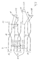
- Fig. 1 schematically shows an equivalent circuit diagram of an electrical connector according to the invention according to a first embodiment of the invention in the region of substantially parallel to each other extending electrical conductors of the housing positioned in the connecting device, wherein according to FIG Fig. 1 the connecting device comprises a total of eight electrical conductors 1, 2, 3, 4, 5, 6, 7 and 8.
- the electrical conductors 1 to 8 form an electrical conduction path between input terminals 9 and output terminals 10 of the connection device.
- the conductors 1 to 8 of the connector of Fig. 1 form a total of four pairs of lines, namely a first line pair 11, a second line pair 12, a third line pair 13 and a fourth line pair 14.
- the first line pair 11 is formed by the conductors 3 and 6, wherein it is the conductor 3 to the leading conductor and at the conductor 6 is about the returning conductor.
- the second line pair comprises the conductors 4 and 5, wherein the conductor 4 is the leading conductor and the conductor 5 is the returning conductor of the second pair of lines.
- the third line pair 13 comprises the conductors 1 and 2 and the fourth line pair 14, the conductors 7 and 8, wherein the conductors 2 and 8 respectively to the leading conductors and the conductors 1 and 7 respectively to the returning conductors of the corresponding line pairs 13, 14 acts.
- leading conductors 2, 3, 4, 8 are each marked with (+) and the returning conductors 1, 5, 6, 7 each with (-).
- Fig. 1 For example, some adjacent conductors 1 and 2, 4 and 5, and 7 and 8, the conductors of the second pair of leads 12, the third pair of leads 13 and the fourth pair 14, are crossed to minimize near-end crosstalk between the conductors without electrical contact therebetween the crossing of the conductors 4, 5 of the second line pair 12 by the reference numeral 15, the crossing of the electrical conductors 1, 2 of the third line pair 13 by the reference numeral 16 and the crossing of the conductors 7, 8 of the fourth line pair 14 by the reference numeral 17 are , By this crossover of the adjacent electrical conductors 1 and 2, 4 and 5 and 7 and 8, a Nahnebenschitzkompensation can already be realized to some extent.
- the conductors 3, 6 of the first line pair 11 are not crossed.
- a Nahnebenschitzkompensation constructed such that before the crossover 15 of the conductors 4 and 5 of the second line pair 12 in the region of free ends of the conductors 3, 4, 5 and 6, on the one hand between the running conductor 3 of First line pair 11 and the returning conductor 5 of the second line pair 12, a capacitor C35 and on the other hand between the returning conductor 6 of the first pair of lines and the leading conductor 4 of the second pair of lines 12, a capacitor C46 is connected.
- a Nahnebenschitzkompensation constructed such that before the crossover 16 of the conductors 1, 2 of the third line pair 13 between the leading conductor 3 of the first line pair 11 and the outgoing conductor 2 of the third line pair 13 in the region of free ends thereof a capacitor C23 and after the crossover 16 of the conductors 1, 2 of the third line pair 13 between the outgoing conductor 3 of the first pair of lines 11 and the returning conductor 1 of the third pair of lines 13, a capacitor C13 is connected.
- a Nahnebenschitzkompensation constructed such that before the crossover 17 of the conductors 7, 8 of the fourth line pair 14 between the leading conductor 3 of the first line pair 11 and the returning conductor 7 of the fourth Line pair 14 in the region of free ends thereof a capacitor C37 and after the crossing 17 of the conductors 7, 8 of the fourth line pair 14 between the return conductor 6 of the first pair of lines 11 and the returning conductor 7 of the fourth pair of lines 14, a capacitance C67 is connected.
- a multi-level compensation for near-end crosstalk is established between the first line pair 11 and the third line pair 13 and between the first line pair 11 and the fourth line pair 14.
- the capacitors C23, C13, C37 and C67 used for this purpose are preferably plate capacitors.
- the capacitances C35 and C46 which are connected between the conductors 3 and 5 or 4 and 6 of the first pair of leads 11 and the second pair of leads 12, are each preferably plate capacitors.
- the capacitances C13 and C67 which are positioned after the crossovers 16, 17 and thus in the region of the output terminals 10, are each connected via a branch line 18 to the corresponding conductors 1 and 3 or 6 and 7. Connecting the capacitances C13 and C67 via the stubs 18 to the corresponding electrical conductors serves to further reduce near-end crosstalk.
- Fig. 2 shows an advantageous development of the electrical connector of Fig. 1 Therefore, the same reference numerals are used to avoid unnecessary repetition for the same components below and in connection with Fig. 2 only the details will be described by which the embodiment of the Fig. 2 from the embodiment of Fig. 1 different.
- the Nahnebeneben pursuekompensation between the first pair of lines 11 and the second line pair 12 further developed in that after the crossover 15 of the electrical conductors 4 and 5 of the second line pair 12 and thus in the region of the output terminals 13 between the leading conductor 3 of the first pair of lines and the leading conductor. 4 of the second line pair, another capacitor, namely the capacitor CF34, is connected.
- the conductors 4 and 5 of the second pair of wires 12 are in each case coupling interdigital capacitors or so-called finger capacitors.
- These capacitors CF34 and CF56 are also connected via a branch line 18 to the corresponding electrical conductors 3 and 5 and 4 and 6 of the first pair of lines 11 and second pair of wires 12.
- FIG. 1 shows Fig. 3 , wherein also for the embodiment of Fig. 3 for identical components same reference numerals are used and only those details are described by which the embodiment of the Fig. 3 from the embodiment of Fig. 1 different.
- a capacitor C68 is connected, which is designed as a plate capacitor and is connected via a branch line 18 to the conductors 6, 8.
- a capacitor C25 connected, which in turn is designed as a plate capacitor and is connected via a branch line 18 to the conductors 2, 5.
- the further embodiment of the Fig. 4 is a combination of the embodiments Fig. 2 and 3 , the same therefore comprises both the capacitances CF34 and CF56 and the capacitances C25 and C68, in each case in the region of the output terminals 10.
- the inventive principle of an electrical connector can be used for any geometry of contact springs, which are part of the electrical conduction path of the electrical conductors.
Landscapes
- Details Of Connecting Devices For Male And Female Coupling (AREA)
Applications Claiming Priority (1)
| Application Number | Priority Date | Filing Date | Title |
|---|---|---|---|
| DE200820002209 DE202008002209U1 (de) | 2008-02-15 | 2008-02-15 | Elektrischer Steckverbinder |
Publications (3)
| Publication Number | Publication Date |
|---|---|
| EP2091110A2 true EP2091110A2 (fr) | 2009-08-19 |
| EP2091110A3 EP2091110A3 (fr) | 2013-12-04 |
| EP2091110B1 EP2091110B1 (fr) | 2015-10-21 |
Family
ID=39311751
Family Applications (1)
| Application Number | Title | Priority Date | Filing Date |
|---|---|---|---|
| EP09001274.1A Not-in-force EP2091110B1 (fr) | 2008-02-15 | 2009-01-30 | Connecteur à fiches électrique |
Country Status (2)
| Country | Link |
|---|---|
| EP (1) | EP2091110B1 (fr) |
| DE (1) | DE202008002209U1 (fr) |
Citations (1)
| Publication number | Priority date | Publication date | Assignee | Title |
|---|---|---|---|---|
| EP0558225B2 (fr) | 1992-02-24 | 2003-12-03 | AT&T Corp. | Fiche électrique modulaire à haute fréquence |
Family Cites Families (4)
| Publication number | Priority date | Publication date | Assignee | Title |
|---|---|---|---|---|
| US6371793B1 (en) * | 1998-08-24 | 2002-04-16 | Panduit Corp. | Low crosstalk modular communication connector |
| US6089923A (en) * | 1999-08-20 | 2000-07-18 | Adc Telecommunications, Inc. | Jack including crosstalk compensation for printed circuit board |
| US6964587B2 (en) * | 2002-11-10 | 2005-11-15 | Bel Fuse Ltd. | High performance, high capacitance gain, jack connector for data transmission or the like |
| US7190594B2 (en) * | 2004-05-14 | 2007-03-13 | Commscope Solutions Properties, Llc | Next high frequency improvement by using frequency dependent effective capacitance |
-
2008
- 2008-02-15 DE DE200820002209 patent/DE202008002209U1/de not_active Expired - Lifetime
-
2009
- 2009-01-30 EP EP09001274.1A patent/EP2091110B1/fr not_active Not-in-force
Patent Citations (1)
| Publication number | Priority date | Publication date | Assignee | Title |
|---|---|---|---|---|
| EP0558225B2 (fr) | 1992-02-24 | 2003-12-03 | AT&T Corp. | Fiche électrique modulaire à haute fréquence |
Also Published As
| Publication number | Publication date |
|---|---|
| EP2091110B1 (fr) | 2015-10-21 |
| DE202008002209U1 (de) | 2008-04-17 |
| EP2091110A3 (fr) | 2013-12-04 |
Similar Documents
| Publication | Publication Date | Title |
|---|---|---|
| DE69603184T2 (de) | Modularstecker für datenübertragung hoher geschwindigkeit | |
| DE102006056001B4 (de) | Konfektionierbarer Rundsteckverbinder für Ethernet | |
| EP1128491B1 (fr) | Elément de connecteur électrique | |
| EP2054978B1 (fr) | Système de raccordement | |
| DE102011001225A1 (de) | Anschlussvorrichtung und Anschlussverfahren für hochfrequente Digitalsignale | |
| WO2016008473A1 (fr) | Connecteur et composant | |
| DE69931230T2 (de) | Modularer Steckverbinder mit kapazitiven trennenden Platten | |
| EP2047571B1 (fr) | Connecteur enfichable pour les techniques de l'informatique et des télécommunications | |
| DE102007029125A1 (de) | Breitbandiger Richtkoppler mit einstellbarer Richtschärfe | |
| DE102009057260A1 (de) | Relief-Steckverbinder und Multilayerplatine | |
| DE102020115922A1 (de) | Steckverbinder und Steckverbinderadapter zur mehrfachen symmetrischen Signalübertragung | |
| DE20203910U1 (de) | Anschlussmodul der Telekommunikationstechnik | |
| EP1997194B1 (fr) | Connecteur pour la transmission de données et les télécommunications | |
| EP2091110B1 (fr) | Connecteur à fiches électrique | |
| EP3485540A1 (fr) | Adaptateur et câble muni de l'adaptateur | |
| DE2015445A1 (de) | Steckeranordnung mit Uberspannungsab leitern fur koaxiale Kabel und Leitungen, insbesondere fur Fernmeldezwecke | |
| EP3216089A1 (fr) | Interface électrique | |
| EP2081262A2 (fr) | Connecteur à fiche électrique | |
| DE7913680U1 (de) | Gesteuerter Leitungsanschlußblock | |
| EP0129820B1 (fr) | Elément de couplage pour le raccordement d'un appareil de transmission de signaux à une ligne principale coaxiale | |
| WO2001080443A1 (fr) | Agencement pour le transfert sans contact de signaux ou d'energie electriques entre plusieurs unites mobiles | |
| DE2949027C2 (de) | Hochfrequenz-Koppelfeld mit einem Gehäuse | |
| DE202011003115U1 (de) | Prüfanschlussvorrichtung für eine Datenbuchse | |
| WO2000076159A1 (fr) | Interface pour la separation de potentiel et pour la transmission de signaux numeriques | |
| DE102008009955A1 (de) | Einrichtung mit überkreuzter Streifenleitung |
Legal Events
| Date | Code | Title | Description |
|---|---|---|---|
| PUAI | Public reference made under article 153(3) epc to a published international application that has entered the european phase |
Free format text: ORIGINAL CODE: 0009012 |
|
| AK | Designated contracting states |
Kind code of ref document: A2 Designated state(s): AT BE BG CH CY CZ DE DK EE ES FI FR GB GR HR HU IE IS IT LI LT LU LV MC MK MT NL NO PL PT RO SE SI SK TR |
|
| AX | Request for extension of the european patent |
Extension state: AL BA RS |
|
| PUAL | Search report despatched |
Free format text: ORIGINAL CODE: 0009013 |
|
| AK | Designated contracting states |
Kind code of ref document: A3 Designated state(s): AT BE BG CH CY CZ DE DK EE ES FI FR GB GR HR HU IE IS IT LI LT LU LV MC MK MT NL NO PL PT RO SE SI SK TR |
|
| AX | Request for extension of the european patent |
Extension state: AL BA RS |
|
| RIC1 | Information provided on ipc code assigned before grant |
Ipc: H01R 13/6464 20110101AFI20131106BHEP |
|
| 17P | Request for examination filed |
Effective date: 20140604 |
|
| RBV | Designated contracting states (corrected) |
Designated state(s): AT BE BG CH CY CZ DE DK EE ES FI FR GB GR HR HU IE IS IT LI LT LU LV MC MK MT NL NO PL PT RO SE SI SK TR |
|
| AKX | Designation fees paid |
Designated state(s): AT BE BG CH CY CZ DE DK EE ES FI FR GB GR HR HU IE IS IT LI LT LU LV MC MK MT NL NO PL PT RO SE SI SK TR |
|
| REG | Reference to a national code |
Ref country code: DE Ref legal event code: R079 Ref document number: 502009011731 Country of ref document: DE Free format text: PREVIOUS MAIN CLASS: H01R0024040000 Ipc: H01R0013646400 |
|
| RIC1 | Information provided on ipc code assigned before grant |
Ipc: H01R 13/6467 20110101ALI20150401BHEP Ipc: H01R 13/6464 20110101AFI20150401BHEP |
|
| GRAP | Despatch of communication of intention to grant a patent |
Free format text: ORIGINAL CODE: EPIDOSNIGR1 |
|
| INTG | Intention to grant announced |
Effective date: 20150512 |
|
| RAP1 | Party data changed (applicant data changed or rights of an application transferred) |
Owner name: CCS TECHNOLOGY, INC. |
|
| GRAS | Grant fee paid |
Free format text: ORIGINAL CODE: EPIDOSNIGR3 |
|
| GRAA | (expected) grant |
Free format text: ORIGINAL CODE: 0009210 |
|
| AK | Designated contracting states |
Kind code of ref document: B1 Designated state(s): AT BE BG CH CY CZ DE DK EE ES FI FR GB GR HR HU IE IS IT LI LT LU LV MC MK MT NL NO PL PT RO SE SI SK TR |
|
| REG | Reference to a national code |
Ref country code: GB Ref legal event code: FG4D Free format text: NOT ENGLISH Ref country code: NL Ref legal event code: MP Effective date: 20151021 |
|
| REG | Reference to a national code |
Ref country code: CH Ref legal event code: EP |
|
| REG | Reference to a national code |
Ref country code: AT Ref legal event code: REF Ref document number: 757139 Country of ref document: AT Kind code of ref document: T Effective date: 20151115 |
|
| REG | Reference to a national code |
Ref country code: IE Ref legal event code: FG4D Free format text: LANGUAGE OF EP DOCUMENT: GERMAN |
|
| REG | Reference to a national code |
Ref country code: DE Ref legal event code: R096 Ref document number: 502009011731 Country of ref document: DE |
|
| REG | Reference to a national code |
Ref country code: LT Ref legal event code: MG4D |
|
| PG25 | Lapsed in a contracting state [announced via postgrant information from national office to epo] |
Ref country code: ES Free format text: LAPSE BECAUSE OF FAILURE TO SUBMIT A TRANSLATION OF THE DESCRIPTION OR TO PAY THE FEE WITHIN THE PRESCRIBED TIME-LIMIT Effective date: 20151021 Ref country code: NO Free format text: LAPSE BECAUSE OF FAILURE TO SUBMIT A TRANSLATION OF THE DESCRIPTION OR TO PAY THE FEE WITHIN THE PRESCRIBED TIME-LIMIT Effective date: 20160121 Ref country code: IT Free format text: LAPSE BECAUSE OF FAILURE TO SUBMIT A TRANSLATION OF THE DESCRIPTION OR TO PAY THE FEE WITHIN THE PRESCRIBED TIME-LIMIT Effective date: 20151021 Ref country code: IS Free format text: LAPSE BECAUSE OF FAILURE TO SUBMIT A TRANSLATION OF THE DESCRIPTION OR TO PAY THE FEE WITHIN THE PRESCRIBED TIME-LIMIT Effective date: 20160221 Ref country code: NL Free format text: LAPSE BECAUSE OF FAILURE TO SUBMIT A TRANSLATION OF THE DESCRIPTION OR TO PAY THE FEE WITHIN THE PRESCRIBED TIME-LIMIT Effective date: 20151021 Ref country code: HR Free format text: LAPSE BECAUSE OF FAILURE TO SUBMIT A TRANSLATION OF THE DESCRIPTION OR TO PAY THE FEE WITHIN THE PRESCRIBED TIME-LIMIT Effective date: 20151021 Ref country code: LT Free format text: LAPSE BECAUSE OF FAILURE TO SUBMIT A TRANSLATION OF THE DESCRIPTION OR TO PAY THE FEE WITHIN THE PRESCRIBED TIME-LIMIT Effective date: 20151021 |
|
| PG25 | Lapsed in a contracting state [announced via postgrant information from national office to epo] |
Ref country code: PL Free format text: LAPSE BECAUSE OF FAILURE TO SUBMIT A TRANSLATION OF THE DESCRIPTION OR TO PAY THE FEE WITHIN THE PRESCRIBED TIME-LIMIT Effective date: 20151021 Ref country code: GR Free format text: LAPSE BECAUSE OF FAILURE TO SUBMIT A TRANSLATION OF THE DESCRIPTION OR TO PAY THE FEE WITHIN THE PRESCRIBED TIME-LIMIT Effective date: 20160122 Ref country code: SE Free format text: LAPSE BECAUSE OF FAILURE TO SUBMIT A TRANSLATION OF THE DESCRIPTION OR TO PAY THE FEE WITHIN THE PRESCRIBED TIME-LIMIT Effective date: 20151021 Ref country code: FI Free format text: LAPSE BECAUSE OF FAILURE TO SUBMIT A TRANSLATION OF THE DESCRIPTION OR TO PAY THE FEE WITHIN THE PRESCRIBED TIME-LIMIT Effective date: 20151021 Ref country code: BE Free format text: LAPSE BECAUSE OF NON-PAYMENT OF DUE FEES Effective date: 20160131 Ref country code: LV Free format text: LAPSE BECAUSE OF FAILURE TO SUBMIT A TRANSLATION OF THE DESCRIPTION OR TO PAY THE FEE WITHIN THE PRESCRIBED TIME-LIMIT Effective date: 20151021 Ref country code: PT Free format text: LAPSE BECAUSE OF FAILURE TO SUBMIT A TRANSLATION OF THE DESCRIPTION OR TO PAY THE FEE WITHIN THE PRESCRIBED TIME-LIMIT Effective date: 20160222 |
|
| REG | Reference to a national code |
Ref country code: DE Ref legal event code: R097 Ref document number: 502009011731 Country of ref document: DE |
|
| PG25 | Lapsed in a contracting state [announced via postgrant information from national office to epo] |
Ref country code: CZ Free format text: LAPSE BECAUSE OF FAILURE TO SUBMIT A TRANSLATION OF THE DESCRIPTION OR TO PAY THE FEE WITHIN THE PRESCRIBED TIME-LIMIT Effective date: 20151021 |
|
| PLBE | No opposition filed within time limit |
Free format text: ORIGINAL CODE: 0009261 |
|
| STAA | Information on the status of an ep patent application or granted ep patent |
Free format text: STATUS: NO OPPOSITION FILED WITHIN TIME LIMIT |
|
| PG25 | Lapsed in a contracting state [announced via postgrant information from national office to epo] |
Ref country code: LU Free format text: LAPSE BECAUSE OF FAILURE TO SUBMIT A TRANSLATION OF THE DESCRIPTION OR TO PAY THE FEE WITHIN THE PRESCRIBED TIME-LIMIT Effective date: 20160130 Ref country code: DK Free format text: LAPSE BECAUSE OF FAILURE TO SUBMIT A TRANSLATION OF THE DESCRIPTION OR TO PAY THE FEE WITHIN THE PRESCRIBED TIME-LIMIT Effective date: 20151021 Ref country code: EE Free format text: LAPSE BECAUSE OF FAILURE TO SUBMIT A TRANSLATION OF THE DESCRIPTION OR TO PAY THE FEE WITHIN THE PRESCRIBED TIME-LIMIT Effective date: 20151021 Ref country code: SK Free format text: LAPSE BECAUSE OF FAILURE TO SUBMIT A TRANSLATION OF THE DESCRIPTION OR TO PAY THE FEE WITHIN THE PRESCRIBED TIME-LIMIT Effective date: 20151021 Ref country code: RO Free format text: LAPSE BECAUSE OF FAILURE TO SUBMIT A TRANSLATION OF THE DESCRIPTION OR TO PAY THE FEE WITHIN THE PRESCRIBED TIME-LIMIT Effective date: 20151021 |
|
| REG | Reference to a national code |
Ref country code: CH Ref legal event code: PL |
|
| 26N | No opposition filed |
Effective date: 20160722 |
|
| GBPC | Gb: european patent ceased through non-payment of renewal fee |
Effective date: 20160130 |
|
| PG25 | Lapsed in a contracting state [announced via postgrant information from national office to epo] |
Ref country code: MC Free format text: LAPSE BECAUSE OF FAILURE TO SUBMIT A TRANSLATION OF THE DESCRIPTION OR TO PAY THE FEE WITHIN THE PRESCRIBED TIME-LIMIT Effective date: 20151021 |
|
| REG | Reference to a national code |
Ref country code: FR Ref legal event code: ST Effective date: 20160930 |
|
| PG25 | Lapsed in a contracting state [announced via postgrant information from national office to epo] |
Ref country code: GB Free format text: LAPSE BECAUSE OF NON-PAYMENT OF DUE FEES Effective date: 20160130 Ref country code: LI Free format text: LAPSE BECAUSE OF NON-PAYMENT OF DUE FEES Effective date: 20160131 Ref country code: CH Free format text: LAPSE BECAUSE OF NON-PAYMENT OF DUE FEES Effective date: 20160131 |
|
| REG | Reference to a national code |
Ref country code: IE Ref legal event code: MM4A |
|
| PG25 | Lapsed in a contracting state [announced via postgrant information from national office to epo] |
Ref country code: SI Free format text: LAPSE BECAUSE OF FAILURE TO SUBMIT A TRANSLATION OF THE DESCRIPTION OR TO PAY THE FEE WITHIN THE PRESCRIBED TIME-LIMIT Effective date: 20151021 Ref country code: FR Free format text: LAPSE BECAUSE OF NON-PAYMENT OF DUE FEES Effective date: 20160201 |
|
| PG25 | Lapsed in a contracting state [announced via postgrant information from national office to epo] |
Ref country code: IE Free format text: LAPSE BECAUSE OF NON-PAYMENT OF DUE FEES Effective date: 20160130 |
|
| REG | Reference to a national code |
Ref country code: AT Ref legal event code: MM01 Ref document number: 757139 Country of ref document: AT Kind code of ref document: T Effective date: 20160130 |
|
| PG25 | Lapsed in a contracting state [announced via postgrant information from national office to epo] |
Ref country code: AT Free format text: LAPSE BECAUSE OF NON-PAYMENT OF DUE FEES Effective date: 20160130 |
|
| PG25 | Lapsed in a contracting state [announced via postgrant information from national office to epo] |
Ref country code: MT Free format text: LAPSE BECAUSE OF FAILURE TO SUBMIT A TRANSLATION OF THE DESCRIPTION OR TO PAY THE FEE WITHIN THE PRESCRIBED TIME-LIMIT Effective date: 20151021 |
|
| PGFP | Annual fee paid to national office [announced via postgrant information from national office to epo] |
Ref country code: DE Payment date: 20180109 Year of fee payment: 10 |
|
| PG25 | Lapsed in a contracting state [announced via postgrant information from national office to epo] |
Ref country code: HU Free format text: LAPSE BECAUSE OF FAILURE TO SUBMIT A TRANSLATION OF THE DESCRIPTION OR TO PAY THE FEE WITHIN THE PRESCRIBED TIME-LIMIT; INVALID AB INITIO Effective date: 20090130 Ref country code: CY Free format text: LAPSE BECAUSE OF FAILURE TO SUBMIT A TRANSLATION OF THE DESCRIPTION OR TO PAY THE FEE WITHIN THE PRESCRIBED TIME-LIMIT Effective date: 20151021 |
|
| PG25 | Lapsed in a contracting state [announced via postgrant information from national office to epo] |
Ref country code: TR Free format text: LAPSE BECAUSE OF FAILURE TO SUBMIT A TRANSLATION OF THE DESCRIPTION OR TO PAY THE FEE WITHIN THE PRESCRIBED TIME-LIMIT Effective date: 20151021 Ref country code: MK Free format text: LAPSE BECAUSE OF FAILURE TO SUBMIT A TRANSLATION OF THE DESCRIPTION OR TO PAY THE FEE WITHIN THE PRESCRIBED TIME-LIMIT Effective date: 20151021 |
|
| PG25 | Lapsed in a contracting state [announced via postgrant information from national office to epo] |
Ref country code: BG Free format text: LAPSE BECAUSE OF FAILURE TO SUBMIT A TRANSLATION OF THE DESCRIPTION OR TO PAY THE FEE WITHIN THE PRESCRIBED TIME-LIMIT Effective date: 20151021 |
|
| REG | Reference to a national code |
Ref country code: DE Ref legal event code: R119 Ref document number: 502009011731 Country of ref document: DE |
|
| PG25 | Lapsed in a contracting state [announced via postgrant information from national office to epo] |
Ref country code: DE Free format text: LAPSE BECAUSE OF NON-PAYMENT OF DUE FEES Effective date: 20190801 |