EP2091133B1 - Moteur électrique et pompe électrique - Google Patents
Moteur électrique et pompe électrique Download PDFInfo
- Publication number
- EP2091133B1 EP2091133B1 EP08425089A EP08425089A EP2091133B1 EP 2091133 B1 EP2091133 B1 EP 2091133B1 EP 08425089 A EP08425089 A EP 08425089A EP 08425089 A EP08425089 A EP 08425089A EP 2091133 B1 EP2091133 B1 EP 2091133B1
- Authority
- EP
- European Patent Office
- Prior art keywords
- electric motor
- sealing ring
- rotor
- motor according
- rotor chamber
- Prior art date
- Legal status (The legal status is an assumption and is not a legal conclusion. Google has not performed a legal analysis and makes no representation as to the accuracy of the status listed.)
- Active
Links
Images


Classifications
-
- H—ELECTRICITY
- H02—GENERATION; CONVERSION OR DISTRIBUTION OF ELECTRIC POWER
- H02K—DYNAMO-ELECTRIC MACHINES
- H02K5/00—Casings; Enclosures; Supports
- H02K5/04—Casings or enclosures characterised by the shape, form or construction thereof
- H02K5/12—Casings or enclosures characterised by the shape, form or construction thereof specially adapted for operating in liquid or gas
- H02K5/128—Casings or enclosures characterised by the shape, form or construction thereof specially adapted for operating in liquid or gas using air-gap sleeves or air-gap discs
-
- H—ELECTRICITY
- H02—GENERATION; CONVERSION OR DISTRIBUTION OF ELECTRIC POWER
- H02K—DYNAMO-ELECTRIC MACHINES
- H02K2205/00—Specific aspects not provided for in the other groups of this subclass relating to casings, enclosures, supports
- H02K2205/09—Machines characterised by drain passages or by venting, breathing or pressure compensating means
-
- H—ELECTRICITY
- H02—GENERATION; CONVERSION OR DISTRIBUTION OF ELECTRIC POWER
- H02K—DYNAMO-ELECTRIC MACHINES
- H02K5/00—Casings; Enclosures; Supports
- H02K5/04—Casings or enclosures characterised by the shape, form or construction thereof
- H02K5/12—Casings or enclosures characterised by the shape, form or construction thereof specially adapted for operating in liquid or gas
- H02K5/124—Sealing of shafts
Definitions
- the present invention relates to an electric motor comprising a stator having polar expansions of the wound type, a rotor chamber defined by a sealed case closed by a sealing ring, a permanent magnet rotor housed inside said rotor chamber and a shaft rigidly connected to said rotor, said electric motor comprising a valve which allows inflow of fluid into said rotor chamber.
- the invention further refers to an electric motor pump, in particular for a dish washing machine or a washing machine or similar household appliance, said electric motor pump comprising a rotor wheel and an electric motor for rotating said wheel, said electric motor being of above said type.
- An electric motor pump is known, in particular for a washing machine or a dish washing machine, comprising an electric motor of above said kind.
- Said electric motor pump during operation, runs through hot cycles, wherein high temperatures are reached, as well as cold cycles, in which lower temperatures are achieved, which near the external ambient temperature.
- the shaft is able to move axially, in a limited way, on its own axis.
- the permanent magnets tend to position themselves in a magnetic equilibrium state, of maximum efficiency, in order to allow maximum hydraulic efficiency of the electric motor pump.
- the sealing ring is normally formed as a hollow body with radial symmetry and with an end lip surrounding the shaft, which is optionally in sliding contact with the same, so that to prevent water leakage (in any case, friction should be low, in order to not excessively hinder shaft rotation).
- the end lip has a conical shape directed towards the outside, in other words, it converges towards the outside, and this too is provided in order to achieve at least a partial sealing.
- the sealing ring is often housed in a sealing ring holding disc, formed of plastic material.
- the sealing ring is designed in order to define a labyrinth, which allows a small water leakage, but inhibits dirt from passing through, since it is blocked by the interstices formed inside the labyrinth.
- the rotor chamber fills with water: such an electric motor type is in fact normally called an "immersed rotor motor”.
- the sealing ring When, in particular during successive cold cycles, the temperature inside the rotor chamber drops, the rotor chamber is depressurized with respect to the outside: the sealing ring is subject to a force directed inwardly.
- the sealing ring does not allow air to pass, due to its conical shape directed towards the outside of end lip. Therefore, the end lip closes around the shaft, causing undesirable high friction forces.
- the end lip and depressurization cause the shaft to be pushed inwardly, so that permanent magnets are displaced from their magnetic equilibrium of maximum efficiency, towards lower efficiency locations, thereby reducing the electric motor efficiency, and overall hydraulic efficiency of the electric motor pump.
- Document US 2,829,286 discloses an electric motor driving a fan meant to operate with noxious gases, said electric motor being sealed in a chamber separated from said fan by a sealing collar, a valve being provided in order to draw air from the surrounding atmosphere into said chamber when the pressure in the motor is reduced below atmospheric pressure.
- Document EP 0 855 516 discloses a rotary pump with immersed rotor having an hollow shaft allowing a fluid flow from the rotor chamber to the impeller chamber.
- the technical problem to be solved by the present invention is to develop a motor having structural and functional features which remove above said drawbacks.
- the idea of the solution on which the present invention is based is to avoid pressure differences occurring between the inside of the rotor chamber and the outside.
- This electric motor comprises a valve which allows fluid to flow from said rotor chamber.
- said valve is unidirectional (check valve), in particular of the flap valve type.
- said valve is formed by a through bore provided on the sealing ring and by a opposing wall, which is able to close said bore.
- said sealing ring is deformable between a first position, in which said bore is closed by a sealing ring holding disc, and a second position, in which said bore is separated from said sealing ring holding disc, so as to communicate said rotor chamber with the outside.
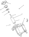
- An electric motor pump for example for a clothes washing machine, according to the invention, is generally referenced by 5.
- Said electric motor pump 5 comprises a rotor wheel 14 housed inside a rotor wheel chamber, which is not shown, since it is of the conventional type.
- Said rotor wheel 14 is connected to a suction conduit, for drawing liquids from external ducts, and to a pressure conduit, for pushing said liquid towards further external conduits.
- the electric motor pump 5 runs through hot cycles alternating with cold cycles.
- Said rotor wheel 14 is rotated around an axis XX by an electric motor 4 inside the electric motor pump 5, by means of a shaft 8.
- the electric motor 4 is of the synchronous type, with permanent magnets, in the present case of the single-phase type (it may be for example of the two-phase type).
- This electric motor 4 comprises a stator 10 with a pair of polar expansions 10A, which are wound around by conventional coils, said polar expansions 10A being such as to generate a magnetic field in the air gap, as usual in electric motors.
- the electric motor 4 also comprises a rotor chamber 2, which is defined in a sealed case 9.
- the electric motor 4 comprises a rotor 3 of the type comprising permanent magnets 13, and which is housed inside said rotor chamber 2 and which is separated from the walls of said rotor chamber.
- Rotor 3 and shaft 8 are per se able to move freely, although in a limited way, along rotation axis XX, between a maximum efficiency position, in which permanent magnets 13 are positioned in their magnetic equilibrium position, and positions deviating from said maximum efficiency position.
- the attraction force exerted by said permanent magnets is such as to normally position the rotor 3 and shaft 8 in maximum efficiency positions.
- Shaft 8 connected to rotor 3, is rotatably inserted into the stator structure by means of interposed bushings/bearings 7, 11.
- a sealing ring 1 is disposed in order to close said rotor chamber 2; said sealing ring 1 is formed by a generally axially symmetrical body of plastic material, provided with a central bore along rotation axis XX, for being passed through by shaft 8.
- the sealing ring 1 comprises an eccentric through bore 6.
- sealing ring 1 is shape coupled to an external sealing ring holding disc 12.
- the sealing ring 1 comprises an end portion defining an end lip 20, which is of generally conical shape directed outwardly (the conical shape may also comprise a frusto-conical shape).
- the inside of end lip 20 is originally provided for a light sliding contact with the electric motor pump shaft, so as to provide a certain sealing, even if due to friction with said shaft, in the course of time, said end lip progressively wears out.
- a bushing/bearing 7 is shape coupled to said sealing ring 1, in order to define a labyrinth 22, for decelerating and/or reducing the liquid inflow inside the rotor chamber 2, and which is able to inhibit dirt from entering the inside of the rotor chamber 2.
- the sealing ring holding disc 12, which is coaxial with shaft 8, comprises an annular protrusion 23, which is coaxial with axis XX, which defines a wall 31 opposed to said bore 6.
- a valve 30, of the flap type is formed by the bore 6 of sealing ring 1 and by opposed wall 31 of sealing ring holding disc 12.
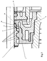
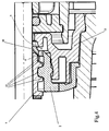
- the sealing ring 1 is able to deform between a first position ( fig. 1 and 3 ), in which said bore 6 is closed by said sealing ring holding disc 12, and a second position ( fig. 4 ), in which said bore 6 is separated from said sealing ring holding disc 12, so as to fluidly communicate said rotor chamber 2 with the outside.
- the rotor chamber 2 is subject to a variable pressure, varying between a pressure higher than the external ambient pressure, which is normally reached during hot cycles, by which water inside the rotor chamber 2 evaporates and vapor pushes outwardly, and a pressure lower than the external ambient pressure, which is normally reached by a quick temperature drop due to a cold cycle immediately following a hot cycle.
- valve 30 When the rotor chamber 2 is at a pressure higher than the ambient pressure, the valve 30 is closed, as shown in fig. 1 and 3 . In this situation, vapor exits the rotor chamber 2 passing through interstices formed by labyrinth 22, or between the bushing/bearing 7 and shaft 8, venting through the end lip 20, which therefore opens. It is to be noted that vapor pushes the bushing/bearing 7 against the sealing ring 1, and the sealing ring 1 against the sealing ring holding disc 12. Bore 6 of ring 1 is closed by the sealing ring holding disc 12.
- valve 30 When the rotor chamber is at a pressure lower than external ambient pressure, valve 30 opens. In fact, the external ambient pressure, since it is higher than the pressure inside the rotor chamber 2, pushes inwardly: the rotor 3 temporarily shifts inwardly, so that wall 31 of sealing ring holding disc 12 is temporarily separated from sealing ring 1, and bore 6 is opened.
- valve 30 is connected to labyrinth 22, it can fluidly communicate the rotor chamber 2 to the outside, so that air may pass into rotor chamber in order to achieve pressure equilibrium between the inside of rotor chamber 2 and the outside.
- a passage a is formed (shown in an exaggerated scale in fig. 4 , in order to be easily visible), which therefore permits a fluid passage b to be formed. Due to passage b, air passes through labyrinth 22 and reaches rotor chamber 2. Therefore, depression inside rotor chamber 2 ceases to exist and sealing ring 1 may return to said initial position ( fig. 1 and 3 ).
- valve 30 does not imply dirt entering said rotor chamber, since labyrinth 22 defined by contact ring and bushing/bearing is provided.
- Permanent magnets 13 may therefore remain in a magnetic equilibrium position, thus of maximum efficiency, without reducing overall hydraulic efficiency of electric motor pump.
- the greatest advantage of electric motor according to the present invention is its continuity regarding efficiency, since efficiency during hot cycles is same as during cold cycles, without efficiency drops due to movements of permanent magnets and friction between sealing ring lips and shaft.
- a further advantage of the present invention is its simple construction, which is a very important aspect for a mass produced item.
Landscapes
- Engineering & Computer Science (AREA)
- Power Engineering (AREA)
- Connection Of Motors, Electrical Generators, Mechanical Devices, And The Like (AREA)
- Motor Or Generator Frames (AREA)
Claims (10)
- Moteur électrique (4) comprenant un stator (10) du type ayant des extensions polaires de type shunt, une chambre du rotor (2) définie par une enveloppe scellée (9) fermée par une bague d'étanchéité (1), un rotor à aimant permanent (3) logé à l'intérieur de la dite chambre du rotor (2) et un axe (8) connecté au dit rotor (3), le dit moteur électrique (4) comportant une soupape (30) qui permet l'entrée de fluide dans la dite chambre du rotor, caractérisé en ce que la dite soupape (30) est formée par un trou traversant (6) prévu sur la dite bague d'étanchéité (1) et une paroi opposée (31) pour fermer le dit trou (6), la dite paroi (31) étant prévue dans une paroi d'un disque de maintien de la bague d'étanchéité (19) qui est formée couplée à la dite bague d'étanchéité (1).
- Moteur électrique selon la revendication 1, caractérisé en ce que la dite soupape (30) est du type unidirectionnel.
- Moteur électrique selon l'une quelconque des revendications 1 ou 2, caractérisé en ce que la dite soupape (30) est du type à clapet.
- Moteur électrique selon la revendication 1, caractérisé en ce que le dit trou (6) est parallèle à l'axe de rotation (XX) du dit rotor (3) et est dans une position excentrée.
- Moteur électrique selon l'une quelconque des revendications précédentes, caractérisé en ce que la dite bague d'étanchéité (1) comprend une partie terminale conique (20) avec des lèvres entourant le dit axe (8) et les dites lèvres ayant une forme conique dirigée vers l'extérieur.
- Moteur électrique selon la revendication 2, comportant un labyrinthe en communication de fluide avec la dite soupape unidirectionnelle.
- Moteur électrique selon la revendication 5 ou 6, caractérisé en ce que le dit axe (8) est supporté en rotation au moyen de coussinets/embases interposés (7, 11), le dit axe (8) s'étendant hors de la dite chambre du rotor (2) au-delà de la dite bague d'étanchéité (1), la dite bague d'étanchéité (1) étant capable de loger un des dits coussinets/embases (7).
- Moteur électrique selon la revendication 7, caractérisé en ce que le dit labyrinthe (22) est formé par des interstices prévus entre un coussinet/embase (7, 11) et la dite bague d'étanchéité (1).
- Moteur électrique selon la revendication 1, caractérisé en ce que la dite bague d'étanchéité (1) est capable de se déformer entre une première position, dans laquelle le dit trou (6) est fermé par le dit disque de maintien de la bague d'étanchéité (12), et une deuxième position, dans laquelle le dit trou (6) est séparé du dit disque de maintien de la bague d'étanchéité (12), de façon à faire communiquer de manière fluide la dite chambre du rotor (2) avec l'extérieur.
- Pompe (5) de moteur électrique, en particulier pour machine de lavage d'assiettes ou bien une machine de lavage de vêtements ou bien un appareil ménager similaire, la dite pompe (5) de moteur électrique comprenant une roue (14) de rotor et un moteur électrique (4) pour entraîner en rotation la dite roue de rotor, ledit moteur électrique (4) comprenant les réalisations selon l'une quelconque des revendications précédentes.
Priority Applications (3)
| Application Number | Priority Date | Filing Date | Title |
|---|---|---|---|
| EP08425089A EP2091133B1 (fr) | 2008-02-13 | 2008-02-13 | Moteur électrique et pompe électrique |
| ES08425089T ES2391594T3 (es) | 2008-02-13 | 2008-02-13 | Motor eléctrico y electrobomba |
| US12/368,811 US8128381B2 (en) | 2008-02-13 | 2009-02-10 | Electric motor and electropump |
Applications Claiming Priority (1)
| Application Number | Priority Date | Filing Date | Title |
|---|---|---|---|
| EP08425089A EP2091133B1 (fr) | 2008-02-13 | 2008-02-13 | Moteur électrique et pompe électrique |
Publications (2)
| Publication Number | Publication Date |
|---|---|
| EP2091133A1 EP2091133A1 (fr) | 2009-08-19 |
| EP2091133B1 true EP2091133B1 (fr) | 2012-08-15 |
Family
ID=39410364
Family Applications (1)
| Application Number | Title | Priority Date | Filing Date |
|---|---|---|---|
| EP08425089A Active EP2091133B1 (fr) | 2008-02-13 | 2008-02-13 | Moteur électrique et pompe électrique |
Country Status (3)
| Country | Link |
|---|---|
| US (1) | US8128381B2 (fr) |
| EP (1) | EP2091133B1 (fr) |
| ES (1) | ES2391594T3 (fr) |
Families Citing this family (11)
| Publication number | Priority date | Publication date | Assignee | Title |
|---|---|---|---|---|
| DE102010003432A1 (de) | 2010-03-30 | 2011-10-06 | BSH Bosch und Siemens Hausgeräte GmbH | Haushaltsgeschirrspülmaschine mit mindestens einer Pumpe, zugehörige Pumpe sowie Verfahren zu deren Herstellung |
| DE102012206189A1 (de) * | 2012-04-16 | 2013-10-17 | Robert Bosch Gmbh | Elektrische Maschine und Verfahren zum Betreiben einer elektrischen Maschine |
| DE102013211573A1 (de) * | 2013-06-19 | 2014-12-24 | BSH Bosch und Siemens Hausgeräte GmbH | Pumpe mit einer Verdrehsicherung und Haushaltsgerät mit einer solchen Pumpe |
| JP2015195668A (ja) * | 2014-03-31 | 2015-11-05 | ファナック株式会社 | シール部材を備えた電動機及び電動機の製造方法 |
| CN104373387B (zh) * | 2014-10-27 | 2015-08-19 | 扬州大学 | 一种水力性能优异的钟形进水流道及其应用方法 |
| CN105697389A (zh) * | 2014-12-11 | 2016-06-22 | 德昌电机(深圳)有限公司 | 泵及清洗装置 |
| CN106487155B (zh) * | 2015-08-31 | 2024-07-02 | 德昌电机(深圳)有限公司 | 液泵、电机及其轴套单元 |
| CN109163100B (zh) * | 2018-11-06 | 2024-06-11 | 深圳市创世纪机械有限公司 | 主轴的气密封结构 |
| DE102020113202B3 (de) * | 2020-05-15 | 2021-05-27 | Dr. Ing. H.C. F. Porsche Aktiengesellschaft | Spaltrohrmotor und Kraftfahrzeug mit einem Spaltrohrmotor |
| DE102022202277A1 (de) * | 2022-03-07 | 2023-09-07 | BSH Hausgeräte GmbH | Pumpe, Pumpensystem und wasserführendes Haushaltsgerät |
| CN115045842B (zh) * | 2022-06-30 | 2025-12-02 | 佛山市威灵洗涤电机制造有限公司 | 排水泵及空调器 |
Family Cites Families (9)
| Publication number | Priority date | Publication date | Assignee | Title |
|---|---|---|---|---|
| US2829286A (en) | 1955-06-16 | 1958-04-01 | Kaybee Engineering Company Inc | Sealed electric motor |
| GB1237633A (en) * | 1968-04-11 | 1971-06-30 | Marelli & C Spa Ercole | Improvements in or relating to electric water-pumps |
| JPS51111902A (en) * | 1975-03-26 | 1976-10-02 | Iwaki:Kk | Magnet pump |
| DE9116641U1 (de) * | 1991-06-22 | 1993-05-19 | Grundfos A/S, Bjerringbro | Gleitlager mit einem elastischen Mantel für einen Kreiselpumpenmotor |
| DE9210400U1 (de) * | 1992-08-04 | 1993-09-02 | Hanning Elektro-Werke GmbH & Co, 33813 Oerlinghausen | Von einem Elektromotor angetriebene Umwälz- oder Entleerungspumpe für wasserführende Haushaltsmaschinen |
| DE4300401C2 (de) * | 1993-01-09 | 2002-10-24 | Bosch Gmbh Robert | Elektrischer Lüftermotor |
| DE19702723A1 (de) * | 1997-01-27 | 1998-08-06 | Grundfos As | Naßlaufender Tauchmotor zum Antreiben einer Kreiselpumpe |
| WO2004073145A1 (fr) * | 2003-02-14 | 2004-08-26 | Mitsubishi Denki Kabushiki Kaisha | Pompe a carburant de type moteur cc |
| DE102004048557A1 (de) * | 2004-10-04 | 2006-04-06 | Aweco Appliance Systems Gmbh & Co. Kg | Flüssigkeitspumpe |
-
2008
- 2008-02-13 EP EP08425089A patent/EP2091133B1/fr active Active
- 2008-02-13 ES ES08425089T patent/ES2391594T3/es active Active
-
2009
- 2009-02-10 US US12/368,811 patent/US8128381B2/en active Active
Also Published As
| Publication number | Publication date |
|---|---|
| EP2091133A1 (fr) | 2009-08-19 |
| US8128381B2 (en) | 2012-03-06 |
| US20090202372A1 (en) | 2009-08-13 |
| ES2391594T3 (es) | 2012-11-28 |
Similar Documents
| Publication | Publication Date | Title |
|---|---|---|
| EP2091133B1 (fr) | Moteur électrique et pompe électrique | |
| US5215448A (en) | Combined boiler feed and condensate pump | |
| US10830240B2 (en) | Magnetic drive pump | |
| US10024324B2 (en) | Pump assembly | |
| JP4510638B2 (ja) | 玉軸受およびこの形式の軸受が装備された真空ポンプ | |
| JP2001123978A (ja) | 再生式インペラ・ディスクを有するシールなし一体型モータ・ポンプ | |
| US20110318175A1 (en) | Multi-stage centrifugal fan | |
| US10539143B2 (en) | Centrifugal pump having axially moveable impeller wheel for conveying different flow paths | |
| MXPA05004774A (es) | Bomba accionada electricamente. | |
| JP4059416B2 (ja) | 一体型モータポンプ | |
| JP5106077B2 (ja) | 潤滑剤シール式回転翼形油回転真空ポンプ | |
| CN104126074A (zh) | 湿运行离心泵 | |
| JP2000303986A5 (fr) | ||
| ITTO20090705A1 (it) | Capsulismo, particolarmente per turbomacchine, turbomacchina comprendente tale capsulismo e gruppo rotante per tale capsulismo | |
| EP3282128A1 (fr) | Moteur électrique amélioré pour un circulateur de fluide | |
| CN203114662U (zh) | 耐腐蚀分子泵 | |
| EP3759351A1 (fr) | Système de pompage à vide comportant une pompe à vide et son moteur | |
| US20160273542A1 (en) | Rotary pump with axially displaceable, closeable rotor | |
| CN100400892C (zh) | 电驱动的泵 | |
| US20200056616A1 (en) | Canned motor pump and method for manufacturing such a motor pump | |
| US6695576B2 (en) | Pump for liquids, in particular, a centrifugal pump for electric household appliances | |
| KR101705784B1 (ko) | 축하중 저감 구조를 갖는 터보블로어 | |
| CN103591054B (zh) | 离心泵轴封水冷散热保护系统 | |
| KR102583275B1 (ko) | 쉬라우드 임펠러 조립체 | |
| JP6479127B2 (ja) | 真空ポンプ |
Legal Events
| Date | Code | Title | Description |
|---|---|---|---|
| PUAI | Public reference made under article 153(3) epc to a published international application that has entered the european phase |
Free format text: ORIGINAL CODE: 0009012 |
|
| AK | Designated contracting states |
Kind code of ref document: A1 Designated state(s): AT BE BG CH CY CZ DE DK EE ES FI FR GB GR HR HU IE IS IT LI LT LU LV MC MT NL NO PL PT RO SE SI SK TR |
|
| AX | Request for extension of the european patent |
Extension state: AL BA MK RS |
|
| 17P | Request for examination filed |
Effective date: 20100219 |
|
| 17Q | First examination report despatched |
Effective date: 20100316 |
|
| AKX | Designation fees paid |
Designated state(s): AT BE BG CH CY CZ DE DK EE ES FI FR GB GR HR HU IE IS IT LI LT LU LV MC MT NL NO PL PT RO SE SI SK TR |
|
| REG | Reference to a national code |
Ref country code: DE Ref legal event code: R079 Ref document number: 602008017990 Country of ref document: DE Free format text: PREVIOUS MAIN CLASS: H02K0005100000 Ipc: H02K0005128000 |
|
| GRAP | Despatch of communication of intention to grant a patent |
Free format text: ORIGINAL CODE: EPIDOSNIGR1 |
|
| RIC1 | Information provided on ipc code assigned before grant |
Ipc: H02K 5/128 20060101AFI20120201BHEP Ipc: H02K 5/10 20060101ALI20120201BHEP |
|
| GRAS | Grant fee paid |
Free format text: ORIGINAL CODE: EPIDOSNIGR3 |
|
| GRAA | (expected) grant |
Free format text: ORIGINAL CODE: 0009210 |
|
| AK | Designated contracting states |
Kind code of ref document: B1 Designated state(s): AT BE BG CH CY CZ DE DK EE ES FI FR GB GR HR HU IE IS IT LI LT LU LV MC MT NL NO PL PT RO SE SI SK TR |
|
| REG | Reference to a national code |
Ref country code: GB Ref legal event code: FG4D Ref country code: CH Ref legal event code: EP Ref country code: AT Ref legal event code: REF Ref document number: 571251 Country of ref document: AT Kind code of ref document: T Effective date: 20120815 |
|
| GRAL | Information related to payment of fee for publishing/printing deleted |
Free format text: ORIGINAL CODE: EPIDOSDIGR3 |
|
| GRAS | Grant fee paid |
Free format text: ORIGINAL CODE: EPIDOSNIGR3 |
|
| REG | Reference to a national code |
Ref country code: IE Ref legal event code: FG4D |
|
| REG | Reference to a national code |
Ref country code: DE Ref legal event code: R096 Ref document number: 602008017990 Country of ref document: DE Effective date: 20121011 |
|
| REG | Reference to a national code |
Ref country code: ES Ref legal event code: FG2A Ref document number: 2391594 Country of ref document: ES Kind code of ref document: T3 Effective date: 20121128 |
|
| REG | Reference to a national code |
Ref country code: NL Ref legal event code: VDEP Effective date: 20120815 |
|
| REG | Reference to a national code |
Ref country code: AT Ref legal event code: MK05 Ref document number: 571251 Country of ref document: AT Kind code of ref document: T Effective date: 20120815 |
|
| PG25 | Lapsed in a contracting state [announced via postgrant information from national office to epo] |
Ref country code: HR Free format text: LAPSE BECAUSE OF FAILURE TO SUBMIT A TRANSLATION OF THE DESCRIPTION OR TO PAY THE FEE WITHIN THE PRESCRIBED TIME-LIMIT Effective date: 20120815 Ref country code: AT Free format text: LAPSE BECAUSE OF FAILURE TO SUBMIT A TRANSLATION OF THE DESCRIPTION OR TO PAY THE FEE WITHIN THE PRESCRIBED TIME-LIMIT Effective date: 20120815 Ref country code: LT Free format text: LAPSE BECAUSE OF FAILURE TO SUBMIT A TRANSLATION OF THE DESCRIPTION OR TO PAY THE FEE WITHIN THE PRESCRIBED TIME-LIMIT Effective date: 20120815 Ref country code: FI Free format text: LAPSE BECAUSE OF FAILURE TO SUBMIT A TRANSLATION OF THE DESCRIPTION OR TO PAY THE FEE WITHIN THE PRESCRIBED TIME-LIMIT Effective date: 20120815 Ref country code: IS Free format text: LAPSE BECAUSE OF FAILURE TO SUBMIT A TRANSLATION OF THE DESCRIPTION OR TO PAY THE FEE WITHIN THE PRESCRIBED TIME-LIMIT Effective date: 20121215 Ref country code: NO Free format text: LAPSE BECAUSE OF FAILURE TO SUBMIT A TRANSLATION OF THE DESCRIPTION OR TO PAY THE FEE WITHIN THE PRESCRIBED TIME-LIMIT Effective date: 20121115 Ref country code: CY Free format text: LAPSE BECAUSE OF FAILURE TO SUBMIT A TRANSLATION OF THE DESCRIPTION OR TO PAY THE FEE WITHIN THE PRESCRIBED TIME-LIMIT Effective date: 20120815 |
|
| PG25 | Lapsed in a contracting state [announced via postgrant information from national office to epo] |
Ref country code: SI Free format text: LAPSE BECAUSE OF FAILURE TO SUBMIT A TRANSLATION OF THE DESCRIPTION OR TO PAY THE FEE WITHIN THE PRESCRIBED TIME-LIMIT Effective date: 20120815 Ref country code: GR Free format text: LAPSE BECAUSE OF FAILURE TO SUBMIT A TRANSLATION OF THE DESCRIPTION OR TO PAY THE FEE WITHIN THE PRESCRIBED TIME-LIMIT Effective date: 20121116 Ref country code: PL Free format text: LAPSE BECAUSE OF FAILURE TO SUBMIT A TRANSLATION OF THE DESCRIPTION OR TO PAY THE FEE WITHIN THE PRESCRIBED TIME-LIMIT Effective date: 20120815 Ref country code: SE Free format text: LAPSE BECAUSE OF FAILURE TO SUBMIT A TRANSLATION OF THE DESCRIPTION OR TO PAY THE FEE WITHIN THE PRESCRIBED TIME-LIMIT Effective date: 20120815 Ref country code: BE Free format text: LAPSE BECAUSE OF FAILURE TO SUBMIT A TRANSLATION OF THE DESCRIPTION OR TO PAY THE FEE WITHIN THE PRESCRIBED TIME-LIMIT Effective date: 20120815 Ref country code: LV Free format text: LAPSE BECAUSE OF FAILURE TO SUBMIT A TRANSLATION OF THE DESCRIPTION OR TO PAY THE FEE WITHIN THE PRESCRIBED TIME-LIMIT Effective date: 20120815 Ref country code: PT Free format text: LAPSE BECAUSE OF FAILURE TO SUBMIT A TRANSLATION OF THE DESCRIPTION OR TO PAY THE FEE WITHIN THE PRESCRIBED TIME-LIMIT Effective date: 20121217 |
|
| REG | Reference to a national code |
Ref country code: SK Ref legal event code: T3 Ref document number: E 13075 Country of ref document: SK |
|
| PG25 | Lapsed in a contracting state [announced via postgrant information from national office to epo] |
Ref country code: NL Free format text: LAPSE BECAUSE OF FAILURE TO SUBMIT A TRANSLATION OF THE DESCRIPTION OR TO PAY THE FEE WITHIN THE PRESCRIBED TIME-LIMIT Effective date: 20120815 |
|
| PG25 | Lapsed in a contracting state [announced via postgrant information from national office to epo] |
Ref country code: RO Free format text: LAPSE BECAUSE OF FAILURE TO SUBMIT A TRANSLATION OF THE DESCRIPTION OR TO PAY THE FEE WITHIN THE PRESCRIBED TIME-LIMIT Effective date: 20120815 Ref country code: CZ Free format text: LAPSE BECAUSE OF FAILURE TO SUBMIT A TRANSLATION OF THE DESCRIPTION OR TO PAY THE FEE WITHIN THE PRESCRIBED TIME-LIMIT Effective date: 20120815 Ref country code: DK Free format text: LAPSE BECAUSE OF FAILURE TO SUBMIT A TRANSLATION OF THE DESCRIPTION OR TO PAY THE FEE WITHIN THE PRESCRIBED TIME-LIMIT Effective date: 20120815 Ref country code: EE Free format text: LAPSE BECAUSE OF FAILURE TO SUBMIT A TRANSLATION OF THE DESCRIPTION OR TO PAY THE FEE WITHIN THE PRESCRIBED TIME-LIMIT Effective date: 20120815 |
|
| PLBE | No opposition filed within time limit |
Free format text: ORIGINAL CODE: 0009261 |
|
| STAA | Information on the status of an ep patent application or granted ep patent |
Free format text: STATUS: NO OPPOSITION FILED WITHIN TIME LIMIT |
|
| 26N | No opposition filed |
Effective date: 20130516 |
|
| PG25 | Lapsed in a contracting state [announced via postgrant information from national office to epo] |
Ref country code: BG Free format text: LAPSE BECAUSE OF FAILURE TO SUBMIT A TRANSLATION OF THE DESCRIPTION OR TO PAY THE FEE WITHIN THE PRESCRIBED TIME-LIMIT Effective date: 20121115 |
|
| REG | Reference to a national code |
Ref country code: DE Ref legal event code: R097 Ref document number: 602008017990 Country of ref document: DE Effective date: 20130516 |
|
| PG25 | Lapsed in a contracting state [announced via postgrant information from national office to epo] |
Ref country code: MC Free format text: LAPSE BECAUSE OF NON-PAYMENT OF DUE FEES Effective date: 20130228 |
|
| REG | Reference to a national code |
Ref country code: CH Ref legal event code: PL |
|
| GBPC | Gb: european patent ceased through non-payment of renewal fee |
Effective date: 20130213 |
|
| PG25 | Lapsed in a contracting state [announced via postgrant information from national office to epo] |
Ref country code: CH Free format text: LAPSE BECAUSE OF NON-PAYMENT OF DUE FEES Effective date: 20130228 Ref country code: LI Free format text: LAPSE BECAUSE OF NON-PAYMENT OF DUE FEES Effective date: 20130228 |
|
| REG | Reference to a national code |
Ref country code: IE Ref legal event code: MM4A |
|
| PG25 | Lapsed in a contracting state [announced via postgrant information from national office to epo] |
Ref country code: IE Free format text: LAPSE BECAUSE OF NON-PAYMENT OF DUE FEES Effective date: 20130213 Ref country code: GB Free format text: LAPSE BECAUSE OF NON-PAYMENT OF DUE FEES Effective date: 20130213 |
|
| PG25 | Lapsed in a contracting state [announced via postgrant information from national office to epo] |
Ref country code: MT Free format text: LAPSE BECAUSE OF FAILURE TO SUBMIT A TRANSLATION OF THE DESCRIPTION OR TO PAY THE FEE WITHIN THE PRESCRIBED TIME-LIMIT Effective date: 20120815 |
|
| PG25 | Lapsed in a contracting state [announced via postgrant information from national office to epo] |
Ref country code: LU Free format text: LAPSE BECAUSE OF NON-PAYMENT OF DUE FEES Effective date: 20130213 Ref country code: HU Free format text: LAPSE BECAUSE OF FAILURE TO SUBMIT A TRANSLATION OF THE DESCRIPTION OR TO PAY THE FEE WITHIN THE PRESCRIBED TIME-LIMIT; INVALID AB INITIO Effective date: 20080213 |
|
| REG | Reference to a national code |
Ref country code: FR Ref legal event code: PLFP Year of fee payment: 9 |
|
| REG | Reference to a national code |
Ref country code: FR Ref legal event code: PLFP Year of fee payment: 10 |
|
| REG | Reference to a national code |
Ref country code: FR Ref legal event code: PLFP Year of fee payment: 11 |
|
| P01 | Opt-out of the competence of the unified patent court (upc) registered |
Effective date: 20230520 |
|
| PGFP | Annual fee paid to national office [announced via postgrant information from national office to epo] |
Ref country code: DE Payment date: 20250122 Year of fee payment: 18 |
|
| PGFP | Annual fee paid to national office [announced via postgrant information from national office to epo] |
Ref country code: ES Payment date: 20250303 Year of fee payment: 18 |
|
| PGFP | Annual fee paid to national office [announced via postgrant information from national office to epo] |
Ref country code: FR Payment date: 20250122 Year of fee payment: 18 |
|
| PGFP | Annual fee paid to national office [announced via postgrant information from national office to epo] |
Ref country code: IT Payment date: 20250121 Year of fee payment: 18 Ref country code: SK Payment date: 20250127 Year of fee payment: 18 |
|
| PGFP | Annual fee paid to national office [announced via postgrant information from national office to epo] |
Ref country code: TR Payment date: 20250128 Year of fee payment: 18 |