EP2091140A2 - Commutation électrique multiphasique destinée à couper un courant conduit par un regulateur de courant triphasé - Google Patents
Commutation électrique multiphasique destinée à couper un courant conduit par un regulateur de courant triphasé Download PDFInfo
- Publication number
- EP2091140A2 EP2091140A2 EP09001358A EP09001358A EP2091140A2 EP 2091140 A2 EP2091140 A2 EP 2091140A2 EP 09001358 A EP09001358 A EP 09001358A EP 09001358 A EP09001358 A EP 09001358A EP 2091140 A2 EP2091140 A2 EP 2091140A2
- Authority
- EP
- European Patent Office
- Prior art keywords
- capacitor
- thyristor
- phase
- current
- controller
- Prior art date
- Legal status (The legal status is an assumption and is not a legal conclusion. Google has not performed a legal analysis and makes no representation as to the accuracy of the status listed.)
- Withdrawn
Links
- 230000005611 electricity Effects 0.000 title abstract 2
- 238000000034 method Methods 0.000 claims abstract description 13
- 230000007935 neutral effect Effects 0.000 claims abstract description 12
- 239000003990 capacitor Substances 0.000 claims description 68
- 230000008878 coupling Effects 0.000 claims description 5
- 238000010168 coupling process Methods 0.000 claims description 5
- 238000005859 coupling reaction Methods 0.000 claims description 5
- 239000004020 conductor Substances 0.000 claims description 3
- 238000010791 quenching Methods 0.000 description 8
- 230000000171 quenching effect Effects 0.000 description 8
- 230000008569 process Effects 0.000 description 4
- 238000010248 power generation Methods 0.000 description 3
- 238000012217 deletion Methods 0.000 description 2
- 230000037430 deletion Effects 0.000 description 2
- 238000010586 diagram Methods 0.000 description 2
- 238000000926 separation method Methods 0.000 description 2
- 230000006978 adaptation Effects 0.000 description 1
- 230000002457 bidirectional effect Effects 0.000 description 1
- 238000013016 damping Methods 0.000 description 1
- 238000001514 detection method Methods 0.000 description 1
- 230000004907 flux Effects 0.000 description 1
- 238000009472 formulation Methods 0.000 description 1
- 238000005259 measurement Methods 0.000 description 1
- 239000000203 mixture Substances 0.000 description 1
- 230000010355 oscillation Effects 0.000 description 1
- 230000001172 regenerating effect Effects 0.000 description 1
- 230000001105 regulatory effect Effects 0.000 description 1
- 239000004065 semiconductor Substances 0.000 description 1
- 230000001360 synchronised effect Effects 0.000 description 1
- 230000001960 triggered effect Effects 0.000 description 1
- XLYOFNOQVPJJNP-UHFFFAOYSA-N water Substances O XLYOFNOQVPJJNP-UHFFFAOYSA-N 0.000 description 1
Images


Classifications
-
- H—ELECTRICITY
- H02—GENERATION; CONVERSION OR DISTRIBUTION OF ELECTRIC POWER
- H02M—APPARATUS FOR CONVERSION BETWEEN AC AND AC, BETWEEN AC AND DC, OR BETWEEN DC AND DC, AND FOR USE WITH MAINS OR SIMILAR POWER SUPPLY SYSTEMS; CONVERSION OF DC OR AC INPUT POWER INTO SURGE OUTPUT POWER; CONTROL OR REGULATION THEREOF
- H02M5/00—Conversion of AC power input into AC power output, e.g. for change of voltage, for change of frequency, for change of number of phases
- H02M5/02—Conversion of AC power input into AC power output, e.g. for change of voltage, for change of frequency, for change of number of phases without intermediate conversion into DC
- H02M5/04—Conversion of AC power input into AC power output, e.g. for change of voltage, for change of frequency, for change of number of phases without intermediate conversion into DC by static converters
- H02M5/22—Conversion of AC power input into AC power output, e.g. for change of voltage, for change of frequency, for change of number of phases without intermediate conversion into DC by static converters using discharge tubes with control electrode or semiconductor devices with control electrode
- H02M5/25—Conversion of AC power input into AC power output, e.g. for change of voltage, for change of frequency, for change of number of phases without intermediate conversion into DC by static converters using discharge tubes with control electrode or semiconductor devices with control electrode using devices of a thyratron or thyristor type requiring extinguishing means
- H02M5/257—Conversion of AC power input into AC power output, e.g. for change of voltage, for change of frequency, for change of number of phases without intermediate conversion into DC by static converters using discharge tubes with control electrode or semiconductor devices with control electrode using devices of a thyratron or thyristor type requiring extinguishing means using semiconductor devices only
-
- H—ELECTRICITY
- H02—GENERATION; CONVERSION OR DISTRIBUTION OF ELECTRIC POWER
- H02H—EMERGENCY PROTECTIVE CIRCUIT ARRANGEMENTS
- H02H7/00—Emergency protective circuit arrangements specially adapted for specific types of electric machines or apparatus or for sectionalised protection of cable or line systems, and effecting automatic switching in the event of an undesired change from normal working conditions
- H02H7/22—Emergency protective circuit arrangements specially adapted for specific types of electric machines or apparatus or for sectionalised protection of cable or line systems, and effecting automatic switching in the event of an undesired change from normal working conditions for distribution gear, e.g. bus-bar systems; for switching devices
- H02H7/222—Emergency protective circuit arrangements specially adapted for specific types of electric machines or apparatus or for sectionalised protection of cable or line systems, and effecting automatic switching in the event of an undesired change from normal working conditions for distribution gear, e.g. bus-bar systems; for switching devices for switches
Definitions
- the invention relates to a multi-phase electrical circuit for switching off a guided via a respective three-phase current, the neutral points of the voltage systems connected to the phases are not connected to each other via a neutral, and wherein the three-phase controller of each phase has two thyristors.
- the invention also relates to a method for switching off a current conducted via a thyristor of a three-phase controller.
- the currents over the To carry thyristors of three-phase controllers can increase to a multiple of their rated current.
- the thyristors are often oversized.
- the object of the invention is to provide a circuit and a method of the type mentioned, with which a fast shutdown of the thyristors with little effort is possible.
- the invention achieves this object by the circuit according to one of claims 1 or 5 and by the method according to one of claims 10 or 11.
- the star points of the voltage systems connected to the phases are not connected to one another via a neutral conductor and the three-phase controller of each phase has two thyristors.
- a single series circuit consisting of a capacitor and a number of phases corresponding number of parallel-connected erasure switches is connected in parallel.
- one of the quenching switches is turned on and from the capacitor, a current is driven through the quenching switch, which counteracts the guided over the associated thyristor current.
- the current conducted through the thyristor thus becomes zero so that the thyristor is turned off.
- the capacitor In the initial state of the procedure explained above, the capacitor must be charged to a negative voltage be.
- the invention provides that the capacitor can be charged via a diode bridge and a transformer.
- the capacitor is coupled via the diode bridge and the transformer with two phases of one of the two networks. By this arrangement, the capacitor can be charged to the desired negative voltage of the initial state.
- circuit according to the invention is used for coupling an electrical energy supply network and a generator, in particular of a wind power generation plant.
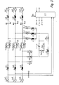
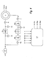
- FIGS. 1 to 3 each show a schematic circuit diagram of an embodiment of an electrical circuit according to the invention and FIG. 4 shows a schematic circuit diagram of an embodiment an inventive electrical circuit with a double-fed asynchronous generator with grid-connected stator.
- FIG. 1 is a three-phase circuit shown, in which the phases of two electrical networks are coupled to each other via a three-phase controller.
- the star points of the connected to the phases, input and output voltage systems are not connected to each other via a common neutral.
- the two networks are represented by the mains voltages Un1, Un2, Un3 and Uq1, Uq2, Uq3, wherein both networks are assigned a network inductance Ln1, Ln2, Ln3 and Lq1, Lq2, Lq3 in each of their phases.
- One of the two networks can also be a passive motor or generator load.
- the three-phase controller is represented in each case by the two thyristors T11, T12, T13 and T21, T22, T23 connected in parallel and in opposite directions. These thyristors are considered below as switches, which can be turned on in the forward direction by an ignition pulse and then are energized, and lock after an inversion of the current direction of the guided current and thus turn off the power.
- the mains voltage Un1, the associated network inductance Ln1, the two parallel-connected thyristors T11, T21, the network inductance Lq1 associated with the second network and the mains voltage Uq1 form a series circuit.
- the phases of the two networks are each connected in a star point, but the two star points are not connected. So there is no neutral.
- All thyristors are associated with a quenching device, which consists of a series circuit of a capacitor C and a parallel circuit, each having a coil L1, L2, L3 and one erase switch TL1, TL2, TL3.
- This quenching device is connected in parallel via diodes D1, D2, D3 to the thyristors T11, T21 or T12, T22 or T13, T23.
- the quenching device comprises a series circuit of a Umschwingthyristors TU and a Umschwingspule LU, which is connected in parallel to the capacitor C.
- the extinguishing switches TL1, TL2, TL3 may be thyristors.
- a controller ST is provided which generates output signals ZTn, ZTLn, ZTU for driving the thyristors, the clear switch and the turn-around thyristor.
- a current sensor W1, W2, W3 a flowing between the two networks load current is measured and passed a corresponding signal to the controller ST.
- the controller ST is coupled via bidirectional lines with other control or regulating systems.
- FIG. 1 By way of example only one of the three phases of the circuit will be described below FIG. 1 considered, namely the phase with the thyristors T11, T21. The same applies mutatis mutandis to the other two phases. Furthermore, it is assumed that the thyristor T21 conducts the considered phase and thus conducts a load current. Furthermore, it is assumed that the capacitor C is negatively charged, that is applied to the capacitor C, a voltage corresponding to that in the FIG. 1 indicated voltage arrow is directed against.
- the thyristor T21 As soon as the measured overload current reaches the threshold value, no further ignition pulses are output by the controller ST to the thyristors T11, T21. At the same time, the clear switch TL1 is turned on by the controller ST. Thus, the capacitor C forms a resonant circuit together with the coil L1. Via the capacitor C, the coil L1, the quenching switch TL1 and the thyristor T21, a larger oscillating current flows. This oscillating current counteracts the overload current conducted by the thyristor T21. When this oscillating current driven by the capacitor C reaches the value of the overload current, the thyristor T21 becomes de-energized. The overload current conducted by the thyristor T21 is completely compensated and thus zero. At this time, the entire overload current is no longer passed through the thyristor T21, but via the capacitor C. The thyristor T21 is thus turned off.
- the capacitor C is continuously charged positively by the oscillating current flowing through the quenching switch TL1.
- the consequence is that the voltage at the two grid inductances Ln1, Lq1 becomes smaller and smaller at some point the polarity changes.
- the two mains voltages Un1 and Uq1 remain substantially constant throughout the process. This is synonymous with the fact that the overload current flowing via the clear switch TL1 also becomes smaller and smaller. Eventually, this overload current will be zero, so that the clear switch TL1 is turned off.
- a series circuit of a diode Dov and a resistor Rov may be connected in parallel to the capacitor C.
- This series circuit acts as a voltage limit for the capacitor C.
- a varistor can also be connected in parallel with the capacitor C.
- the turning off of the thyristor T11 takes place in the manner explained with the aid of the extinguishing device. It should be noted at this point that the thyristors T11, T12, T13 are also replaced by diodes can. Furthermore, it is pointed out that - due to the missing neutral conductor - the sum of all phase currents must be equal to zero. Thus, the currents in two phases always flow in one direction and the current in the third phase in the opposite direction. A shutdown of all phases can thus be achieved in that, for example, the thyristors of the two phases are switched off with rectified current flow, even if the thyristor of the phase is turned on with the counter-current.
- the value of the negative voltage is selected so that the peak value of the illustrated oscillation current is greater than the maximum possible overload current.
- a switch S For initial charging of the capacitor C is in the circuit of FIG. 1 a switch S, an AC transformer Tr, a diode bridge DB and a ballast resistor Rv and a ballast Lv provided.
- the primary coil of the transformer Tr is connected via the switch S to two of the three phases of the first network Un1, Un2, Un3.
- the secondary coil of the transformer Tr is connected to the middle connection points of the diode bridge DB, while the outer connection points of the diode bridge DB are connected in parallel to the capacitor C. Between these outer connection points of the diode bridge DB and the capacitor C, the ballast resistor Rv and optionally the ballast Lv can be switched.
- the transformer Tr is the potential separation.
- the switch S can be switched on and off by the controller ST become.
- the diode bridge DB With the help of the diode bridge DB, the secondary voltage of the transformer Tr is rectified and the required for the negative charging of the capacitor C polarity of the transformer Tr ultimately provided voltage is generated.
- the charge current occurring during charging of the capacitor C can be limited by the series resistor Rv and possibly also by the ballast Lv.
- the ballast resistor Rv further causes a decoupling of the charging device described in an erase operation with respect to the changing voltage across the capacitor C.
- the switch S For initial charging of the capacitor C, the switch S is closed by the controller ST. As a result, a charging current is generated by the transformer Tr, which flows through a series circuit consisting of the secondary coil thereof, the diode bridge DB, the ballast resistor Rv, the capacitor C and the ballast Lv. By this charging current, the capacitor C is negatively charged. If the capacitor C has reached the desired negative for the initial state negative voltage, this negative voltage across the closed switch S and the transformer Tr is maintained permanently. In this state, only a trickle current flows through the aforementioned series circuit, which is smaller than the charging current.
- FIG. 2 is a circuit that is largely related to the circuit of FIG. 1 matches. It will therefore only those components and functions of the circuit below the FIG. 2 which is different from the circuit of the FIG. 1 differ. With regard to matching components and functions of the circuit of FIG. 2 will be on the description of the circuit of FIG. 1 directed.
- a three-phase transformer Tr, a switch S, a diode bridge DB and a ballast resistor Rv and a ballast Lv provided.
- the primary coils of the transformer Tr are connected to the phases of the first network Un1, Un2, Un3.
- the secondary coils of the transformer Tr are connected to the middle connection points of the diode bridge DB, while the outer connection points of the diode bridge DB are connected in parallel to the capacitor C via the switch S.
- the ballast resistor Rv and optionally the ballast Lv can be switched.
- the transformer Tr is the potential separation.
- the switch S can be switched on and off by the controller ST. With the help of the diode bridge DB is rectified and it is generated for the negative charging of the capacitor C polarity of the voltage provided by the transformer Tr available.
- the charge current occurring during charging of the capacitor C can be limited by the series resistor Rv and possibly also by the ballast Lv.
- the ballast resistor Rv further causes a decoupling of the charging device described in an erase operation with respect to the changing voltage across the capacitor C.
- the switch S For initial charging of the capacitor C, the switch S is closed by the controller ST. As a result, a charging current is generated by the transformer Tr, which flows through a series circuit consisting of the secondary coils thereof, the diode bridge DB, the ballast resistor Rv, the capacitor C and the ballast Lv. By this charging current, the capacitor C is negatively charged. If the capacitor C has reached the desired negative for the initial state negative voltage, this negative voltage across the closed switch S and the transformer Tr is maintained permanently. In this state, only a trickle current flows through the aforementioned series circuit, which is smaller than the charging current.
- FIG. 3 is a circuit that is largely related to the circuit of FIG. 1 matches. It will therefore only those components and functions of the circuit below the FIG. 3 which is different from the circuit of the FIG. 1 differ. With regard to matching components and functions of the circuit of FIG. 3 will be on the description of the circuit of FIG. 1 directed.
- the mains voltage Un1 is detected by means of the sensor V1 as a positive voltage. If, under these conditions, only the thyristor T11 and the quenching switch TL1 connected in the same direction are switched simultaneously by the control ST, then a current flows from the mains voltage Un1 via the parallel connection of the mains voltages Un2, Un3, the associated grid inductances Ln2, Ln3 and the downstream diodes D2, D3 to the capacitor C and from there via the clear switch TL1, the thyristor T11 and the grid inductance Ln1 back to the mains voltage Un1. From this current, the capacitor C is charged.
- the capacitor C can be charged by means of a single charging operation, as explained above. However, it is likewise possible for a plurality of such charging processes to be used over a plurality of network periods in order to charge the capacitor C. In the second option, the charge current flowing during charging can be selected smaller than in the first option.
- the described charging of the capacitor C results in a positive voltage on the capacitor C.
- the turn-around thyristor TU is turned on by the controller ST so as to reverse the polarity of the voltage on the capacitor C.
- FIG. 4 an electrical circuit of a double-fed asynchronous generator is shown with grid-connected stator. This circuit is used in particular in power generation plants, for example in wind power or hydropower or gas turbine power generation plants.
- a three-phase power supply network is connected to a transformer T, to which a stator switch Es is further connected, which in turn is connected to the stator of an asynchronous generator G.
- the Stator Switch It can be replaced by one of the electrical circuits of the FIGS. 1 to 3 be realized.
- the stator switch It therefore has at least one of the thyristors T11, T12, T12, T22, T13, T23 of the FIGS. 1 to 3 on.
- a voltage sensor is provided on the line side of the stator switch Es.
- a further voltage sensor is provided on the stator side of the stator switch Es.
- a current sensor is present on this stator side, which measures the stator current Is flowing via the stator switch Es.
- the network converter Npr and the motor inverter Mpr can have any desired structure, in particular they can be circuits which have a plurality of semiconductor components, for example diodes or transistors or the like.
- the intermediate circuit Cd is provided for storing a DC voltage and in particular has one or more capacitors.
- a current sensor is provided on the grid side of the grid inverter Npr.
- a further current sensor is present on the machine side of the motor inverter Mpr.
- a voltage sensor is provided, with which the intermediate circuit voltage Ud can be measured.
- the measurement signals of the mains voltage Un, the stator voltage Us, the intermediate circuit voltage Ud, the current Inp flowing through the line converter Npr, the stator current Is and the rotor current Ir are fed to a controller ST as input signals.
- This control ST generates a plurality of output signals ZES, ZNpr, ZMpr, with which the stator switch Es, the power converter Npr and the motor inverter Mpr can be controlled.
- stator switch Es In normal operation of this circuit, the stator switch Es is turned on. If the rotor is caused to rotate by an external force, for example by wind or water, a voltage is induced in the stator, which voltage is fed into the power supply network via the stator switch Es.
- the adaptation, in particular the synchronization of the voltage induced in the stator the mains voltage Un of the power supply network is achieved by the controller ST by a corresponding control of the power converter Npr and the motor inverter Mpr.
- the fault is caused by one of the electrical circuits of the FIGS. 1 to 3 realized stator switch Switched on by the ST control as quickly as possible.
- the Statorschalter It is able to perform a switchover from its conducting to the locked state, even under load and especially in the case of a fault in the power supply network.
- the switchover to the locked state is triggered by the control ST when a predetermined intermediate circuit voltage Du is reached or when a predetermined stator current Is or when another predetermined threshold value is reached.
- the grid-side inverter Npr is controlled by the controller ST such that it feeds a reactive current into the power grid. Furthermore, the two inverters Mpr, Npr are controlled by the controller ST in such a way that a desired active current is generated, which is required to maintain the intermediate circuit voltage Ud.
- the rotor-side converter Mpr is driven by the controller ST in such a way that the magnetic flux is synchronized to the faulty power supply network.
- the controller monitors the mains voltage Un and the stator voltage Us. If the difference between these two voltages becomes zero, which is equivalent to the voltage applied to the stator switch Es becoming zero, then the stator switch Es is again turned on by the control ST. Thereafter, the stator current Is controlled by the controller ST by means of the rotor-side inverter Mpr such that predetermined by the operator of the power grid requirements for the supply of energy in case of failure are met.
Landscapes
- Engineering & Computer Science (AREA)
- Power Engineering (AREA)
- Control Of Eletrric Generators (AREA)
- Control Of Electrical Variables (AREA)
Applications Claiming Priority (1)
| Application Number | Priority Date | Filing Date | Title |
|---|---|---|---|
| DE102008009278A DE102008009278A1 (de) | 2008-02-15 | 2008-02-15 | Mehrphasige elektrische Schaltung zum Abschalten eines über jeweils einen Drehstromsteller geführten Stroms |
Publications (2)
| Publication Number | Publication Date |
|---|---|
| EP2091140A2 true EP2091140A2 (fr) | 2009-08-19 |
| EP2091140A3 EP2091140A3 (fr) | 2012-08-15 |
Family
ID=40651642
Family Applications (1)
| Application Number | Title | Priority Date | Filing Date |
|---|---|---|---|
| EP09001358A Withdrawn EP2091140A3 (fr) | 2008-02-15 | 2009-01-31 | Commutation électrique multiphasique destinée à couper un courant conduit par un regulateur de courant triphasé |
Country Status (2)
| Country | Link |
|---|---|
| EP (1) | EP2091140A3 (fr) |
| DE (1) | DE102008009278A1 (fr) |
Family Cites Families (5)
| Publication number | Priority date | Publication date | Assignee | Title |
|---|---|---|---|---|
| DE1588689C3 (de) * | 1967-02-25 | 1980-12-18 | Siemens Ag, 1000 Berlin Und 8000 Muenchen | Stellglied mit einem von einem Zwei- oder Dreipunktregler gesteuerten Asynchronmotor |
| DE3118284C2 (de) * | 1981-05-08 | 1985-10-17 | Licentia Patent-Verwaltungs-Gmbh, 6000 Frankfurt | Anordnung zum Schutz von Brücken mit steuerbaren Halbleitern gegen Über- und Kurzschlußströme |
| DE19801708C1 (de) * | 1998-01-17 | 1999-08-12 | E U S Gmbh | Kurzschlußstrombegrenzer für die Begrenzung von Fehlerströmen in einem elektrischen Energienetz |
| DE10327344A1 (de) * | 2003-06-16 | 2005-01-27 | Repower Systems Ag | Windenergieanlage |
| US7253537B2 (en) * | 2005-12-08 | 2007-08-07 | General Electric Company | System and method of operating double fed induction generators |
-
2008
- 2008-02-15 DE DE102008009278A patent/DE102008009278A1/de not_active Ceased
-
2009
- 2009-01-31 EP EP09001358A patent/EP2091140A3/fr not_active Withdrawn
Non-Patent Citations (1)
| Title |
|---|
| None * |
Also Published As
| Publication number | Publication date |
|---|---|
| EP2091140A3 (fr) | 2012-08-15 |
| DE102008009278A1 (de) | 2009-08-27 |
Similar Documents
| Publication | Publication Date | Title |
|---|---|---|
| EP3172823B1 (fr) | Convertisseur continu/continu comportant un transformateur | |
| EP2187510B1 (fr) | Circuit de démarrage d'un convertisseur de courant | |
| EP2148417B1 (fr) | Dispositif onduleur pour un générateur photovoltaique avec plusieurs ondulateurs couplé en serie à leur entrée | |
| EP3039764B1 (fr) | Installation permettant le transfert d'une puissance électrique | |
| DE102017127311A1 (de) | Vorrichtung und Verfahren zur Vormagnetisierung eines Netztransformators in einem Stromrichtersystem | |
| DE10114075A1 (de) | Stromrichterschaltungsanordnung für Generatoren mit dynamisch veränderlicher Leistungsabgabe | |
| EP3602768B1 (fr) | Parc éolien comprenant plusieurs aérogénérateurs | |
| DE1943646C3 (de) | Regelanordnung zur Vermeidung der bei einem Lastabwurf einer Hochspannungs-Gleichstrom-Übertragungsanlage auftretenden netzfrequenten Spannungsüberhöhung | |
| DE102012206409A1 (de) | Verfahren zum Betreiben einer elektrischen Schaltung | |
| DE102011000459B4 (de) | Verfahren zur Lieferung von Blindstrom mit einem Umrichter sowie Umrichteranordnung und Energieversorgungsanlage | |
| EP3783783B1 (fr) | Agencement de régulation d'un flux de puissance dans un réseau à tension alternative et procédé de protection de l'agencement | |
| EP3913786B1 (fr) | Dispositif de conversion avec un convertisseur commuté par la ligne ainsi que procédé de démarrage du convertisseur | |
| EP3297115A1 (fr) | Système comprenant un dispositif d'accumulation d'énergie et un convertisseur d'énergie destiné à recevoir de l'énergie électrique provenant d'un réseau électrique et fournir l'énergie électrique au réseau électrique | |
| EP2856625B1 (fr) | Alimentation en tension pour un onduleur | |
| EP3021475B1 (fr) | Circuit bidirectionnel de convertisseur ayant une séparation de potentiel et procédé de fonctionnement d'un circuit bidirectionnel de convertisseur | |
| EP1870996B1 (fr) | Circuit pour alimenter d'énergie electrique dans un reseau de distribution électrique | |
| DE102008009276A1 (de) | Elektrische Schaltung insbesondere für einen doppelt gespeisten Asynchrongenerator mit netzgekoppeltem Stator | |
| EP2117108A2 (fr) | Procédé de démarrage d'un système destiné à la production d'énergie électrique | |
| EP2091140A2 (fr) | Commutation électrique multiphasique destinée à couper un courant conduit par un regulateur de courant triphasé | |
| EP3331118B1 (fr) | Installation de transfert d'énergie électrique | |
| EP3741023B1 (fr) | Dispositif et procédé pour commander un flux de charge dans un réseau à tension alternative | |
| EP3751718A1 (fr) | Procédé de traitement de défauts dans une ligne de tension continue ainsi que dispositif convertisseur de courant permettant la mise en oeuvre dudit procédé | |
| DE102020112723A1 (de) | Wechselrichter mit drei Brückenzweigen und Verfahren zum Betreiben eines derartigen Wechselrichters | |
| DE102008064079A1 (de) | Verfahren und elektrische Schaltung zur Erzeugung elektrischer Energie | |
| DE102008009279A1 (de) | Ein- oder mehrphasige elektrische Schaltung zum Abschalten eines über einen Wechselstrom- oder Drehstromsteller geführten Stroms |
Legal Events
| Date | Code | Title | Description |
|---|---|---|---|
| PUAI | Public reference made under article 153(3) epc to a published international application that has entered the european phase |
Free format text: ORIGINAL CODE: 0009012 |
|
| AK | Designated contracting states |
Kind code of ref document: A2 Designated state(s): AT BE BG CH CY CZ DE DK EE ES FI FR GB GR HR HU IE IS IT LI LT LU LV MC MK MT NL NO PL PT RO SE SI SK TR |
|
| AX | Request for extension of the european patent |
Extension state: AL BA RS |
|
| PUAL | Search report despatched |
Free format text: ORIGINAL CODE: 0009013 |
|
| AK | Designated contracting states |
Kind code of ref document: A3 Designated state(s): AT BE BG CH CY CZ DE DK EE ES FI FR GB GR HR HU IE IS IT LI LT LU LV MC MK MT NL NO PL PT RO SE SI SK TR |
|
| AX | Request for extension of the european patent |
Extension state: AL BA RS |
|
| RIC1 | Information provided on ipc code assigned before grant |
Ipc: H02M 5/257 20060101AFI20120709BHEP |
|
| 17P | Request for examination filed |
Effective date: 20130207 |
|
| AKX | Designation fees paid |
Designated state(s): AT BE BG CH CY CZ DE DK EE ES FI FR GB GR HR HU IE IS IT LI LT LU LV MC MK MT NL NO PL PT RO SE SI SK TR |
|
| RAP1 | Party data changed (applicant data changed or rights of an application transferred) |
Owner name: GE ENERGY POWER CONVERSION TECHNOLOGY LIMITED |
|
| 17Q | First examination report despatched |
Effective date: 20180416 |
|
| RIC1 | Information provided on ipc code assigned before grant |
Ipc: H02H 7/06 20060101ALI20190716BHEP Ipc: H02M 5/257 20060101AFI20190716BHEP |
|
| GRAP | Despatch of communication of intention to grant a patent |
Free format text: ORIGINAL CODE: EPIDOSNIGR1 |
|
| INTG | Intention to grant announced |
Effective date: 20190913 |
|
| RIN1 | Information on inventor provided before grant (corrected) |
Inventor name: EGGERT, BERNHARD |
|
| STAA | Information on the status of an ep patent application or granted ep patent |
Free format text: STATUS: THE APPLICATION IS DEEMED TO BE WITHDRAWN |
|
| 18D | Application deemed to be withdrawn |
Effective date: 20200124 |