EP2091148A1 - Geräuschdämpfungsfilter vom Typ BAW, der digital neu konfiguriert werden kann und Verfahren - Google Patents
Geräuschdämpfungsfilter vom Typ BAW, der digital neu konfiguriert werden kann und Verfahren Download PDFInfo
- Publication number
- EP2091148A1 EP2091148A1 EP09368005A EP09368005A EP2091148A1 EP 2091148 A1 EP2091148 A1 EP 2091148A1 EP 09368005 A EP09368005 A EP 09368005A EP 09368005 A EP09368005 A EP 09368005A EP 2091148 A1 EP2091148 A1 EP 2091148A1
- Authority
- EP
- European Patent Office
- Prior art keywords
- resonator
- parallel
- series
- branch
- baw
- Prior art date
- Legal status (The legal status is an assumption and is not a legal conclusion. Google has not performed a legal analysis and makes no representation as to the accuracy of the status listed.)
- Withdrawn
Links
- 238000000034 method Methods 0.000 title claims abstract description 12
- 239000003990 capacitor Substances 0.000 claims abstract description 22
- 230000004044 response Effects 0.000 claims description 9
- 230000000694 effects Effects 0.000 claims description 5
- 238000004891 communication Methods 0.000 claims description 3
- 238000004519 manufacturing process Methods 0.000 claims description 3
- 230000008569 process Effects 0.000 claims description 3
- 238000001514 detection method Methods 0.000 claims description 2
- 238000001914 filtration Methods 0.000 description 11
- 239000000758 substrate Substances 0.000 description 6
- 239000000463 material Substances 0.000 description 5
- 238000009413 insulation Methods 0.000 description 4
- PXHVJJICTQNCMI-UHFFFAOYSA-N Nickel Chemical compound [Ni] PXHVJJICTQNCMI-UHFFFAOYSA-N 0.000 description 3
- 239000000919 ceramic Substances 0.000 description 3
- 238000010586 diagram Methods 0.000 description 3
- 239000004065 semiconductor Substances 0.000 description 3
- ZOKXTWBITQBERF-UHFFFAOYSA-N Molybdenum Chemical compound [Mo] ZOKXTWBITQBERF-UHFFFAOYSA-N 0.000 description 2
- XUIMIQQOPSSXEZ-UHFFFAOYSA-N Silicon Chemical compound [Si] XUIMIQQOPSSXEZ-UHFFFAOYSA-N 0.000 description 2
- 229910052782 aluminium Inorganic materials 0.000 description 2
- XAGFODPZIPBFFR-UHFFFAOYSA-N aluminium Chemical compound [Al] XAGFODPZIPBFFR-UHFFFAOYSA-N 0.000 description 2
- 230000008901 benefit Effects 0.000 description 2
- 230000008859 change Effects 0.000 description 2
- 238000005229 chemical vapour deposition Methods 0.000 description 2
- 239000010949 copper Substances 0.000 description 2
- 239000010931 gold Substances 0.000 description 2
- 238000003780 insertion Methods 0.000 description 2
- 230000037431 insertion Effects 0.000 description 2
- 230000010354 integration Effects 0.000 description 2
- 229910052750 molybdenum Inorganic materials 0.000 description 2
- 239000011733 molybdenum Substances 0.000 description 2
- 238000012545 processing Methods 0.000 description 2
- 238000011160 research Methods 0.000 description 2
- 229910052710 silicon Inorganic materials 0.000 description 2
- 239000010703 silicon Substances 0.000 description 2
- 239000010936 titanium Substances 0.000 description 2
- JBRZTFJDHDCESZ-UHFFFAOYSA-N AsGa Chemical compound [As]#[Ga] JBRZTFJDHDCESZ-UHFFFAOYSA-N 0.000 description 1
- RYGMFSIKBFXOCR-UHFFFAOYSA-N Copper Chemical compound [Cu] RYGMFSIKBFXOCR-UHFFFAOYSA-N 0.000 description 1
- BQCADISMDOOEFD-UHFFFAOYSA-N Silver Chemical compound [Ag] BQCADISMDOOEFD-UHFFFAOYSA-N 0.000 description 1
- RTAQQCXQSZGOHL-UHFFFAOYSA-N Titanium Chemical compound [Ti] RTAQQCXQSZGOHL-UHFFFAOYSA-N 0.000 description 1
- 230000005540 biological transmission Effects 0.000 description 1
- 230000002301 combined effect Effects 0.000 description 1
- 229910052802 copper Inorganic materials 0.000 description 1
- 230000008878 coupling Effects 0.000 description 1
- 238000010168 coupling process Methods 0.000 description 1
- 238000005859 coupling reaction Methods 0.000 description 1
- 238000000151 deposition Methods 0.000 description 1
- 238000013461 design Methods 0.000 description 1
- 238000006073 displacement reaction Methods 0.000 description 1
- 230000009977 dual effect Effects 0.000 description 1
- 238000001704 evaporation Methods 0.000 description 1
- 230000008020 evaporation Effects 0.000 description 1
- 238000000605 extraction Methods 0.000 description 1
- 239000010408 film Substances 0.000 description 1
- 239000011521 glass Substances 0.000 description 1
- PCHJSUWPFVWCPO-UHFFFAOYSA-N gold Chemical compound [Au] PCHJSUWPFVWCPO-UHFFFAOYSA-N 0.000 description 1
- 229910052737 gold Inorganic materials 0.000 description 1
- 239000012528 membrane Substances 0.000 description 1
- 229910052751 metal Inorganic materials 0.000 description 1
- 239000002184 metal Substances 0.000 description 1
- 239000003607 modifier Substances 0.000 description 1
- 229910052759 nickel Inorganic materials 0.000 description 1
- 230000010349 pulsation Effects 0.000 description 1
- 230000009467 reduction Effects 0.000 description 1
- 229910052709 silver Inorganic materials 0.000 description 1
- 239000004332 silver Substances 0.000 description 1
- 238000005507 spraying Methods 0.000 description 1
- 238000004544 sputter deposition Methods 0.000 description 1
- 230000003068 static effect Effects 0.000 description 1
- 229910052715 tantalum Inorganic materials 0.000 description 1
- GUVRBAGPIYLISA-UHFFFAOYSA-N tantalum atom Chemical compound [Ta] GUVRBAGPIYLISA-UHFFFAOYSA-N 0.000 description 1
- 239000010409 thin film Substances 0.000 description 1
- 229910052719 titanium Inorganic materials 0.000 description 1
- WFKWXMTUELFFGS-UHFFFAOYSA-N tungsten Chemical compound [W] WFKWXMTUELFFGS-UHFFFAOYSA-N 0.000 description 1
- 229910052721 tungsten Inorganic materials 0.000 description 1
- 239000010937 tungsten Substances 0.000 description 1
- 238000001771 vacuum deposition Methods 0.000 description 1
Images


Classifications
-
- H—ELECTRICITY
- H03—ELECTRONIC CIRCUITRY
- H03H—IMPEDANCE NETWORKS, e.g. RESONANT CIRCUITS; RESONATORS
- H03H9/00—Networks comprising electromechanical or electro-acoustic elements; Electromechanical resonators
- H03H9/46—Filters
- H03H9/54—Filters comprising resonators of piezoelectric or electrostrictive material
- H03H9/58—Multiple crystal filters
- H03H9/60—Electric coupling means therefor
- H03H9/605—Electric coupling means therefor consisting of a ladder configuration
-
- H—ELECTRICITY
- H03—ELECTRONIC CIRCUITRY
- H03H—IMPEDANCE NETWORKS, e.g. RESONANT CIRCUITS; RESONATORS
- H03H9/00—Networks comprising electromechanical or electro-acoustic elements; Electromechanical resonators
- H03H9/46—Filters
- H03H9/54—Filters comprising resonators of piezoelectric or electrostrictive material
- H03H9/542—Filters comprising resonators of piezoelectric or electrostrictive material including passive elements
Definitions
- the present invention relates to electronic circuits and in particular a filter circuit comprising BAW acoustic resonators reconfigurable numerically.
- SAW Surface Acoustic Resonator
- BAW Bulk Acoustic Resonator
- the acoustic resonator is located on the surface of a semiconductor product while in the second, it is disposed within a volume delimited between a lower electrode and an upper electrode so that the wave acoustic develops in this same volume.
- BAW type resonators are the subject of intense research by manufacturers of semiconductor products because these components make it possible to envisage a very thorough integration of the filtering circuits and, consequently, suggest a significant decrease in the cost of manufacture. of these same circuits.
- BAW resonators allow to consider higher frequencies than those implemented by SAW, while offering a particularly small footprint.
- This configuration is performed up to now by means of varactor that is connected in series or in parallel on the resonators and that comes commanding by applying an analog voltage.
- the present invention aims to provide a filter structure - suitable for mobile telephony - consisting of acoustic resonators BAW type which is easily configurable.
- Another object of the present invention is to provide a filter comprising acoustic resonators that are inexpensive to produce and which immediately allow a completely digital control of the frequency adjustment.
- a third object of the present invention is to provide a filter circuit comprising BAW resonators perfectly integrable on a semiconductor substrate and easily configurable digitally.
- a BAW-type acoustic resonator filtering circuit comprising at least a first and a second quadrupole connected in cascade, said quadrupoles each comprising a series branch provided with a first acoustic resonator of BAW type. and a parallel branch also equipped with a BAW type acoustic resonator.
- the first BAW resonator has a series resonance frequency substantially also at the parallel resonance frequency of said second acoustic resonator.
- the circuit is characterized in that the parallel branch of the first quadrupole comprises a first capacitor connected in series with said second resonator and, in parallel with said capacitor, a first switching transistor controlled by a first control potential and making it possible to bypass said capacity.
- the second quadrupole comprises a second capacitor connected in series with said second resonator and, in parallel therewith, a second switching transistor controlled by a second control potential and intended to short-circuit said capacitor.
- control potentials of the first, second (and more if applicable) switching transistors make it possible to constitute a completely digital control bus for controlling the filtering characteristics of the circuit with the acoustic resonators.
- the resonators are all of the Surface Mounted Resonator (SMR) type arranged on a Bragg mirror.
- SMR Surface Mounted Resonator
- the filtering circuit serves for the realization of a 4 th generation mobile telephony reception circuit.
- the invention also provides a method of reducing interference to a receiving circuit for a mobile telephone having a filter circuit based on a cascade of cells each having a parallel branch having a first BAW, and a serial branch. provided with a second BAW, said second BAW being connected in series with a capacitor having a switching transistor connected to its terminals.
- a reconfigurable filtering circuit which is particularly suitable for producing a reception circuit of an RF signal that can be used in particular in mobile telephony, and integrable on Very Large Scale Integration (VLSI) type circuit.
- VLSI Very Large Scale Integration
- WCDMA Wide Code Division Multiplexing Access
- WCDMA Wide Code Division Multiplexing Access
- the filtering circuit comprises a set of acoustic resonators type Bulk Acoustic Wave (BAW) which is carried out by means of known techniques for depositing thin layers (thin film) by means of spraying techniques (sputtering), evaporation vacuum or CVD ( Chemical Vapor Deposition ) well known.
- BAW Bulk Acoustic Wave
- the figure 1 illustrates more particularly the structure of a BAW resonator Film Bulk Acoustic Resonator (FBAR) which consists of a layer of piezoelectric material 13 having acoustic characteristics, electrodes 12 enclosing this layer and acoustic insulation of the assembly relative to a substrate silicon substrate 100 made of silicon (Si), gallium arsenide (GaAs), glass or ceramic.
- the piezoelectric material may be ZnO, ALN, ZnS or any ferroelectric ceramic known to those skilled in the art.
- the electrodes can be made of any metal suitable for the desired application, such as, for example, tungsten (W), aluminum (AL), copper (Cu), molybdenum (MO), nickel (Ni). ), titanium (Ti), silver (Ag), gold (Au) or tantalum (Ta).
- acoustic insulation is achieved by means of a membrane 11 disposed above a cavity 14 providing insulation with respect to the substrate 10.
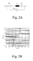
- the figure 2 illustrates more particularly a dual structure of a resonator known in the literature as Surface Mounted Resonator (SMR). Indeed, we see the resonator composed of two electrodes 22 enclosing a layer 23 disposed above a reflective element such as a receiver or mirror Bragg 21 for example. This reflecting mirror is composed a stack of layers having different acoustic properties and dielectric constants arranged on a substrate 20. In this way, a minimum loss of acoustic waves within the substrate 20 is ensured.
- SMR Surface Mounted Resonator
- the circuit which will be described later will comprise exclusively resonators of the SMR type as represented in FIG. figure 2 , but it is clear that one skilled in the art can achieve the invention by substituting these resonators SMR FBAR type resonators and the invention is not limited by the particular acoustic insulation technique used for the realization of the BAW resonator.
- a BAW type resonator whether it be a FBAR or SMR type resonator, is well known and will not be described further.
- the resonance frequencies of the BAW resonances typically vary from 0.5 Ghz to 5 Ghz and these values of the nature of the material used and the layer thicknesses that are used.
- the BAW resonator has two resonance frequencies which are characteristic of the nature of the piezoelectric material used (ZnO, ALN, ZnS or any ferroelectric ceramic known to a person skilled in the art)
- the figure 2 illustrates the equivalent electric diagram of a BAW resonator, conventionally referred to as Butterworth-Van-Dyke (BVD), with Ra, La and Ca accounting for acoustic resonance frequency and acoustic losses.
- BAW Butterworth-Van-Dyke
- the figure 3 illustrates the characteristic curve of a resonator, highlighting two resonance pulses, respectively series ( ⁇ s corresponding to a minimum impedance) and parallel ( ⁇ p corresponding to a maximum impedance). Outside the neighborhood of the two resonance pulses, the resonator behaves capacitively
- the values of the pulsations ⁇ s and ⁇ p depend on the thickness of the piezoelectric material and the difference between these two values results from the electromechanical coupling coefficient.
- the filter consists of a set of cells, respectively 310-330, which are each in the form of a quadrupole.
- the cell 310 has two inputs, respectively 301 and 302, and two outputs (not numbered) which are connected to the two inputs of the quadrupole forming the next cell 320 etc.. figure 3 it can be seen that the quadrupole of the cell 330 has two outputs 303 and 304 which are the output electrodes of the filter.
- Each of the quadrupoles constituted by the cells 310-330 consists of a series branch (respectively 315, 325, 335) comprising a first BAW resonator (respectively 311, 321, 331), and a parallel branch (resp. 326, 336) having a second BAW resonator (respectively 312, 322, 332).
- the BAW resonators (respectively 312, 322, 332) of the parallel branch are sized to have a parallel resonance frequency (anti-resonance) substantially equal to the frequency of series resonance of the BAW resonator (resp 311, 321, 3312) in the series branch as illustrated in FIG. figure 5 .
- each of the parallel branches 316 and 326 comprise a capacitor (respectively 313, 323, 333) connected in series with the parallel BAW resonator (respectively 312, 322, 332).
- an MOS transistor (respectively 314, 324 and 334) has two source and drain electrodes which are connected in parallel with the capacitor (respectively 313, 323, 333) and a gate electrode receiving a capacitor. control potential for controlling the short circuit or not of the capacity.
- the figure 3 thus illustrates a set of three cells in cascade, perfectly identical, each having a capacity (respectively 313, 323 and 333) to vary substantially the characteristics of the individual cell.
- the figure 3 thus highlights a filtering circuit, provided with BAW resonators situated respectively in the series and parallel branches of each of the cells, as well as a set of control electrodes constituting a real digital bus allowing a digital control of the acoustic characteristics of the resonator.
- the circuit of the figure 3 thus offers a particularly elegant and inexpensive solution for making a digital control interface for a filter with BAW resonators, making it possible to perform sophisticated digital processing cheaply.
- the capacitors are passive components which have a quality factor whose value is in a range from 30 to 50.
- the capacitors are integrated into the "parallel" branch. Which is of little concern to the overall quality factor of the filter cell. This is a significant advantage of the filter circuit described, despite its apparent simplicity.
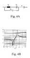
- Equation (III) highlights the insertion of a pole at zero frequency, but it is observed that the other values are not modified. Equation (II) also shows that the series association of a capacitance and a resonator causes the zeros to change in the frequency response. More particularly, by introducing a capacitance value, it is noted that the series resonance frequency is shifted to the left, while the static value of the capacitance of the resonator tends to decrease.
- the Figure 4B illustrates more particularly this effect due to the introduction of a capacitance in series with a resonator located in the parallel branch of a cell.
- the resonators of SERIE resonators or Xs which are located in a series branch of a cell
- PARALLEL resonators or Xp
- the series resonances ( ⁇ s) of the PARALLELE resonators determine the position of the zeros in such a way that a change in their impedance leads to a variation of these same zeros.
- the figure 6 illustrates the evolution of the frequency response of the filter when the three capacities 313, 323 and 333 are all implemented.
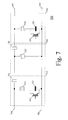
- the figure 7 illustrates a simplified version of the filter circuit 700 of the figure 3 having only three cells 710, 720 and 730.
- the cell 710 is identical to the cell 310 of the figure 3 .
- the cell 720 has no capacity in its parallel branch, while the cell 730 does not have a BAW resonator in its series branch, unlike the cell 330 of the figure 3 .
- the filter 700 differs from the filter of the figure 3 by deleting capacitance 323, transistor 324 and resonator 331.
- the filter circuit of the figure 7 is thus a fifth-order circuit, inexpensive to achieve, and can be finely tuned, completely digital, by means of the control voltages on the gates of transistors 314 and 334. It has been observed that this circuit, little expensive to perform, is suitable for the realization of a reception circuit complies with the WCDMA standard (2110-2170 MHz).
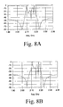
- the figure 8A indeed illustrates the frequency response of the filter when the transistors 314 and 334 are both put into the state of forced conduction, bypass 313 and 333 respectively.
- the filter (2103-2177 MHz) does not comply with the W-CDMA standard.
- the transistor 314 is then locked, which implements the capacitor 313, and thus reduces by 20% the bandwidth of the filter (2110 -2170 MHz), as illustrated in FIG. Figure 8B .
- the effect resulting from the insertion of the capacitance 313 on the displacement of the zeros is thus observed, illustrated in FIG. Figure 8C .
- the invention is advantageously applied in mobile telephony, when a reception circuit is located in an area in which another mobile phone transmits and is likely to come into interference and disrupt the operation of the receiver circuit.
Landscapes
- Physics & Mathematics (AREA)
- Acoustics & Sound (AREA)
- Chemical & Material Sciences (AREA)
- Crystallography & Structural Chemistry (AREA)
- Piezo-Electric Or Mechanical Vibrators, Or Delay Or Filter Circuits (AREA)
Applications Claiming Priority (1)
| Application Number | Priority Date | Filing Date | Title |
|---|---|---|---|
| FR0800827A FR2927742A1 (fr) | 2008-02-15 | 2008-02-15 | Filtre a resonateur acoustiques de type baw reconfigurable par voie numerique et procede |
Publications (1)
| Publication Number | Publication Date |
|---|---|
| EP2091148A1 true EP2091148A1 (de) | 2009-08-19 |
Family
ID=39730660
Family Applications (1)
| Application Number | Title | Priority Date | Filing Date |
|---|---|---|---|
| EP09368005A Withdrawn EP2091148A1 (de) | 2008-02-15 | 2009-02-13 | Geräuschdämpfungsfilter vom Typ BAW, der digital neu konfiguriert werden kann und Verfahren |
Country Status (4)
| Country | Link |
|---|---|
| US (1) | US8665038B2 (de) |
| EP (1) | EP2091148A1 (de) |
| CN (1) | CN101572532A (de) |
| FR (1) | FR2927742A1 (de) |
Families Citing this family (44)
| Publication number | Priority date | Publication date | Assignee | Title |
|---|---|---|---|---|
| KR101716335B1 (ko) | 2010-12-03 | 2017-03-15 | 삼성전자주식회사 | Bawr을 이용한 저역 통과 필터 |
| CN103929148B (zh) * | 2013-01-11 | 2017-09-19 | 中兴通讯股份有限公司 | 一种低插损压电声波带通滤波器及实现方法 |
| US9208274B2 (en) | 2013-03-15 | 2015-12-08 | Resonant Inc. | Network synthesis design of microwave acoustic wave filters |
| CN105247786B (zh) * | 2013-05-28 | 2018-01-12 | 株式会社村田制作所 | 可调谐滤波器 |
| JP6477725B2 (ja) * | 2014-12-10 | 2019-03-06 | 株式会社村田製作所 | 可変フィルタ回路 |
| JP6390787B2 (ja) * | 2015-03-30 | 2018-09-19 | 株式会社村田製作所 | 高周波フィルタ、フロントエンド回路、および通信機器 |
| CN105141262B (zh) * | 2015-07-21 | 2018-06-05 | 苏州能讯高能半导体有限公司 | 一种适用于f类或逆f类功率放大器的放大模块 |
| US10050603B2 (en) * | 2015-11-04 | 2018-08-14 | Mediatek Inc. | Frequency tunable filter with voltage stressed relaxed switch, and associated apparatus |
| US9608595B1 (en) * | 2015-11-13 | 2017-03-28 | Resonant Inc. | Acoustic wave filter with enhanced rejection |
| CN106253873B (zh) * | 2015-11-24 | 2019-08-09 | 苏州能讯高能半导体有限公司 | 一种薄膜体声波谐振器谐波调谐放大模块 |
| WO2017170071A1 (ja) * | 2016-03-31 | 2017-10-05 | 株式会社村田製作所 | 周波数可変フィルタ、rfフロントエンド回路、および、通信端末 |
| KR102115112B1 (ko) | 2016-05-27 | 2020-05-25 | 가부시키가이샤 무라타 세이사쿠쇼 | 고주파 필터 회로, 멀티플렉서, 고주파 프론트 엔드 회로 및 통신 장치 |
| CN109196778B (zh) * | 2016-05-27 | 2022-06-14 | 株式会社村田制作所 | 高频滤波电路、高频前端电路以及通信装置 |
| WO2018016279A1 (ja) | 2016-07-22 | 2018-01-25 | 株式会社村田製作所 | 高周波フィルタ回路、マルチプレクサ、高周波フロントエンド回路及び通信装置 |
| DE102016114662B4 (de) | 2016-08-08 | 2022-03-03 | Snaptrack, Inc. | Rekonfigurierbares mikroakustisches Filter und Duplexer mit rekonfigurierbarem mikroakustischem Filter |
| WO2018051864A1 (ja) * | 2016-09-16 | 2018-03-22 | 株式会社村田製作所 | 高周波フロントエンド回路及び通信装置 |
| WO2018052073A1 (ja) | 2016-09-16 | 2018-03-22 | 株式会社村田製作所 | 弾性波フィルタ装置、マルチプレクサ、高周波フロントエンド回路及び通信装置 |
| WO2018056224A1 (ja) | 2016-09-21 | 2018-03-29 | 株式会社村田製作所 | 弾性波装置、高周波フロントエンド回路および通信装置 |
| CN109792238B (zh) | 2016-09-26 | 2023-01-03 | 株式会社村田制作所 | 弹性波滤波器装置、高频前端电路以及通信装置 |
| WO2018061950A1 (ja) * | 2016-09-29 | 2018-04-05 | 株式会社村田製作所 | 弾性波フィルタ装置、マルチプレクサ、高周波フロントエンド回路及び通信装置 |
| WO2018061878A1 (ja) | 2016-09-29 | 2018-04-05 | 株式会社村田製作所 | 弾性波装置、高周波フロントエンド回路および通信装置 |
| WO2018061949A1 (ja) * | 2016-09-29 | 2018-04-05 | 株式会社村田製作所 | 弾性波フィルタ装置、マルチプレクサ、高周波フロントエンド回路及び通信装置 |
| WO2018061783A1 (ja) | 2016-09-30 | 2018-04-05 | 株式会社村田製作所 | 弾性波フィルタ装置、高周波フロントエンド回路及び通信装置 |
| US20180175817A1 (en) * | 2016-12-19 | 2018-06-21 | Futurewei Technologies, Inc. | Method to design ceramic filters with finite transmission zeros |
| WO2018135538A1 (ja) * | 2017-01-19 | 2018-07-26 | 株式会社村田製作所 | 高周波フィルタ、高周波フロントエンド回路、および通信装置 |
| WO2018139320A1 (ja) * | 2017-01-30 | 2018-08-02 | 株式会社村田製作所 | 高周波フィルタ、高周波フロントエンド回路及び通信装置 |
| US10256792B2 (en) | 2017-02-03 | 2019-04-09 | Samsung Electro-Mechanics Co., Ltd. | Filter module and front-end module including the same |
| US10511286B2 (en) * | 2017-02-03 | 2019-12-17 | Samsung Electro-Mechanics Co., Ltd. | Variable frequency filter |
| US10547287B2 (en) * | 2017-02-03 | 2020-01-28 | Samsung Electro-Mechanics Co., Ltd. | Filter and front end module including the same |
| US10547286B2 (en) | 2017-02-03 | 2020-01-28 | Samsung Electro-Mechanics Co., Ltd. | Filter and front end module including the same |
| WO2018147135A1 (ja) | 2017-02-07 | 2018-08-16 | 株式会社村田製作所 | 高周波フィルタ、高周波フロントエンド回路及び通信装置 |
| CN110383687B (zh) | 2017-03-01 | 2023-02-17 | 株式会社村田制作所 | 高频滤波器、多工器、高频前端电路以及通信装置 |
| WO2018186227A1 (ja) | 2017-04-03 | 2018-10-11 | 株式会社村田製作所 | 弾性波フィルタ装置、デュプレクサ、高周波フロントエンド回路、および通信装置 |
| WO2019003855A1 (ja) | 2017-06-28 | 2019-01-03 | 株式会社村田製作所 | 高周波フィルタ、マルチプレクサ、高周波フロントエンド回路および通信装置 |
| WO2019003619A1 (ja) | 2017-06-28 | 2019-01-03 | 株式会社村田製作所 | 高周波フィルタ、マルチプレクサ、高周波フロントエンド回路および通信装置 |
| WO2019013015A1 (ja) | 2017-07-10 | 2019-01-17 | 株式会社村田製作所 | 高周波フィルタ、マルチプレクサ、高周波フロントエンド回路および通信装置 |
| WO2019073899A1 (ja) * | 2017-10-10 | 2019-04-18 | 株式会社村田製作所 | マルチプレクサおよび高周波フィルタ |
| WO2019078157A1 (ja) * | 2017-10-16 | 2019-04-25 | 株式会社村田製作所 | 弾性波フィルタ、マルチプレクサ、高周波フロントエンド回路および通信装置 |
| US11652463B2 (en) | 2018-06-14 | 2023-05-16 | International Business Machines Corporation | Electrically tunable surface acoustic wave resonator |
| US10790801B2 (en) * | 2018-09-07 | 2020-09-29 | Vtt Technical Research Centre Of Finland Ltd | Loaded resonators for adjusting frequency response of acoustic wave resonators |
| US10979019B2 (en) | 2019-06-11 | 2021-04-13 | Globalfoundries Singapore Pte. Ltd. | Reconfigurable resonator devices, methods of forming reconfigurable resonator devices, and operations thereof |
| CN111130501A (zh) * | 2020-01-07 | 2020-05-08 | 诺思(天津)微系统有限责任公司 | 一种滤波器、双工器及多工器 |
| CN114785315B (zh) * | 2022-06-22 | 2022-12-16 | 华南理工大学 | 一种可开关式声波滤波器、模组及制作方法 |
| CN116230575B (zh) * | 2023-04-26 | 2023-09-29 | 长鑫存储技术有限公司 | 半导体测试结构及半导体参数测试方法 |
Citations (1)
| Publication number | Priority date | Publication date | Assignee | Title |
|---|---|---|---|---|
| US20050212612A1 (en) * | 2004-01-30 | 2005-09-29 | Kabushiki Kaisha Toshiba | Tunable filter and portable telephone |
Family Cites Families (12)
| Publication number | Priority date | Publication date | Assignee | Title |
|---|---|---|---|---|
| EP0732805B1 (de) * | 1995-03-15 | 2003-01-15 | Matsushita Electric Industrial Co., Ltd. | Akustischer Oberflächenwellenfilter |
| US5793261A (en) * | 1997-04-10 | 1998-08-11 | Rf Monolithics, Inc. | Saw stabilized FSK oscillator circuit |
| JP2000101380A (ja) * | 1998-09-25 | 2000-04-07 | Murata Mfg Co Ltd | 共振回路、フィルタ、送受共用器および通信装置 |
| EP1035648A3 (de) * | 1999-03-10 | 2000-12-27 | Matsushita Electric Industrial Co., Ltd. | Bereichsumschaltbares Filter mit einem Oberflächenwellenresonator und Antennenduplexer mit solch einem Filter |
| GB9916901D0 (en) * | 1999-07-19 | 1999-09-22 | Cambridge Silicon Radio Ltd | Adjustable filter |
| JP3704442B2 (ja) * | 1999-08-26 | 2005-10-12 | 株式会社日立製作所 | 無線端末 |
| JP3830843B2 (ja) * | 2002-03-28 | 2006-10-11 | 株式会社東芝 | 薄膜圧電共振子 |
| US7030718B1 (en) * | 2002-08-09 | 2006-04-18 | National Semiconductor Corporation | Apparatus and method for extending tuning range of electro-acoustic film resonators |
| KR100548130B1 (ko) * | 2004-02-21 | 2006-02-02 | 삼성전자주식회사 | 광대역 튜너블 대역통과필터 및 이를 이용한 다중밴드광대역 튜너블 대역통과필터 |
| US7719389B2 (en) * | 2007-08-09 | 2010-05-18 | Intel Corporation | System and method for controlling resonance frequency of film bulk acoustic resonator devices |
| FR2920612B1 (fr) * | 2007-09-03 | 2009-12-04 | St Microelectronics Sa | Circuit d'accord en frequence pour filtre treillis |
| US8073414B2 (en) * | 2008-06-27 | 2011-12-06 | Sirf Technology Inc. | Auto-tuning system for an on-chip RF filter |
-
2008
- 2008-02-15 FR FR0800827A patent/FR2927742A1/fr not_active Withdrawn
-
2009
- 2009-02-13 CN CNA2009100066760A patent/CN101572532A/zh active Pending
- 2009-02-13 EP EP09368005A patent/EP2091148A1/de not_active Withdrawn
- 2009-02-13 US US12/371,415 patent/US8665038B2/en active Active
Patent Citations (1)
| Publication number | Priority date | Publication date | Assignee | Title |
|---|---|---|---|---|
| US20050212612A1 (en) * | 2004-01-30 | 2005-09-29 | Kabushiki Kaisha Toshiba | Tunable filter and portable telephone |
Non-Patent Citations (3)
| Title |
|---|
| EL HASSAN M ET AL: "A New Method to Reconfigure BAW-SMR Filters Using CMOS Transistors", MICROWAVE SYMPOSIUM, 2007. IEEE/MTT-S INTERNATIONAL, IEEE, PI, 1 June 2007 (2007-06-01), pages 1603 - 1606, XP031112255, ISBN: 978-1-4244-0687-6 * |
| EL HASSAN M ET AL: "Reconfiguration of Bulk Acoustic Wave Filters: Application to WLAN 802.11b/g (2.40-2.48 GHz)", ELECTRONICS, CIRCUITS AND SYSTEMS, 2006. ICECS '06. 13TH IEEE INTERNAT IONAL CONFERENCE ON, IEEE, PI, 1 December 2006 (2006-12-01), pages 395 - 398, XP031111509, ISBN: 978-1-4244-0394-3 * |
| EL HASSAN M: "A New Method to Reconfigure B-W-SMR Filters Using CMOS Transistors", MICROWAVE SYMFOSIUM, 2007. IEEE/MTT-S INTERNATIONAL, IEEE, PI, 1 June 2007 (2007-06-01), pages 1603 - 1606 |
Also Published As
| Publication number | Publication date |
|---|---|
| US8665038B2 (en) | 2014-03-04 |
| CN101572532A (zh) | 2009-11-04 |
| US20090251235A1 (en) | 2009-10-08 |
| FR2927742A1 (fr) | 2009-08-21 |
Similar Documents
| Publication | Publication Date | Title |
|---|---|---|
| EP2091148A1 (de) | Geräuschdämpfungsfilter vom Typ BAW, der digital neu konfiguriert werden kann und Verfahren | |
| EP2713508B1 (de) | Akustische Struktur, die mit mindestens einem Resonator und mindestens einer in dieselbe piezo- oder ferroelektrische Schicht kointegrierten Kapazität ausgestattet ist | |
| EP3010149B1 (de) | Resonanzschaltung mit variabler frequenz und impedanz | |
| EP2628242B1 (de) | Oberflächenschallwellen-bandpassfilter mit integrierter akustischer führung mit impedanz- und/oder modusumwandlung | |
| FR2974691B1 (fr) | Dispositif electromecanique a ondes acoustiques comprenant une zone de transduction et une cavite etendue | |
| US10404233B2 (en) | Tunable resonator element, filter circuit and method | |
| EP2405574B1 (de) | Vorrichtung zur Adaptation der Impedanz einer Komponente, die einen adaptierbaren Impedanzfilter auf der Basis eines Materials vom Typ Perowskit umfasst | |
| FR2905208A1 (fr) | Filtre a resonateurs a ondes de lamb couples. | |
| EP2091147A1 (de) | Filterkreislauf mit gekoppelten akustischen Resonatoren | |
| FR2905207A1 (fr) | Filtre commutable a resonateurs. | |
| EP1885063A1 (de) | Filterkreislauf mit Geräuschdämpfern | |
| FR2939986A1 (fr) | Circuit de filtrage comportant des resonateurs baw couples et autorisant une adaptation d'impedance | |
| FR2883432A1 (fr) | Circuit de filtrage accordable en frequence integrable, comportant un jeu de resonateurs baw | |
| FR2888060A1 (fr) | Circuit de filtrage passe-bande dote de resonateurs acoustiques | |
| EP2901551A1 (de) | Akustische vorrichtung mit einem einstellbaren photonischen kristall aus piezoelektrischen elementen | |
| EP2509221B1 (de) | Schaltung mit Resonator Filters | |
| WO2005078752A1 (fr) | Dispositif de type microsysteme electromecanique a film mince piezoelectrique | |
| FR3136325A1 (fr) | Dispositif a ondes elastiques de surface | |
| FR3162108A1 (fr) | Dispositif à ondes élastiques | |
| FR3136327A1 (fr) | Dispositif a ondes elastiques de surface | |
| EP4427296A1 (de) | Rekonfigurierbare filtervorrichtung und system zur erfassung von hochfrequenzsignalen mit einer derartigen filtervorrichtung | |
| FR3157992A1 (fr) | Dispositif à ondes élastiques | |
| HK1136398A (en) | Bulk acoustic wave resonator filter being digitally reconfigurable, with process | |
| EP0398442A1 (de) | Halbleiteranordnung mit einem aktiven Filter im hohen und ultrahohen Frequenzgebiet |
Legal Events
| Date | Code | Title | Description |
|---|---|---|---|
| PUAI | Public reference made under article 153(3) epc to a published international application that has entered the european phase |
Free format text: ORIGINAL CODE: 0009012 |
|
| AK | Designated contracting states |
Kind code of ref document: A1 Designated state(s): AT BE BG CH CY CZ DE DK EE ES FI FR GB GR HR HU IE IS IT LI LT LU LV MC MK MT NL NO PL PT RO SE SI SK TR |
|
| AX | Request for extension of the european patent |
Extension state: AL BA RS |
|
| RIN1 | Information on inventor provided before grant (corrected) |
Inventor name: EL HASSAN, MOUSTAPHA Inventor name: KERHERVE, ERIC Inventor name: DEVAL, YANN Inventor name: SHIRAKAWA, ALEXANDRE AUGUSTO Inventor name: BELOT, DIDIER |
|
| 17P | Request for examination filed |
Effective date: 20100219 |
|
| 17Q | First examination report despatched |
Effective date: 20100318 |
|
| AKX | Designation fees paid |
Designated state(s): AT BE BG CH CY CZ DE DK EE ES FI FR GB GR HR HU IE IS IT LI LT LU LV MC MK MT NL NO PL PT RO SE SI SK TR |
|
| STAA | Information on the status of an ep patent application or granted ep patent |
Free format text: STATUS: THE APPLICATION IS DEEMED TO BE WITHDRAWN |
|
| 18D | Application deemed to be withdrawn |
Effective date: 20140902 |