EP2091228A1 - Fernsteuerungssystem - Google Patents
Fernsteuerungssystem Download PDFInfo
- Publication number
- EP2091228A1 EP2091228A1 EP07859743A EP07859743A EP2091228A1 EP 2091228 A1 EP2091228 A1 EP 2091228A1 EP 07859743 A EP07859743 A EP 07859743A EP 07859743 A EP07859743 A EP 07859743A EP 2091228 A1 EP2091228 A1 EP 2091228A1
- Authority
- EP
- European Patent Office
- Prior art keywords
- command
- video output
- output apparatus
- bus
- video
- Prior art date
- Legal status (The legal status is an assumption and is not a legal conclusion. Google has not performed a legal analysis and makes no representation as to the accuracy of the status listed.)
- Withdrawn
Links
Images












Classifications
-
- G—PHYSICS
- G08—SIGNALLING
- G08C—TRANSMISSION SYSTEMS FOR MEASURED VALUES, CONTROL OR SIMILAR SIGNALS
- G08C17/00—Arrangements for transmitting signals characterised by the use of a wireless electrical link
-
- G—PHYSICS
- G08—SIGNALLING
- G08C—TRANSMISSION SYSTEMS FOR MEASURED VALUES, CONTROL OR SIMILAR SIGNALS
- G08C23/00—Non-electrical signal transmission systems, e.g. optical systems
- G08C23/04—Non-electrical signal transmission systems, e.g. optical systems using light waves, e.g. infrared
-
- H—ELECTRICITY
- H04—ELECTRIC COMMUNICATION TECHNIQUE
- H04N—PICTORIAL COMMUNICATION, e.g. TELEVISION
- H04N21/00—Selective content distribution, e.g. interactive television or video on demand [VOD]
- H04N21/40—Client devices specifically adapted for the reception of or interaction with content, e.g. set-top-box [STB]; Operations thereof
- H04N21/41—Structure of client; Structure of client peripherals
- H04N21/4104—Peripherals receiving signals from specially adapted client devices
- H04N21/4135—Peripherals receiving signals from specially adapted client devices external recorder
-
- H—ELECTRICITY
- H04—ELECTRIC COMMUNICATION TECHNIQUE
- H04N—PICTORIAL COMMUNICATION, e.g. TELEVISION
- H04N21/00—Selective content distribution, e.g. interactive television or video on demand [VOD]
- H04N21/40—Client devices specifically adapted for the reception of or interaction with content, e.g. set-top-box [STB]; Operations thereof
- H04N21/41—Structure of client; Structure of client peripherals
- H04N21/422—Input-only peripherals, i.e. input devices connected to specially adapted client devices, e.g. global positioning system [GPS]
- H04N21/42204—User interfaces specially adapted for controlling a client device through a remote control device; Remote control devices therefor
-
- H—ELECTRICITY
- H04—ELECTRIC COMMUNICATION TECHNIQUE
- H04N—PICTORIAL COMMUNICATION, e.g. TELEVISION
- H04N21/00—Selective content distribution, e.g. interactive television or video on demand [VOD]
- H04N21/40—Client devices specifically adapted for the reception of or interaction with content, e.g. set-top-box [STB]; Operations thereof
- H04N21/41—Structure of client; Structure of client peripherals
- H04N21/422—Input-only peripherals, i.e. input devices connected to specially adapted client devices, e.g. global positioning system [GPS]
- H04N21/42204—User interfaces specially adapted for controlling a client device through a remote control device; Remote control devices therefor
- H04N21/42206—User interfaces specially adapted for controlling a client device through a remote control device; Remote control devices therefor characterized by hardware details
- H04N21/4221—Dedicated function buttons, e.g. for the control of an EPG, subtitles, aspect ratio, picture-in-picture or teletext
-
- H—ELECTRICITY
- H04—ELECTRIC COMMUNICATION TECHNIQUE
- H04N—PICTORIAL COMMUNICATION, e.g. TELEVISION
- H04N21/00—Selective content distribution, e.g. interactive television or video on demand [VOD]
- H04N21/40—Client devices specifically adapted for the reception of or interaction with content, e.g. set-top-box [STB]; Operations thereof
- H04N21/43—Processing of content or additional data, e.g. demultiplexing additional data from a digital video stream; Elementary client operations, e.g. monitoring of home network or synchronising decoder's clock; Client middleware
- H04N21/436—Interfacing a local distribution network, e.g. communicating with another STB or one or more peripheral devices inside the home
- H04N21/4363—Adapting the video stream to a specific local network, e.g. a Bluetooth® network
- H04N21/43632—Adapting the video stream to a specific local network, e.g. a Bluetooth® network involving a wired protocol, e.g. IEEE 1394
- H04N21/43635—HDMI
-
- G—PHYSICS
- G08—SIGNALLING
- G08C—TRANSMISSION SYSTEMS FOR MEASURED VALUES, CONTROL OR SIMILAR SIGNALS
- G08C2201/00—Transmission systems of control signals via wireless link
- G08C2201/40—Remote control systems using repeaters, converters, gateways
-
- G—PHYSICS
- G08—SIGNALLING
- G08C—TRANSMISSION SYSTEMS FOR MEASURED VALUES, CONTROL OR SIMILAR SIGNALS
- G08C2201/00—Transmission systems of control signals via wireless link
- G08C2201/90—Additional features
- G08C2201/92—Universal remote control
-
- H—ELECTRICITY
- H04—ELECTRIC COMMUNICATION TECHNIQUE
- H04N—PICTORIAL COMMUNICATION, e.g. TELEVISION
- H04N21/00—Selective content distribution, e.g. interactive television or video on demand [VOD]
- H04N21/40—Client devices specifically adapted for the reception of or interaction with content, e.g. set-top-box [STB]; Operations thereof
- H04N21/47—End-user applications
- H04N21/482—End-user interface for programme selection
-
- H—ELECTRICITY
- H04—ELECTRIC COMMUNICATION TECHNIQUE
- H04N—PICTORIAL COMMUNICATION, e.g. TELEVISION
- H04N21/00—Selective content distribution, e.g. interactive television or video on demand [VOD]
- H04N21/40—Client devices specifically adapted for the reception of or interaction with content, e.g. set-top-box [STB]; Operations thereof
- H04N21/47—End-user applications
- H04N21/485—End-user interface for client configuration
Definitions
- the present invention relates to remote control systems, and particularly to a remote control system which allows plural devices to be controlled by one remote controller.
- CEC Consumer Electronics Control
- HDMI High-Definition Multimedia Interface
- CEC Consumer Electronics Control
- HDMI High-Definition Multimedia Interface
- This is a function in which a television and various AV devices are connected by an HDMI cable, and transmit and receive CEC commands to each other via a CEC bus included in the HDMI cable.
- CEC defines a command which is transmitted with the destination of the command being specified, and a broadcast command for notifying a command to all CEC-compliant devices connected by HDMI, and communication is carried out using a combination of these commands.
- the CEC command includes the transmission destination device logical address, transmission destination device logical address, an operating code, and an operand.
- Non-Patent Reference 1 defines One Touch Play, Routing Control, Device Menu Control, Remote Control Pass Through, and so on, as applications using a CEC command.
- FIG. 2 device control in the conventional remote control system shall be described using FIG. 2 .
- a remote control system includes a television 101, an AV amplifier 102, a DVD player 103, an external speaker 104, a set top box 105, and a controller 106.
- the television 101 is a device for outputting video and audio outputted from a device connected via an HDMI cable.
- the AV amplifier 102 to which HDMI input terminal the DVD player 103 is connected, receives video and audio from the DVD player 103 via the HDMI input terminal, and outputs the video outputted from the DVD player 103 to the television 101 connected to an HDMI output terminal, while outputting audio from the external speaker 104. Furthermore, the AV amplifier 102 can switch between the input from another device not shown in the diagram and the input from the DVD player 103, and output video to the television 101.
- the DVD player 103 is a device which decodes video content recorded on a DVD, and outputs video and audio via the HDMI cable.
- the set top box 105 is a device which outputs video and audio of a cable television broadcast, via the HDMI cable.
- the DVD player 103 when the DVD player 103 starts playback, for example, the DVD player 103 transmits a ⁇ Text View On> command or an ⁇ Image View On> command to the television 101, and transmits an ⁇ Active Source> command indicating the start of video output.
- the television 101 and the AV amplifier 102 which receive the respective commands, each perform input switching automatically so that the video of the DVD player 103 is outputted based on the parameters of the commands. Furthermore, when the television 101 is OFF, the television automatically turns ON.
- the signal transmitted from the controller 106 is received by the television 101, and the television 101 transmits a command corresponding to the signal of the controller, to the DVD player 103.
- the DVD player 103 performs the corresponding operation thereby enabling the user to operate the DVD player 103 using the controller of the television 101.
- FIG. 3 Another example of device control in the conventional remote control system shall be described using FIG. 3 .
- a remote control system includes a television 301, a DVD player 302, a DVD recorder 303, a set top box 304, and a controller 305.
- the television 301 is a device for outputting video and audio outputted from a device connected via an HDMI cable.
- the DVD player 302 is a device which decodes video content recorded on a DVD, and outputs video and audio via the HDMI cable.
- the DVD recorder 303 is a device which decodes video content recorded on a DVD, and outputs video and audio via the HDMI cable. Furthermore, the DVD recorder 303 has a function for receiving and encoding video and audio, and recording the encoded video and audio on a recording DVD.
- the set top box 304 is a device which outputs video and audio of a cable television broadcast, via the HDMI cable.
- DDC communication is a function for inquiries: from a device (called a source device) connected by the HDMI cable, which transmits video and audio; to a device (called a sink device) which receives video and audio; regarding the device-type information of the sink device, the reproducible video and audio format, the physical address assigned to the source device, and so on.
- the logical address is an address given according to terminals connected by the HDMI cable, and is, for example, 1.0.0.0 when connected to a first terminal of the television, and 2.0.0.0 when connected to the second terminal.
- the DVD player 302 when the DVD player 302 starts playback, for example, the DVD player 302 transmits an ⁇ Active Source> command, which is a broadcast command indicating the start of video and audio output, with the physical address of the transmission source device as a parameter.
- the television 301 Upon receiving the command, the television 301 automatically performs input switching, based on the parameter of the ⁇ Active Source> command, so that the video of the DVD player 302 is outputted. Furthermore, when the television 301 is OFF, the television automatically turns ON.
- the signal transmitted from the controller 305 is received by the set top box 304.
- the set top box 304 transfers a CEC command corresponding to the signal received from the controller 305, to the DVD player 302.
- the DVD player 302 receiving the command performs an operation corresponding to the command.
- the user is able to operate the DVD player 302 by operating the controller 305 of the set top box 304.
- Patent Reference 1 in an AV system including an AV bus for transmitting data signals such as a command, a video signal, and an audio signal, between a television and respective devices in the AV system, the respective devices are controlled by operating the television.
- Patent Reference 1 the device control in Patent Reference 1 shall be described using FIG. 4 .
- Respective devices in an AV system are connected by an AV bus, and a signal passing through the bus has the form of a packet. Furthermore, each packet includes a transmission source address indicating the device that transmitted the data, and a destination address indicating the destination of the data.
- a television 311 receives a command transmitted from a controller 315, and transmits a command to the AV bus according to the details of the received command.
- each of a DVD player 312, a DVD recorder 313, and a set top box 314 analyzes and executes the command when the destination address of the command is addressed to it. Furthermore, when the command is not addressed to it, the command is disregarded without being analyzed.
- a signal indicating power ON is transmitted.
- the television 311 performs the checking of the connection state of devices connected to the AV bus, the detection of malfunctions, and so on.
- the television 311 displays a first control window on a screen. Icons indicating AV devices such as the DVD player, and a cursor are displayed on the first control window. The user can move the cursor by pressing UP, DOWN, LEFT, and RIGHT buttons on the controller 315, and activate, in the television 311, a program corresponding to the icon indicated by the cursor, by pressing an ENTER button.
- the television 311 displays a second control window. Icons for setting the operating mode of the DVD player, such as playback and stop, and a cursor are displayed on the second control window. By performing the same operation as in the case of the first control window, the user can activate a program corresponding to the icon indicated by the cursor. In the case of performing playback using the DVD player 312, the user points the cursor to the icon indicating playback and presses the ENTER button. Then, the television 311 generates a command for setting the DVD player 312 to the playback mode, adds a destination address indicating the DVD player 312, and transmits the command to the AV bus.
- the DVD player 312 checks the destination address of the command transmitted by the AV bus and, when the destination address indicates the DVD player 312, analyzes the details of the command and executes the command. In the case where the received command is a command for setting the playback mode, the DVD player 312 starts playback of the DVD.
- Non-Patent Reference 1 High-Definition Multimedia Interface Specification Version 1.3a Patent Reference 1: Japanese Unexamined Patent Application Publication No. 5-260554
- the user is viewing a cable television broadcast received by the set top box
- the user is required to constantly use the controller of the set top box to operate the television, the DVD player, and the DVD recorder.
- Non-Patent Reference 1 when the user operates the DVD player by operating the controller of the set top box, the signal transmitted from the controller is received by the set top box. Furthermore, the set top box transmits, to the DVD player, a CEC command corresponding to the signal received from the controller. In addition, the DVD player 302 receiving the CEC command performs the operation corresponding to the received CEC command. With this series of operations, the user is able to operate the DVD player using the controller of the set top box.
- the television can display a menu generated by a microcomputer built-into the television, by superimposition onto the video outputted by the DVD player.
- both the television and the DVD player have a function for displaying a menu and allowing the operation of various functions through the user's operation of a cursor displayed on the menu.
- the UP, DOWN, LEFT, RIGHT buttons, and the like, used in moving the cursor of the menu are used for the television and the DVD player alike. Therefore, in the case where the user operates the television and the DVD player by using the controller, the set top box must select to which device the command should be transmitted, and it becomes difficult to transmit a command so as to control the DVD player.
- the ⁇ Active Source> command is broadcast when the DVD player plays back a DVD
- the user watches the video of the DVD player, and operates the functions of the television by a menu of the television, such as picture quality adjustment of the television
- the menu of the television is displayed by being superimposed on the video of the DVD player.
- the set top box cannot recognize which device between the television and the DVD player is displaying the menu on the screen.
- the set top box is unable to determine the device to which the command should be transmitted.
- HUMI defines a broadcast command for sending a command to all devices, including a television and a DVD player, connected to a CEC bus.
- the set top box cannot perform broadcast command-based command transfer. Therefore, in the conventional remote control system, the user cannot operate various AV devices including a television as well as a DVD player and a DVD recorder, by using one controller.
- the present invention is conceived in order to solve the aforementioned problem and has as an object to provide a remote control system, a remote control method, and a command transfer method that allows a television and various AV devices to be controlled via a set top box, using a controller of the set top box.
- the remote control system is a remote control system for controlling plural devices connected to a bus
- the remote control system includes: a first video output apparatus operated by a remote controller; and a second video output apparatus which transmits a first command to the devices connected to the bus, the first command indicating that the second video output apparatus is currently outputting video, wherein the first video output apparatus transmits a second command to the second video output apparatus, via the bus, in the case of receiving the first command, the second command corresponding to an operating signal transmitted from the remote controller, and the second video output apparatus receives the second command and executes a process corresponding to the second command.
- the first video output apparatus is a set top box
- the second video output apparatus is an AV device such as a DVD player, and the like
- the bus is a CEC bus
- the remote control system further includes a video display apparatus connected to the bus, wherein the first video output apparatus transmits a predetermined third command to the video display apparatus connected to the bus, whether or not the first command is received, and the video display apparatus receives the third command and executes a process corresponding to the third command.
- the video display apparatus is a television receiver
- the third command is a command for displaying a menu
- the remote control system is a remote control system including a first video output apparatus having a remote controller, a video display apparatus, and at least one second video output apparatus that are connected to a bus, and which receives a command issued from the remote controller and transfers the received command, via the bus, to at least one of the video display apparatus and the at least one second video apparatus, wherein the first video output apparatus includes: a recognition unit which recognizes that the at least one second video output apparatus is in an operational state, based on a state-recognition command received from the at least one second video output apparatus, via the bus, the state-recognition command indicating that the at least one second video output apparatus is in an operational state, a classification unit which classifies the command issued from the remote controller; and a transfer unit which: in the case where the classification unit classifies the command as a dedicated command for the video display apparatus, transfers the dedicated command to the video display apparatus; and in the case where the classification unit classifies the command as a common command which can be run commonly among plural devices
- the bus is a CEC bus
- the first video output apparatus is a set top box for cable television broadcasts
- the video display apparatus is a television
- the second video output apparatus is an AV device such as a DVD player, and the like
- a command only affects the AV device that is currently being viewed and the television, and does not affect AV devices that are not being viewed.
- the present invention can be implemented, not only as such a remote control system, but also as a remote control method and command transfer method which include, as steps, the characteristic units included in such a remote control system, and as a program which causes a computer to execute such steps.
- a program can be distributed via a recording medium such as a CD-ROM and so on, or a transmission medium such as the Internet, and so on.
- the present invention it is possible to provide a remote control system in which, even when video outputted by an AV device other than a set top box is currently being viewed through a television, it is possible to operate the television and the AV device using a controller of the set top box.
- FIG. 5 is an external view of a remote control system in a first embodiment.
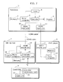
- FIG. 6 is a diagram showing the outline configuration of the remote control system in the first embodiment.
- FIG. 7 is a function block diagram of the remote control system in the first embodiment.
- a set top box 2 in the first embodiment is an example of the first video output apparatus
- a DVD player 1 is an example of the second video output apparatus
- a television 3 is an example of the video display apparatus.
- the remote control system includes the DVD player 1, the set top box 2, the television 3, and a controller 4.
- the DVD player 1 is a device which plays video content recorded on a DVD by decoding it, and outputting video and audio via the HDMI cable.
- the set top box 2 is a device which outputs video and audio of a cable television broadcast, via the HDMI cable.
- the television 3 is a device for outputting video and audio outputted from a device connected via the HDMI cable.
- the controller 4 is a device which transmits signals mainly to the set top box 2.
- the television 3 and the set top box 2 are connected by the HDMI cable, and the video and audio decoded by the set top box 2 are transmitted to the television 3 through the HDMI cable.
- the television 3 and the DVD player 1 are also connected by the HDMI cable, and the video and audio played back by the DVD player 1 are also transmitted to the television 3 in the same manner as with the set top box 2.
- the television 3, the set top box 2, and the DVD player 1 can transmit and receive CEC commands to and from each other via a CEC bus of the HDMI cable.
- the line of the CEC bus is included inside the tube of the HDMI cable together with the line for transmitting video and audio, and connection of the CEC bus is also carried out through the connection between devices using the HDMI cable.
- the television 3 is an example of the video display apparatus, and includes a display 5, a tuner 6, a memory 7, a microcomputer 8, a decoder 9, an HDMI input unit 10, and an HDMI input unit 11.
- the display 5 displays video, menus, and so on, obtained from the decoder 9.
- the microcomputer 8 interprets a CEC command and a command according to the operation of a controller of the television 3, and performs various processes. Furthermore, the microcomputer 8 also controls the decoder 9 and the tuner 6 as necessary.
- the tuner 6 receives a television broadcast wave received through an antenna not shown in the diagram and, for example, when the broadcast received is a digital broadcast, sends the data thereof to the decoder 9.
- the decoder 9 decodes video and audio from the broadcast wave obtained by the tuner 6, converts the result into an appropriate signal for displaying on the display 5, and sends the signal to the display 5. Furthermore, the decoder 9 also converts video obtained from the HDMI input unit 10, the HDMI input unit 11, and other external video inputs not shown in the diagram, into an appropriate signal for displaying on the display 5, and sends the signal to the display 5.
- the HDMI input unit 10 and the HDMI input unit 11 are connected to an HDMI output unit 19 of the set top box 2 and an HDMI output unit 14 of the DVD player 1, respectively, and receive an HDMI signal. Furthermore, together with the reception of HDMI signals, the HDMI input unit 10 and the HDMI input unit 11 perform the transmission and reception of CEC commands.
- a CEC unit of the HDMI input unit 10 and a CEC unit of the HDMI input unit 11 are bus-connected, and are respectively connected to the HDMI input unit 10 and the HDMI input unit 11 with respect to the set top box 2 and the DVD player 1. As such, mutual transmission and reception of CEC commands between the set top box 2 and the DVD player 1 is possible. Note that aside from the set top box 2 and the DVD player 1 in the present embodiment, electrical devices such as a DVD recorder or a video tape recorder can also be connected to the HDMI input unit 10 and the HDMI input unit 11.
- the DVD player 1 includes a microcomputer 12, a memory 13, and the HDMI output unit 14; reads a signal recorded on a DVD, using a DVD reading device not shown in the diagram; decodes video, still images, and audio; and outputs video and audio, as HDMI signals, through the HDMI output unit 14.
- the microcomputer 12 while using the memory 13: controls the DVD reading device not shown in the diagram; processes inputs from an input unit not shown in the diagram, included in the DVD player 1; and controls the HDMI output unit 14. Furthermore, the microcomputer 12 also instructs the decoding upon receiving a CEC command received by the HDMI output unit 14, and the outputting of a CEC command to the HDMI output unit 14.
- the HDMI output unit 14 outputs video and audio decoded by the DVD reading device, as HDMI signals, to the HDMI input unit 11. Furthermore, together with the transmission of HDMI signals, the HDMI output unit 14 also performs communication of CEC commands.
- the set top box 2 includes a controller reception unit 15, a microcomputer 16, a memory 17, a tuner 18, and the HDMI output unit 19.
- the microcomputer 16 while using the memory 17: controls the tuner 18; processes inputs from another input unit not shown in the diagram, included in the set top box 2; and controls the HDMI output unit 19. Furthermore, the microcomputer 16 also instructs, when the HDMI output unit 19 receives a CEC command, the decoding of the CEC command, and the outputting of a CEC command to the HDMI output unit 19. Furthermore, upon receiving a CEC command (called " ⁇ Active Source>") indicating the current outputting of video, the microcomputer 16 stores, in the memory 17, information identifying the transmission source device of the command.
- the HDMI output unit 19 outputs video and audio decoded by the DVD reading device, as HDMI signals, to the HDMI input unit 10. Furthermore, together with the transmission of HDMI signals, the HDMI output unit 19 also performs communication of CEC commands.
- the tuner 18 receives and decodes a cable television broadcast signal, and transmits video and audio to the HDMI output unit 19.
- the controller reception unit 15 receives a signal transmitted from the controller 4 through a wireless communication means such infrared rays and radio waves, and sends a result of the decoding of such signal to the microcomputer 16.
- the controller 4 includes a controller transmission unit 20 and an input unit 21.
- the input unit 21 is configured of any or a combination of, for example, a push button, a toggle switch, an arrow key, a joystick, and so on.
- the controller transmission unit 20 transmits a signal corresponding to the input obtained through the input unit 21, to the controller reception unit 15, using a wireless communication means such as infrared rays or radio waves.
- the signal corresponding to the button is transmitted by the controller transmission unit 20, received by the controller reception unit 15, and notified to the microcomputer 16 (step S201).
- the microcomputer 16 judges whether or not the signal received in step S201 is a signal of a key (hereafter called a “basic key") that is common to other devices, such as "UP”, “DOWN”, “LEFT”, “RIGHT”, and “ENTER” (step S202).
- a basic key a key that is common to other devices, such as "UP”, “DOWN”, “LEFT”, “RIGHT”, and “ENTER”
- step S201 In the case where it is judged that the signal received in step S201 is not a signal of a basic key and is a signal of a dedicated key for operating the set top box 2 (STB-dedicated key in step S202), the set top box 2 performs a process corresponding to the signal of such key (step S204).
- step S201 In the case where it is judged that the signal received in step S201 is a signal of a basic key (basic key in step S202), the microcomputer 16 refers to the memory 17 and checks for the last device that transmitted an ⁇ Active Source> command (step 5203).
- step S203 When the last device that transmitted the ⁇ Active Source> command is the set top box 2 (YES in step S203), the user is currently viewing the cable television broadcast received by the set top box 2, and thus the operation corresponding to the signal transmitted in step S201 is executed on the set top box 2 (step S204). With this, the user is able to use the functions included in the set top box 2 by using the controller 4. Furthermore, it is also possible for the microcomputer 16 to generate a Graphical User Interface (GUI), and for the user to operate a GUI menu included in the set top box 2 by operating the controller 4.
- GUI Graphical User Interface
- FIG. 9 is a flowchart showing the operation of the DVD player.
- the microcomputer 16 of the set top box 2 executes a program which activates the DVD player 1 and causes the start of playback. With the execution of the program, the microcomputer 16 of the set top box 2 transmits plural CEC commands for activating the DVD player 1 and starting playback.
- the DVD player 1 starts the playback of a DVD (step S103).
- the DVD player starts the playback (step S103).
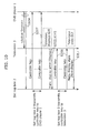
- the DVD player 1 broadcasts ⁇ Active Source> as a first command (step S104, FIG. 10 ).
- FIG. 11 is a flowchart showing the operation of the television.
- the television 3 receives the ⁇ Active Source> command (step S310), and switches the input to the terminal to which the DVD player 1 is connected. With this, the video outputted from the DVD player 1 is displayed on the television 3.
- FIG. 12 is a flowchart showing the operation of the set top box.
- the set top box 2 receives the ⁇ Active Source> command (step S210), and stores, in the memory 17, information indicating that the last transmission source of the command is the DVD player 1.
- FIG. 8 is a flowchart showing the operation of the set top box.
- step S201 when the user presses any of the buttons which are the input unit 21, the signal corresponding to the button is transmitted by the controller transmission unit 20, received by the controller reception unit 15, and notified to the microcomputer 16 (step S201).
- the microcomputer 16 judges whether or not the signal received in step S201 is a signal of a basic key (step S202).
- step S201 In the case where it is judged that the signal received in step S201 is a signal of a basic key (basic key in step S202), the microcomputer 16, in the same manner as when operating the set top box 2, refers to the memory 17 and checks whether or not the user is currently viewing the cable television broadcast received by the set top box 2 (step S203).
- the microcomputer 16 next, refers to the memory 17 and checks whether or not the television 3 is displaying the GUI menu (step S205).
- the microcomputer 16 refers to the memory 17 and assumes the last device that transmitted the ⁇ Active Source> to be the destination of the command (step S206).
- the microcomputer 16 transmits, as a second command, a command corresponding to the signal received in step S201, with the device (in this operation example, the DVD player 1: DVD player in step S206) indicated in step S206 as the transmission destination (step S207, FIG. 10 ).
- the DVD player 1 receives, via the television 3, the signal transmitted in step S207, and operates according to the command.
- the microcomputer 16 transmits the second command with the television 3 as the transmission destination (step S208, FIG. 10 ).
- the user is able to operate the DVD player 1 by using the controller 4.
- FIG. 8 is a flowchart showing the operation of the set top box.
- the signal corresponding to the button is transmitted from the controller transmission unit 20, received by the controller reception unit 15, and notified to the microcomputer 16 (step S201).
- an output video of the DVD player 1, a tuner screen of the television 3, or a tuner screen of the set top box 2 may be currently displayed on the display 5 of the television 3.
- the microcomputer 16 judges whether the signal received in step S201 is a signal of a basic key, a signal of a television menu display button, or the signal of a set top box-dedicated key (step S202). In the case where the received signal is a signal of a television menu display button (television menu display key in S202), the set top box 2 transmits, as a third command, a command instructing menu-display, with the television 3 as the destination (step 5209).
- FIG. 13 is a flowchart showing the operation of the television.
- step S320 Upon receiving the third command transmitted in step S209 (step S320), the television 3 displays a menu for operating the television 3, as shown in FIG. 14 (step S321).
- the television 3 transmits, as a fourth command, a command notifying the start of menu-display, with the set top box 2 as the destination (step S322, FIG. 10 ).
- FIG. 15 is a flowchart showing the operation of the set top box.
- the set top box 2 Upon receiving the fourth command transmitted in step S322 (step S220), the set top box 2 stores, in the memory 17, the fact that the television is currently displaying a menu (step S221).
- FIG. 8 is a flowchart showing the operation of the set top box.
- step S201 when the user presses a button which is the input unit 21, the signal corresponding to the button is transmitted by the controller transmission unit 20, received by the controller reception unit 15, and notified to the microcomputer 16 (step S201).
- the microcomputer 16 judges whether or not the key corresponding to the signal received in step S201 is a basic key (step S202).
- the microcomputer 16 refers to the memory 17 and judges whether or not the television is currently displaying a menu (step S205).
- the microcomputer 16 transmits, as the second command, a command corresponding to the basic key, with the television 3 as the destination (step S208, FIG. 10 ).
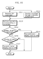
- FIG. 16 is a flowchart showing the operation of the television.
- step S311 When the television receives the command transmitted in step S208 (step S311), the television 3 carries out the operation of the menu, such as moving the cursor, according to the signal (step S313). Furthermore, in the case where the television 3 starts menu-display anew according to the operation in step S313, the television 3 transmits, to the set top box 2, a fourth command indicating the starting of the menu-display (step S315, FIG. 10 ).
- the television 3 transmits, as a fifth command, a command notifying the end of the menu-display, with the set top box 2 as the destination (step S317, FIG. 10 ).
- FIG. 17 is a flowchart showing the operation of the set top box.
- the set top box 2 Upon receiving the fifth command (step S230), the set top box 2 stores, in the memory 17, the fact that the television 3 is not currently displaying a menu (step S231).
- the set top box 2 identifies the last device that transmitted the ⁇ Active Source> which is the first command, or the command notifying the starting of menu-display which is the fourth command. Furthermore, the set top box 2 transmits, to the identified device, a command corresponding to the signal received from the controller 4. With this, the transmission of the same command to two or more devices is eliminated, and exclusive control of the device executing the command can be performed.
- the second embodiment includes, as is, the configuration and functions in the above-described first embodiment, configurations in the drawings that are the same as that in the first embodiment are given the same numerical reference and their description shall be omitted.
- FIG. 18 is a diagram showing the outline configuration of the remote control system in a second embodiment. Furthermore, FIG. 19 is a function block diagram of the remote control system in the second embodiment.
- the remote control system includes the DVD player 1, the set top box 2, the television 3, the controller 4, the AV amplifier 30, and an external speaker 31.
- the AV amplifier 30 is connected to the external speaker 31, and includes an HDMI output unit 32, a selector 33, an HDMI input unit 34, an amplifier 35, a microcomputer 36, and a memory 37.
- the selector 33 can select an HDMI signal to be outputted to the HDMI output unit 32, from between a signal that can be obtained from the HDMI input unit 34, and another video/audio input signal not shown in the diagram.
- a signal that can be obtained from the HDMI input unit 34 and another video/audio input signal not shown in the diagram.
- CEC bus included in the HDMI communication is possible regardless of which input is selected by the selector 33, and CEC command-based communication can also be carried out transparently from any HDMI-connected device.
- the HDMI input unit 10 of the television 3 and the HMDI output unit 19 of the set top box 2 are connected by an HDMI cable in the same manner as in the first embodiment. Furthermore, the television 3 and the HDMI output unit 32 of the AV amplifier are connected by an HDMI cable, and the DVD player 1 is connected to the HDMI input unit 34 of the AV amplifier by the HDMI cable.
- the audio of the DVD player 1 is transferred to the AV amplifier 30 through the HDMI cable. Since CEC is a bus connection, it is possible to connect devices, aside from the above-described connection, as long as it is within the scope allowed in the HDMI 1.2a standard.
- the user selects a button for "mode switching" which is a menu of the television 3.
- a mode switching program that is programmed into a ROM of the television 3 is executed.
- the remote control system performs the following series of operations.
- the television 3 transmits a CEC command to the AV amplifier 30, and checks whether or not the AV amplifier 30 is ON. In the case where the AV amplifier 30 is not ON, the television 3 transmits a command instructing the turning ON of power supply, to the AV amplifier 30.
- the television 3 mutes the built-in speaker and transmits, to the amplifier 30, a command instructing the outputting of the audio of a currently reproducing device from the external speaker 31.
- the audio of the DVD player 1 is outputted from the external speaker 31 connected to the AV amplifier 30.
- the present invention can be implemented, aside from the aforementioned embodiment, as long as the devices are connected to allow mutual communication.
- FIG. 20 is an external view of the remote control system in a third embodiment. Furthermore, FIG. 21 is function block diagram of the remote control system in the third embodiment.
- DVD player 1 and a DVD recorder 205 in the third embodiment are examples of the second video output apparatus
- the set top box 2 is an example of the first video output apparatus
- a television 203 is an example of the video display apparatus.
- the remote control system includes the DVD player 1, the set top box 2, the television 203, the controller 4, and the DVD recorder 205.
- the DVD player 1 is a device which decodes video content recorded on a DVD, and outputs video and audio via the HDMI cable.
- the set top box 2 is a device which outputs video and audio of a cable television broadcast, via the HDMI cable.
- the television 203 is a device for outputting video and audio outputted from a device connected via the HDMI cable.
- the controller 4 is a device which transmits a signal mainly to the set top box 2.
- the television 203 and the set top box 2 are connected by the HDMI cable, and the video and audio decoded by the set top box 2 are transmitted to the television 203 through the HDMI cable.
- the television 203 and the DVD player 1 are also connected by the HDMI cable, and the video and audio played back by the DVD player 1 are also transmitted to the television 3 in the same manner as with the set top box 2.
- the television 203, the set top box 2, and the DVD player 1 can transmit and receive CEC commands to and from each other via a CEC bus of the HDMI cable.
- the line of the CEC bus is included inside the tube of the HDMI cable together with the line for transmitting video and audio, and connection of the CEC bus is also carried out through the connection between devices using the HDMI cable.
- the television 203 is an example of the video display apparatus, and includes the display 5, the tuner 6, the memory 7, the microcomputer 8, the decoder 9, the HDMI input unit 10, an HDMI input unit 212, and the HDMI input unit 11.
- the display 5 displays video, menus, and so on, obtained from the decoder 9.
- the microcomputer 8 interprets a CEC command or a command according to the operation of a controller of the television 203, and performs various processes. Furthermore, the microcomputer 8 also controls the decoder 9 and the tuner 6 as necessary. Furthermore, the microcomputer 8 includes: a classification unit which classifies, based on the state of its own apparatus, whether or not a CEC command received from another apparatus via the CEC bus is a command addressed to its own apparatus; and a command execution unit which executes the CEC command received via the CEC bus in the case where the classification unit classifies the CEC command as a command addressed to its own apparatus, and which does not execute the command received through the CEC bus in the case where the CEC command is classified as a command addressed to another apparatus.
- a classification unit which classifies, based on the state of its own apparatus, whether or not a CEC command received from another apparatus via the CEC bus is a command addressed to its own apparatus
- a command execution unit which executes the CEC command received via the CEC bus in the case where the
- the tuner 6 receives a television broadcast wave received through an antenna not shown in the diagram and, when the broadcast received is a digital broadcast, for example, sends the data thereof to the decoder 9.
- the decoder 9 decodes video and audio from the broadcast wave obtained by the tuner 6, converts the result into an appropriate signal for displaying on the display 5, and sends the signal to the display 5. Furthermore, the decoder 9 also converts video obtained from the HDMI input unit 10, the HDMI input unit 212, the HDMI input unit 11, and other external video inputs not shown in the diagram, into an appropriate signal for displaying on the display 5, and sends the signal to the display 5.
- the HDMI input units 10, 211 and 11 are connected to the HDMI output unit 19 of the set top box 2, the HDMI output unit 14 of the DVD player 1, and an HDMI output unit 26 of the DVD recorder 205, respectively, and receive an HDMI signal. Furthermore, together with the reception of HDMI signals, the HDMI input units 10, 212, and 11 perform the transmission and reception of CEC commands.
- a CEC unit of the HDMI input units 10, 212, and 11 are bus-connected, and mutually transmit and receive CEC commands between the set top box 2, the DVD player 1, and the DVD recorder 205 connected to HDMI input units 10, 212, and 11.
- the DVD player 1 includes the microcomputer 12, the memory 13, and the HDMI output unit 14; reads a signal recorded on a DVD, using a DVD reading device not shown in the diagram; decodes video or still images, and audio; and outputs video and audio, as HDMI signals, through the HDMI output unit 14.
- the microcomputer 12 while using the memory 13: controls the DVD reading device not shown in the diagram; processes inputs from an input unit not shown in the diagram, included in the DVD player 1; and controls the HDMI output unit 14. Furthermore, the microcomputer 12 also instructs the decoding upon receiving a CEC command received by the HDMI output unit 14, and the outputting of a CEC command to the HDMI output unit 14.
- the microcomputer 12 includes: a notification unit which, at the time of operation of its own apparatus, instructs the outputting of a CEC command ⁇ Active Source> which is a state recognition command broadcasted to the set top box 2 and the television 203; a classification unit which classifies, based on the state of its own apparatus, whether or not a CEC command received from another apparatus via the CEC bus is a command addressed to its own apparatus; and a command execution unit which executes the CEC command received via the CEC bus in the case where the classification unit classifies the CEC command as a command addressed to its own apparatus, and which does not execute the command received through the CEC bus in the case where the CEC command is classified as a command addressed to another apparatus.
- a notification unit which, at the time of operation of its own apparatus, instructs the outputting of a CEC command ⁇ Active Source> which is a state recognition command broadcasted to the set top box 2 and the television 203
- a classification unit which classifies, based on the state of its own
- the HDMI output unit 14 outputs video and audio decoded by the DVD reading device, as HDMI signals, to the HDMI input unit 11. Furthermore, together with the transmission of HDMI signals, the HDMI output unit 14 also performs communication of CEC commands.
- the set top box 2 includes the controller reception unit 15, the microcomputer 16, the memory 17, the tuner 18, and the HDMI output unit 19.
- the microcomputer 16 while using the memory 17: controls the tuner 18; processes inputs from another input unit not shown in the diagram, included in the set top box 2; and controls the HDMI output unit 19. Furthermore, the microcomputer 16 also instructs, when the HDMI output unit 19 receives a command, the decoding of the CEC command, and the outputting of a CEC command to the HDMI output unit 19.
- the microcomputer 16 includes: a recognition unit which, upon receiving a CEC command ⁇ Active Source>, records the transmission source device of the command in the memory 17, and recognizes the operational state; a classification unit which classifies a command inputted with the controller 4; and a transfer unit which, in the case where the classification unit classifies that the command is a dedicated command for the television 203, transfers the dedicated command to the television 203 and, in the case where the command is classified as a common command that can be run commonly among plural devices connected to the CEC bus, transfers, via the CEC bus, to the television 203, and the DVD player 1 or the DVD recorder 205 which is in the operational state a command in which the common command is attached with a code indicating the television 203 as the transmission destination, and a command in which the common command is attached with a code having the DVD player 1 or the DVD recorder 205 which is in the operational state as the transmission destination, respectively.
- a recognition unit which, upon receiving a CEC command ⁇ Active Source>, records the transmission source
- the tuner 18 receives and decodes a cable television broadcast signal, and transmits video and audio to the HDMI output unit 19.
- the HDMI output unit 19 outputs video and audio decoded by the tuner 18, as HDMI signals, to the HDMI input unit 10. Furthermore, the HDMI output unit 19 also transmits and receives CEC commands.
- the controller reception unit 15 receives a signal transmitted from the controller 4 through a wireless communication means such infrared rays and radio waves, and sends a result of the decoding of such signal to the microcomputer 16.
- the controller 4 includes the controller transmission unit 20 and the input unit 21.
- the input unit 21 is configured of any or a combination of, for example, a push button, a toggle switch, an arrow key, a joystick, and so on.
- the controller transmission unit 20 transmits a signal corresponding to the input obtained through the input unit 21, to the controller reception unit 15, using a wireless communication means such as infrared rays or radio waves.
- the DVD recorder 205 includes the microcomputer 24, the memory 25, and the HDMI output unit 26; reads a signal recorded on a DVD, using a DVD reading device not shown in the diagram; decodes video or still images, and audio; and outputs video and audio, as HDMI signals, through the HDMI output unit 26.
- the microcomputer 24 includes: a notification unit which, at the time of operation of its own apparatus, instructs the outputting of a CEC command ⁇ Active Source> which is a state recognition command to the set top box 2 and the television 203; a classification unit which classifies, based on the state of its own apparatus, whether or not a CEC command received from another apparatus via the CEC bus is a command addressed to its own apparatus; and a command execution unit which executes the CEC command received via the CEC bus in the case where the classification unit classifies the CEC command as a command addressed to its own apparatus, and which does not execute the command received through the CEC bus in the case where the CEC command is classified as a command addressed to another apparatus.
- a notification unit which, at the time of operation of its own apparatus, instructs the outputting of a CEC command ⁇ Active Source> which is a state recognition command to the set top box 2 and the television 203
- a classification unit which classifies, based on the state of its own apparatus, whether or not
- the HDMI output unit 26 outputs video and audio decoded by the DVD reading device, as HDMI signals, to an HDMI input unit 212. Furthermore, together with the transmission of HDMI signals, the HDMI output unit 26 also performs communication of CEC commands.
- the set top box 2 receives information including a physical address by making an inquiry to the television 203, through DDC communication included in HDMI.
- the set top box 2 In the case where there is no reply even when DDC communication is attempted by the set top box 2, the set top box 2 assumes that the television is unconnected, and terminates the command transfer function according to the present invention. When successful in receiving the physical address, the set top box 2 transmits a ⁇ Polling Message> command with the logical address of the set top box as destination, establishes a logical address when there is no reply, and transmits a ⁇ Report Physical Address> command addressed to all the devices.
- the DVD player 1 and the DVD recorder 205 When connected with the television 203 by the HDMI cable, the DVD player 1 and the DVD recorder 205 receive information including a physical address by making an inquiry to the television 203, through DDC communication included in HDMI. When successful in receiving the physical address, the DVD player 1 and the DVD recorder 205 transmit a ⁇ Polling Message> command with the logical address of the respective devices as destinations, establish a logical address when there is no reply, and transmit a ⁇ Report Physical Address> command addressed to all the devices.
- the DVD player 1 and the DVD recorder 205 transmit a ⁇ Polling Message> command again to another logical address.
- the DVD player 1 and the DVD recorder 205 terminate functions with regard to CEC commands, and do not receive and transmit a CEC command until they are able to obtain a logical address through the changing of the connection configuration, and so on.
- the set top box 2 Upon receiving a ⁇ Report Physical Address> command, the set top box 2 records the transmission source device's logical address and physical address in the memory 17.
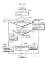
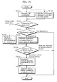
- step S241 when the user presses any of buttons which are the input unit 21 of the controller 4, the signal corresponding to the button is transmitted, received by the controller reception unit 15, notified to the microcomputer 16, and notified to the microcomputer 16 (step S241).
- the microcomputer 16 judges whether the key corresponding to the signal receiving in step S241 is a predetermined key that is common to other devices, such as "UP”, “DOWN, “LEFT”, “RIGT”, “ENTER”, and so on (hereafter called a “basic key”), a key which only operates on the television 203, or a key which only operates on the set top box 2 (step S242).
- the judgment of the signal received in step S241, in step 5242, is performed with reference to a table such as that shown in FIG. 23 .
- step S241 In the case where it is judged that the signal received in step S241 is a signal of a dedicated key for operating the set top box 2 (STB dedicated key in step S242), the set top box 2 performs the process corresponding to the signal of the key (step S243).
- the key received in step S241 is a key corresponding to a channel of a cable television broadcast
- the tuner 18 of the set top box 2 receives the set channel
- the HDMI output unit 19 outputs the video and audio of the channel.
- step S242 the microcomputer 16 refers to the memory 17 and checks for the last device that transmitted an ⁇ Active Source> command (hereafter called "active source device") (step S244).
- step 5244 the active source device is the set top box 2 (STB in step S244)
- the set top box 2 transmits a CEC command corresponding to the signal received in step S241 to the television 203 (step S245), and the operation corresponding to the signal is also executed by the set top box 2.
- step S242 when the set top box 2 is not displaying a menu, the set top box 2 does not execute the operation corresponding to the signal.
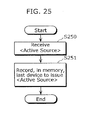
- the signal received in step S241 is a signal which only operates on the set top box, and is a signal which activates a menu built-into the set top box 2 or a signal instructing the viewing of a cable television broadcast received by the set top box 2, the set top box 2 transmits an ⁇ Active Source> command.
- the user can operate the set top box 2 in the present remote control system, by using the controller 4.
- the signal corresponding to the button is transmitted by the controller transmission unit 20, received by the controller reception unit 15, and notified to the microcomputer 16 (step S241).
- step S241 the output video of the DVD player 1, the tuner screen of the television 203, or the tuner screen of the set top box 2 may be currently displayed on the display 5.
- the set top box 2 judges whether the signal received in step S241 is a signal of a basic key, a signal of a television menu display button, or the signal of a set top box-dedicated key (step S242). In the case where the received signal is a signal of the television menu display button (television menu display key in S242), the set top box 2 transmits a command instructing television menu-display, with the television 203 as the destination (step S248, FIG. 24 ).
- the set top box 2 which receives the transmitted ⁇ Active Source> command (step S250), stores, in the memory 17, the logical address of the device which is the transmission source of the command, as information indicating the current transmission source device (step S251).
- the set top box 2 refers to the memory 17 for the device which is the active source device (step S244).
- step S246 In the case where the active source device is neither the set top box 2 nor the television 203 (neither STB nor television in step S244), for example, the case where the active source device is the DVD player 1, the set top box 2 transmits a CEC command to the DVD player 1, which is the active source device, and the television 203 (step 5246, FIG. 24 ).
- the two commands transmitted in step S246, though having different destination devices, are commands with the same operating code and operand. However, since devices other than the television 203 and the DVD player 1 are not included in the destination, the commands have absolutely no effect on the other devices.
- the set top box 2 refers to the table shown in FIG. 23 , and determines the CEC command corresponding to the signal received in step S241.
- step S244 When, in step S244, the active source device is the television 203 (television in step S244), the controller 4 refers to the table shown in FIG. 23 and transmits a CEC command corresponding to the signal received in step S241 to the television 203 (step S247).
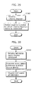
- FIG. 26 is a flowchart showing the operation of the DVD player 1 and the DVD recorder 205.
- the user while looking at a menu generated by the microcomputer 16 of the set top box 2 as shown in FIG. 27 for example, can move the item indicated by the cursor 42 and execute a desired program built-into the set top box 2 by operating the controller 4.
- a desired program built-into the set top box 2 by operating the controller 4.
- the microcomputer 16 of the set top box 2 executes a program which activates the DVD player 1 and starts the playback of a DVD.
- a command instructing the turning of power ON and a command for starting the playback of the DVD are transmitted to the DVD player 1 as CEC commands.
- step S111 Upon receiving the CEC commands (step S111), the DVD player 1 judges whether or not the commands received in step S111 are commands of a basic key (step S113).
- step S111 In the case where the commands received in step S111 are commands other than those of a basic key (other than basic key in step S113), the DVD player executes the operation corresponding to the commands (step S115).
- step S115 the command received in step S111 is, for example, the command instructing the turning of the power ON
- the DVD player 1 shifts from a stand-by state to a power ON state. Furthermore, in the case where the command received in step S111 is the command for starting the playback of the DVD, the DVD player 1 starts the playback of the DVD.
- the DVD player 1 upon receiving a signal from an input unit of the DVD player 1, which is not shown in the diagram (step S112), the DVD player 1 operates, in response to the signal received in step S112, in the same manner as when receiving the command in step S111.
- the signal received in step S112 is a signal instructing the playback of the DVD
- the DVD player 1 starts the playback of the DVD in the same manner in step S115.
- step S115 or step S116 judges whether the operation in step S115 or step S116 is an operation for becoming an active source.
- An "operation for becoming an active source” is an operation programmed beforehand in the DVD player 1, in which a source device starts the output of video and audio according to the operation by the user. For example, there is the operation to start the playback of a DVD, or the operation to start the display of a menu of a DVD.
- the DVD player 1 In the case where the DVD player 1 needs to become an active source device (become an active source in step S118), the DVD player 1 broadcasts an ⁇ Active Source> command to all devices connected by the CEC bus.
- the television 3 receiving the ⁇ Active Source> command switches the video and audio input to the terminal to which the DVD player 1 is connected.
- step S119, FIG. 24 When the DVD player 1 broadcasts the ⁇ Active Source> (step S119, FIG. 24 ), when the user presses a button which is a basic key of the controller 4, a command corresponding to the basic key is transmitted from the set top box 2, with the DVD player 1 as the destination.
- the DVD player 1 transmits a CEC command instructing menu deletion, to the television 203 (step S120).
- the DVD player operates in the following manner in the case of receiving a command corresponding to a basic key.
- step S111 In the case where the command received in step S111 is judged as a basic key in step S113 (basic key in step S113), the DVD player 1 refers to the memory 13 and checks whether or not the DVD player 1 is displaying a menu (step S114).
- step S114 In the case where the DVD player 1 is not displaying a menu in step S114 (not displaying in step S114), the process ends without any particular operation being carried out (step S117).
- the DVD player 1 performs the operation corresponding to the command (step S116). For example, in the case where the received command is a command corresponding to the UP key included in the basic keys, the DVD player 1 moves the cursor for the menu generated by the microcomputer 12 one item up. Furthermore, for example, in the case where the received command is for the ENTER key included in the basic keys, the DVD player 1 executes the function corresponding to the item on which the cursor for the menu generated by the microcomputer 12 is focused.
- FIG. 22 is a flowchart showing the operation of the set top box 2.
- FIG. 28 to FIG. 30 are flowcharts showing the operation of the television 203.
- the television 203 Upon receiving an ⁇ Active Source> command as shown in FIG. 29 (step S340), the television 203 records, in the memory 7, the device which is the transmission source of the command, as the active source device, shifts the input to the input terminal to which the active source device is connected, and displays the video supplied by the active source device, on the display 5 (step S341).
- the television 203 operates in the following manner.
- the television 203 upon receiving a command instructing the display of a television menu, transmitted from the set top box 2 in step 5248 (step S350), the television 203 refers to the memory 7 for the active source device, and transmits a CEC command instructing menu deletion, to the active source device (step S351, FIG. 24 ).
- the display 5 displays a menu generated by the microcomputer 8 such as that shown in FIG. 14 , for example, by superimposition on the video currently being inputted (step S352, FIG. 24 ).
- the set top box 2 transmits CEC commands to the DVD player 1 which is the active source device, and to the television 203, in the same manner as in the operation described previously (step S246, FIG. 24 ).
- the television 203 operates in the following manner in the case of receiving a command corresponding to a basic key (step S331).
- step S311 In the case where the command received in step S311 is judged as a basic key in step S333 (basic key in step S333), the television 203 refers to the memory 7 and checks whether or not the television 203 is displaying a menu (step S335).
- the television 203 performs the operation corresponding to the command (step S336).
- the television 203 moves the cursor for the menu generated by the microcomputer 8 one item up.
- the television 203 executes the function corresponding to the item on which the cursor for the menu generated by the microcomputer 8 is focused.
- step S334 the television 203 executes the operation corresponding to the command (step S334).
- the user can also operate the DVD recorder 205 using the controller 4, in the same manner as the DVD player 1.
- the user When the user is viewing the cable television broadcast received by the set top box, on the television 203, the user selects an item for operating the DVD recorder 205, such as an item displayed as "Operate DVD recorder" for example, by moving the cursor 42 of the menu 41 of the set top box 2 shown in FIG. 27 , up and down using the controller 4, in the same manner as when operating the DVD player 1.
- the microcomputer 16 of the set top box 2 transmits a CEC command for activating the DVD recorder 205, and transmits a CEC command instructing the start of DVD playback to the DVD recorder 205.
- the DVD recorder 205 Upon receiving a CEC command other than that of a basic key (other than basic key in step S113), the DVD recorder 205 receiving the CEC command performs the operation corresponding to the command, in the same manner as the DVD player 1 (step S115).
- the user starts the playback of a DVD by operating a controller of the DVD recorder 205, which is not shown in the diagram (other than basic key in step S112 and step S113; and step S115).
- step S115 Since the DVD recorder 205 becomes the active source when the playback is started in the operation in step S115 or step S116 (active source in step S118), the DVD recorder 205 broadcasts an ⁇ Active Source> command (step S119, FIG. 24 ).
- the television 3 receiving the ⁇ Active Source> command switches the video and audio input to the terminal to which the DVD recorder 205 is connected (step S341).
- the set top box 2 which receives the ⁇ Active Source> command issued in step S119 step S250
- stores, in the memory 17, the logical address of the device which is the transmission source of the command step S251).
- a command corresponding to the basic key is transmitted from the set top box 2.
- the DVD recorder 205 judges that the command is that of a basic key (basic key in step S113) and the DVD recorder 205 is displaying a menu, in the same manner as the DVD player 1 (displaying in step S114), the DVD recorder 205 performs the process corresponding to the command, in the same manner as the DVD player 1 (step S115).
- the set top box 2 transmits a command to the two devices, namely the television 203 and the active source; the television 203, the DVD player 1, and the DVD recorder 205 each judge, based on the state of their own apparatus, whether or not to execute the command transmitted from the set top box 2; and the command is executed only by the device which judges that it should execute the command. For example, the device which is currently displaying a menu executes the command, and the other devices do not execute the command.
- the device which is currently displaying a menu transmits a CEC command instructing menu deletion. With this, the execution of the same command by two or more devices is eliminated, and thus it is possible to carry out the exclusive control of the device executing the command.
- the present invention can be applied in a remote control system, and so on, in which plural devices, including a set top box, are connected through an HDMI cable.
Landscapes
- Engineering & Computer Science (AREA)
- Multimedia (AREA)
- Signal Processing (AREA)
- Physics & Mathematics (AREA)
- General Physics & Mathematics (AREA)
- Computer Networks & Wireless Communication (AREA)
- Human Computer Interaction (AREA)
- Selective Calling Equipment (AREA)
- Two-Way Televisions, Distribution Of Moving Picture Or The Like (AREA)
- Details Of Television Systems (AREA)
Applications Claiming Priority (3)
| Application Number | Priority Date | Filing Date | Title |
|---|---|---|---|
| JP2006332518A JP4143102B2 (ja) | 2006-12-08 | 2006-12-08 | リモートコントロールシステム |
| JP2007056444A JP4143675B1 (ja) | 2007-03-06 | 2007-03-06 | リモートコントロールシステムおよびコマンド転送方法 |
| PCT/JP2007/073665 WO2008069304A1 (ja) | 2006-12-08 | 2007-12-07 | リモートコントロールシステム |
Publications (2)
| Publication Number | Publication Date |
|---|---|
| EP2091228A1 true EP2091228A1 (de) | 2009-08-19 |
| EP2091228A4 EP2091228A4 (de) | 2012-12-19 |
Family
ID=39492179
Family Applications (1)
| Application Number | Title | Priority Date | Filing Date |
|---|---|---|---|
| EP07859743A Withdrawn EP2091228A4 (de) | 2006-12-08 | 2007-12-07 | Fernsteuerungssystem |
Country Status (3)
| Country | Link |
|---|---|
| US (1) | US7554614B2 (de) |
| EP (1) | EP2091228A4 (de) |
| WO (1) | WO2008069304A1 (de) |
Cited By (1)
| Publication number | Priority date | Publication date | Assignee | Title |
|---|---|---|---|---|
| CN104661069A (zh) * | 2015-03-16 | 2015-05-27 | 深圳市彩易生活科技有限公司 | 一种电视控制方法、系统及相关设备 |
Families Citing this family (58)
| Publication number | Priority date | Publication date | Assignee | Title |
|---|---|---|---|---|
| TWI266534B (en) * | 2005-07-29 | 2006-11-11 | Optoma Corp | Control system for synchronously controlling displaying apparatus and playing apparatus |
| US7907222B2 (en) | 2005-09-08 | 2011-03-15 | Universal Electronics Inc. | System and method for simplified setup of a universal remote control |
| US11769398B2 (en) | 2005-09-08 | 2023-09-26 | Universal Electronics Inc. | System and method for widget-assisted setup of a universal remote control |
| JP4172498B2 (ja) * | 2006-05-16 | 2008-10-29 | ソニー株式会社 | 伝送システム、伝送方法、映像出力装置及び映像入力装置 |
| JP5186732B2 (ja) * | 2006-05-19 | 2013-04-24 | 船井電機株式会社 | テレビジョン受像機 |
| US20070298656A1 (en) * | 2006-06-22 | 2007-12-27 | Good Mind Industries Co., Ltd. | Switch apparatus for multiple high definition multimedia interface sources |
| JP4020162B1 (ja) * | 2006-07-27 | 2007-12-12 | オンキヨー株式会社 | 映像音声再生装置 |
| US8812629B2 (en) | 2008-04-18 | 2014-08-19 | Universal Electronics Inc. | System and method for configuring the remote control functionality of a portable device |
| US9208679B2 (en) | 2006-09-05 | 2015-12-08 | Universal Electronics Inc. | System and method for configuring the remote control functionality of a portable device |
| US8659400B2 (en) | 2006-09-05 | 2014-02-25 | Universal Electronics Inc. | System and method for configuring the remote control functionality of a portable device |
| US8760582B2 (en) * | 2006-10-16 | 2014-06-24 | Sony Corporation | Method for selecting an input media source |
| WO2008056707A1 (fr) | 2006-11-07 | 2008-05-15 | Sony Corporation | Dispositif électronique, procédé de transmission d'informations de commande et procédé de réception d'informations de commande |
| US9083914B2 (en) * | 2007-12-27 | 2015-07-14 | Echostar Technologies Corporation | Electronic system informing a first electronic device of user remote control activity involving a second electronic device |
| US9088663B2 (en) | 2008-04-18 | 2015-07-21 | Universal Electronics Inc. | System for appliance control via a network |
| US9852615B2 (en) | 2011-03-25 | 2017-12-26 | Universal Electronics Inc. | System and method for facilitating appliance control via a smart device |
| US9350850B2 (en) * | 2008-04-18 | 2016-05-24 | Uei Cayman Inc. | Using HDMI-CEC to identify a codeset |
| JP4766073B2 (ja) * | 2008-05-30 | 2011-09-07 | ソニー株式会社 | 情報処理装置および情報処理方法 |
| JP5171428B2 (ja) * | 2008-06-25 | 2013-03-27 | 三洋電機株式会社 | 電子機器 |
| JP5159489B2 (ja) * | 2008-07-18 | 2013-03-06 | キヤノン株式会社 | 通信装置 |
| JP2010041203A (ja) * | 2008-08-01 | 2010-02-18 | Sharp Corp | 表示装置 |
| JP5262526B2 (ja) * | 2008-09-30 | 2013-08-14 | 株式会社Jvcケンウッド | 映像音声再生システム、av増幅装置およびプログラム |
| JP2010098699A (ja) * | 2008-10-20 | 2010-04-30 | Canon Inc | 受信装置、及びその制御方法 |
| WO2010047123A1 (ja) * | 2008-10-24 | 2010-04-29 | パナソニック株式会社 | Bd再生システム、bd再生装置、表示装置及びコンピュータプログラム |
| EP2192573B1 (de) * | 2008-11-26 | 2020-12-30 | Samsung Electronics Co., Ltd. | Vorrichtungsanzeige mit externer Geräteverbindungseinheit und Verfahren zur Bestimmung des Formats des Eingabebildes dafür |
| JP2010193247A (ja) * | 2009-02-19 | 2010-09-02 | Sanyo Electric Co Ltd | Hdmi機器 |
| JP5428779B2 (ja) * | 2009-02-24 | 2014-02-26 | 株式会社Jvcケンウッド | 放送受信装置 |
| US20100245667A1 (en) * | 2009-03-24 | 2010-09-30 | Sony Corporation | Non-standalone tv pc |
| WO2011019155A2 (en) * | 2009-08-14 | 2011-02-17 | Lg Electronics Inc. | Remote control device and remote control method using the same |
| US8218090B2 (en) * | 2009-09-17 | 2012-07-10 | Sony Corporation | Integrated user interface and control in HDMI/CEC |
| WO2011040152A1 (ja) * | 2009-09-29 | 2011-04-07 | シャープ株式会社 | 周辺機器情報表示システム、表示装置、及び周辺機器 |
| CN102577362B (zh) * | 2009-09-29 | 2014-12-31 | 夏普株式会社 | 周边设备控制系统、显示装置及周边设备 |
| TW201119377A (en) * | 2009-11-25 | 2011-06-01 | Novatek Microelectronics Corp | Control method of prompt facility in HDMI-CEC devic and display apparatus with such control method |
| US9310887B2 (en) * | 2010-05-06 | 2016-04-12 | James W. Wieder | Handheld and wearable remote-controllers |
| US9436219B2 (en) | 2010-05-12 | 2016-09-06 | Litl Llc | Remote control to operate computer system |
| US8938753B2 (en) * | 2010-05-12 | 2015-01-20 | Litl Llc | Configurable computer system |
| WO2011145701A1 (ja) * | 2010-05-19 | 2011-11-24 | シャープ株式会社 | ソース機器、シンク機器、システム、プログラム、及び、記録媒体 |
| JP5460530B2 (ja) * | 2010-09-06 | 2014-04-02 | 日立コンシューマエレクトロニクス株式会社 | 表示システム、表示装置、及び中継装置 |
| JP5585370B2 (ja) * | 2010-10-12 | 2014-09-10 | オンキヨー株式会社 | コマンド情報告知装置及びそのプログラム |
| JP2012119839A (ja) * | 2010-11-30 | 2012-06-21 | Funai Electric Co Ltd | 映像表示機器 |
| JP5259750B2 (ja) * | 2011-01-31 | 2013-08-07 | 株式会社ソニー・コンピュータエンタテインメント | リモートコントローラおよびその発光部点灯制御方法 |
| US20120226981A1 (en) * | 2011-03-02 | 2012-09-06 | Microsoft Corporation | Controlling electronic devices in a multimedia system through a natural user interface |
| JP2012248257A (ja) * | 2011-05-31 | 2012-12-13 | Funai Electric Co Ltd | 映像音声機器、及びそれを備える映像音声システム |
| US9019435B2 (en) | 2011-09-22 | 2015-04-28 | Universal Electronics Inc. | System and method for configuring controlling device functionality |
| US8971546B2 (en) | 2011-10-14 | 2015-03-03 | Sonos, Inc. | Systems, methods, apparatus, and articles of manufacture to control audio playback devices |
| US11295603B2 (en) * | 2011-10-28 | 2022-04-05 | Universal Electronics Inc. | System and method for optimized appliance control |
| US11756412B2 (en) | 2011-10-28 | 2023-09-12 | Universal Electronics Inc. | Systems and methods for associating services and/or devices with a voice assistant |
| US9449500B2 (en) | 2012-08-08 | 2016-09-20 | Universal Electronics Inc. | System and method for optimized appliance control |
| US10937308B2 (en) | 2011-10-28 | 2021-03-02 | Universal Electronics Inc. | System and method for optimized appliance control |
| US20130173835A1 (en) * | 2011-12-29 | 2013-07-04 | Broadcom Corporation | Controlling HDMI Devices Via Intelligent Emulation of Consumer Electronics Control (CEC) Protocol |
| JP2014075094A (ja) | 2012-10-05 | 2014-04-24 | Funai Electric Co Ltd | 表示装置、表示システム、携帯情報端末および表示装置の制御方法 |
| CA2909570C (en) * | 2013-04-16 | 2022-08-16 | Home Control Singapore Pte. Ltd. | Remote control for first and second apparatus |
| CN103391470A (zh) * | 2013-07-10 | 2013-11-13 | Tcl通力电子(惠州)有限公司 | 自动切换信源的方法及其装置 |
| WO2016081636A1 (en) | 2014-11-18 | 2016-05-26 | Branch Media Labs, Inc. | Seamless setup and control for home entertainment devices and content |
| TWI619387B (zh) * | 2015-08-14 | 2018-03-21 | 凱銳光電股份有限公司 | 符合hdmi-cec規格的遙控方法與系統 |
| JP2018101828A (ja) * | 2016-12-19 | 2018-06-28 | 船井電機株式会社 | 制御装置 |
| WO2018148439A1 (en) | 2017-02-10 | 2018-08-16 | Caavo Inc | Determining state signatures for consumer electronic devices coupled to an audio/video switch |
| CN111314758A (zh) * | 2020-02-28 | 2020-06-19 | 四川长虹电器股份有限公司 | 多设备遥控方法与遥控装置 |
| CN116170620B (zh) * | 2023-02-03 | 2026-04-14 | 海宁奕斯伟计算技术有限公司 | 源设备反向控制装置、方法、源设备、系统及存储介质 |
Family Cites Families (15)
| Publication number | Priority date | Publication date | Assignee | Title |
|---|---|---|---|---|
| GB9121203D0 (en) * | 1991-10-04 | 1991-11-20 | D2B Systems Co Ltd | Local communication bus system and apparatus for use in such a system |
| JP3198486B2 (ja) | 1992-03-11 | 2001-08-13 | ソニー株式会社 | Avシステムのモニタ装置 |
| JP3611588B2 (ja) * | 1992-12-21 | 2005-01-19 | ソニー株式会社 | 送信方法、受信方法、通信方法及び双方向バスシステム |
| JP3309720B2 (ja) * | 1996-06-25 | 2002-07-29 | ソニー株式会社 | 映像システムの制御方法 |
| US5991842A (en) * | 1996-08-27 | 1999-11-23 | Canon Kabushiki Kaisha | Communication system for providing digital data transfer, electronic equipment for transferring data using the communication system, and an interface control device |
| FR2777140A1 (fr) * | 1998-04-07 | 1999-10-01 | Philips Electronics Nv | Systeme audiovisuel constitue de plusieurs appareils dont certains sont constitues de plusieurs modules fonctionnels |
| JP2000059459A (ja) | 1998-08-11 | 2000-02-25 | Canon Inc | データ通信装置、データ通信システム、データ通信方法、及び記憶媒体 |
| JP2000124930A (ja) | 1998-10-19 | 2000-04-28 | Sony Corp | データ伝送制御装置及びデータ伝送方法 |
| JP2002215483A (ja) * | 2001-01-15 | 2002-08-02 | Matsushita Electric Ind Co Ltd | 機器制御システム並びに、機器制御システムにおけるコントローラ及びデバイス |
| US20020194596A1 (en) * | 2001-06-18 | 2002-12-19 | Srivastava Gopal K. | Control of multiple AV-devices by a single master controller using infrared transmitted commands and bus transmitted commands |
| US20030093804A1 (en) * | 2001-11-13 | 2003-05-15 | Chang Matthew S. | Seamless integration of multiple data/internet connections |
| KR100475447B1 (ko) * | 2002-01-21 | 2005-03-10 | 엘지전자 주식회사 | 셋탑 박스를 가진 영상표시기기의 입력신호 처리방법 및장치 |
| JP4385099B2 (ja) * | 2003-12-03 | 2009-12-16 | 株式会社日立製作所 | 放送受信装置及びストリーム出力装置 |
| US20050132055A1 (en) * | 2003-12-12 | 2005-06-16 | Raja Neogi | System and method to control appliances using adaptive interfaces |
| US20060084409A1 (en) * | 2004-10-15 | 2006-04-20 | Muffaddal Ghadiali | Systems for and methods of programming a remote control |
-
2007
- 2007-12-07 US US12/282,024 patent/US7554614B2/en not_active Expired - Fee Related
- 2007-12-07 WO PCT/JP2007/073665 patent/WO2008069304A1/ja not_active Ceased
- 2007-12-07 EP EP07859743A patent/EP2091228A4/de not_active Withdrawn
Cited By (1)
| Publication number | Priority date | Publication date | Assignee | Title |
|---|---|---|---|---|
| CN104661069A (zh) * | 2015-03-16 | 2015-05-27 | 深圳市彩易生活科技有限公司 | 一种电视控制方法、系统及相关设备 |
Also Published As
| Publication number | Publication date |
|---|---|
| US20090051824A1 (en) | 2009-02-26 |
| EP2091228A4 (de) | 2012-12-19 |
| US7554614B2 (en) | 2009-06-30 |
| WO2008069304A1 (ja) | 2008-06-12 |
Similar Documents
| Publication | Publication Date | Title |
|---|---|---|
| EP2091228A1 (de) | Fernsteuerungssystem | |
| CN101395902B (zh) | 遥控系统 | |
| US8773360B2 (en) | Display device, two-way communication system and display information using method | |
| US20090089675A1 (en) | Method for providing graphical user interface and video apparatus using the same | |
| US7810129B2 (en) | Video display apparatus and reproduction apparatus | |
| US9277267B2 (en) | Content output system, information display apparatus, content output apparatus, and content information display method | |
| US20020040474A1 (en) | Video processing device | |
| US20090147140A1 (en) | Image apparatus for processing plurality of images and control method thereof | |
| KR20230093212A (ko) | 디스플레이 장치 및 그 동작 방법 | |
| US7017177B1 (en) | Digital broadcasting receiver and method of controlling the same | |
| JP4143675B1 (ja) | リモートコントロールシステムおよびコマンド転送方法 | |
| US20090219452A1 (en) | Electronic apparatus and display control method | |
| JP2008219932A (ja) | リモートコントロールシステムおよびコマンド転送方法 | |
| CN101273620A (zh) | 使用操作界面的机器控制方法及使用该方法的电子机器和系统 | |
| JP4013937B2 (ja) | Ieee1394シリアルバスに接続されるディジタルテレビジョン受像機、及びieee1394シリアルバスに接続されるコントローラ機器 | |
| JP2008079125A (ja) | 映像表示システム、映像表示システムを構成するメイン装置およびサブ装置 | |
| JP2008072419A (ja) | Av機器接続装置、テレビジョン受像機およびavシステム | |
| US20080284913A1 (en) | Audio-visual system, reproducing apparatus, and display device | |
| JP5082562B2 (ja) | デジタル放送受信方法及び装置 | |
| KR101300949B1 (ko) | 영상표시기기를 이용한 외부기기의 제어방법 | |
| JP2007110391A (ja) | 放送受信機 | |
| JP5157423B2 (ja) | 録画制御方法、録画システム、視聴装置、及び録画装置 | |
| US20040184790A1 (en) | Video reproduction apparatus | |
| KR101485602B1 (ko) | 영상표시 시스템 및 그 제어 방법 | |
| JP2006013564A (ja) | リモートコントローラ、制御方法、映像出力装置、映像出力方法、映像出力システム |
Legal Events
| Date | Code | Title | Description |
|---|---|---|---|
| PUAI | Public reference made under article 153(3) epc to a published international application that has entered the european phase |
Free format text: ORIGINAL CODE: 0009012 |
|
| 17P | Request for examination filed |
Effective date: 20090302 |
|
| AK | Designated contracting states |
Kind code of ref document: A1 Designated state(s): AT BE BG CH CY CZ DE DK EE ES FI FR GB GR HU IE IS IT LI LT LU LV MC MT NL PL PT RO SE SI SK TR |
|
| RBV | Designated contracting states (corrected) |
Designated state(s): AT BE BG CH CY CZ DE DK EE ES FI FR GB GR HU IE IS IT LI LT LU LV MC MT NL PL PT RO SE SI SK TR |
|
| DAX | Request for extension of the european patent (deleted) | ||
| A4 | Supplementary search report drawn up and despatched |
Effective date: 20121119 |
|
| RIC1 | Information provided on ipc code assigned before grant |
Ipc: H04Q 9/00 20060101ALI20121113BHEP Ipc: H04N 5/00 20110101AFI20121113BHEP Ipc: G08C 23/04 20060101ALI20121113BHEP Ipc: H04N 5/44 20110101ALI20121113BHEP |
|
| STAA | Information on the status of an ep patent application or granted ep patent |
Free format text: STATUS: THE APPLICATION IS DEEMED TO BE WITHDRAWN |
|
| 18D | Application deemed to be withdrawn |
Effective date: 20130618 |