EP2091233A2 - Abbildungsvorrichtung - Google Patents
Abbildungsvorrichtung Download PDFInfo
- Publication number
- EP2091233A2 EP2091233A2 EP09250322A EP09250322A EP2091233A2 EP 2091233 A2 EP2091233 A2 EP 2091233A2 EP 09250322 A EP09250322 A EP 09250322A EP 09250322 A EP09250322 A EP 09250322A EP 2091233 A2 EP2091233 A2 EP 2091233A2
- Authority
- EP
- European Patent Office
- Prior art keywords
- imaging apparatus
- evaluation
- image
- orientation
- camera
- Prior art date
- Legal status (The legal status is an assumption and is not a legal conclusion. Google has not performed a legal analysis and makes no representation as to the accuracy of the status listed.)
- Granted
Links
- 238000003384 imaging method Methods 0.000 title claims abstract description 45
- 238000011156 evaluation Methods 0.000 claims abstract description 72
- 230000001133 acceleration Effects 0.000 claims description 10
- 230000001419 dependent effect Effects 0.000 claims 1
- SDJLVPMBBFRBLL-UHFFFAOYSA-N dsp-4 Chemical compound ClCCN(CC)CC1=CC=CC=C1Br SDJLVPMBBFRBLL-UHFFFAOYSA-N 0.000 description 12
- 230000003287 optical effect Effects 0.000 description 8
- 238000012545 processing Methods 0.000 description 7
- 238000000034 method Methods 0.000 description 4
- 238000001514 detection method Methods 0.000 description 3
- 238000012937 correction Methods 0.000 description 2
- 238000010586 diagram Methods 0.000 description 2
- 238000012790 confirmation Methods 0.000 description 1
- 230000003247 decreasing effect Effects 0.000 description 1
- 238000012544 monitoring process Methods 0.000 description 1
- 238000005070 sampling Methods 0.000 description 1
- 239000007787 solid Substances 0.000 description 1
Images


Classifications
-
- H—ELECTRICITY
- H04—ELECTRIC COMMUNICATION TECHNIQUE
- H04N—PICTORIAL COMMUNICATION, e.g. TELEVISION
- H04N23/00—Cameras or camera modules comprising electronic image sensors; Control thereof
- H04N23/60—Control of cameras or camera modules
- H04N23/67—Focus control based on electronic image sensor signals
- H04N23/673—Focus control based on electronic image sensor signals based on contrast or high frequency components of image signals, e.g. hill climbing method
-
- H—ELECTRICITY
- H04—ELECTRIC COMMUNICATION TECHNIQUE
- H04N—PICTORIAL COMMUNICATION, e.g. TELEVISION
- H04N25/00—Circuitry of solid-state image sensors [SSIS]; Control thereof
- H04N25/40—Extracting pixel data from image sensors by controlling scanning circuits, e.g. by modifying the number of pixels sampled or to be sampled
- H04N25/42—Extracting pixel data from image sensors by controlling scanning circuits, e.g. by modifying the number of pixels sampled or to be sampled by switching between different modes of operation using different resolutions or aspect ratios, e.g. switching between interlaced and non-interlaced mode
Definitions
- the present invention relates to an imaging apparatus capable of rapidly performing an AF control regardless of the orientation of the imaging apparatus when photographing.
- AF processing has been required in an imaging apparatus such as a digital camera ("camera” hereinafter).
- the known conventional AF is performed by obtaining an AF evaluation value which is contrast data of image signals output from an image pickup device, and controlling a focal position of an optical system when the AF evaluation value achieves a peak.
- image signals output from the image pickup device for generating an AF evaluation value are read-out in a horizontal direction ("horizontal reading direction” hereinafter) in relation to the subject.
- a direction for example, a longitudinal direction
- the image signals are read-out in the direction ("vertical reading direction” hereinafter) substantially perpendicular to the subject image.
- most of the subject images have vertical stripes, that is, most of the subject images have strong contrast in a horizontal direction, and a gradient of the AF evaluation value obtained by reading-out image signals of such a subject image in the horizontal reading direction is normally sufficiently large to rapidly determine a peak of the AF evaluation values.
- the gradient of the AF evaluation values obtained by reading image signals of such a subject image in the vertical reading direction is not sufficient enough to rapidly determine the peak of the AF evaluation values. That is, the AF control when photographing in the vertical state is more slowly performed than the AF control when photographing in the horizontal state.
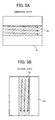
- FIGs.5A and 5B schematically show the relationship between the image signals and the reading direction depending on the orientation of the camera.
- FIGs.6A and 6B schematically show the relationship between the reading direction and the change of the generated AF evaluation value depending on the orientation of the camera.
- reference number 5a indicates an entire area of the image signals from the image pickup device and reference number 5b indicates a partial area of the entire area 5a of the image signals, which is to be focused, that is, a read-out area of the image signals used for generating an AF evaluation value.
- the read-out area 5b can be optionally set in the entire area 5a and it is preferable to set the read-out area 5b to an area including a center of the image, that is, a center of the entire area 5a, as shown in FIGs 5A and 5B .
- arrows indicate the reading direction of the image signals.
- reference number 6a indicates a part of the read-out area 5b shown in FIGs.5A and 5B , respectively, to emphasize the image signals of the subject image having vertical stripes.
- Reference numbers "A" and "B” indicate the reading directions, respectively.
- FIGs.5A and 6A show a case where the camera is in the horizontal state
- FIGs.5B and 6B show a case where the camera is in the vertical state.
- FIG.5A the image signals are read-out in a horizontal direction in relation to the subject image when photographing in the horizontal state, so that the contrast data is largely changed as shown in FIG.6A , and therefore, the gradient of the AF evaluation values generated based on the image signals increases.
- FIG.5B when photographing in the vertical state, the image signals are read-out in a vertical direction in relation to the subject image, so that change of the contrast data is small, as shown in FIG.6B , and therefore, the gradient of the AF evaluation values generated based on the image signals is decreased.
- FIGs.6A and 6B show image signals to emphasize the contrast between the image signals.
- an image pickup device such as a CMOS sensor where a scanning direction of outputs of the image signals is changeable is used in a camera, and the outputs of the image signals are scanned in horizontal and vertical directions, regardless of the orientation of the camera (for example, Japanese Patent Application Publication No. 2004-151608 ).
- Japanese Patent Application Publication No. 2004-151608 Japanese Patent Application Publication No. 2004-151608
- twofold processing compared to the conventional AF control is required, so that twofold time is required for the AF control. If a significant amount of time for the AF control is required, the probability of the subject to be photographed moving until the focal position is determined increases, and therefore it is necessary to perform the AF control again. Consequently, it becomes further difficult to perform high-speed AF control.
- An object of the present invention is to provide an imaging apparatus capable of rapidly performing a precise focusing, regardless of an orientation of the imaging apparatus.
- an imaging apparatus includes an image pickup device configured to image a subject image and output image signals in an array corresponding to the subject image, an evaluation-value generating device configured to read the image signals in a direction and generate evaluation values based on the read image signals, an orientation detecting device configured to detect an orientation of the imaging apparatus, and a control device configured to change the reading direction of the evaluation-value generating device in accordance with the orientation of the imaging apparatus.
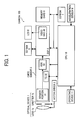
- FIG.1 is a functional block diagram showing an imaging apparatus such as a camera 100, according to an embodiment of the present invention.
- the camera 100 as the imaging apparatus according to the embodiment of the present invention includes an image pickup device 3 configured to image a subject image and output image signals in an array corresponding to the subject image, an evaluation-value generating device 4 configured to read the image signals in a direction (referred to as "reading direction” hereinafter) and generate evaluation values based on the read image signals, an orientation detecting device 9 configured to detect an orientation of the imaging apparatus, and a control device 10 configured to change the reading direction of the evaluation-value generating device in accordance with the orientation of the imaging apparatus.
- image pickup device 3 configured to image a subject image and output image signals in an array corresponding to the subject image
- an evaluation-value generating device 4 configured to read the image signals in a direction (referred to as "reading direction” hereinafter) and generate evaluation values based on the read image signals
- an orientation detecting device 9 configured to detect an orientation of the imaging apparatus
- the evaluation-value generating device 4 is, for example, a digital signal processor (DSP) 4 which performs image signal processing.
- the control device 10 is, for example, a CPU 10 which controls the entire operation of the camera 100.
- the image pickup device 3 may be configured to output the image signals in a changeable scanning direction and may be, for example, a CMOS sensor 3 having two-dimensionally arranged pixels.
- the orientation detecting device 9 may be an attitude detecting device configured to detect an attitude of the camera including a position and an orientation of the imaging apparatus.
- an acceleration sensor 9 configured to detect the acceleration of the imaging apparatus to determine the direction of the camera 100, that is, the orientation of the imaging apparatus is used.
- the evaluation-value generating device 4 may be configured to generate an AF evaluation value based on a frequency component of the image signal of the subject image.
- the camera 100 includes an optical system 1 having a lens 1a and a shutter 1b, a focus adjustment device such as a motor driver 2 configured to adjust a focal point of the optical system 1 of the camera 100 based on a command of the CPU 10, including, for example, the AF evaluation value, an SDRAM 5 configured to store RAW data or data obtained by processing signals, a memory card 6 configured to store a photographed subject image, an EEPROM 7 configured to hold various adjustment values used for generating an AF evaluation value, an LCD 8 configured to display a confirmation image for confirming a photographed image, replayed image or operation setting information of the camera 100, and an operating device 11 which is used for performing a photographing operation or a setting operation of the camera 100.
- a focus adjustment device such as a motor driver 2 configured to adjust a focal point of the optical system 1 of the camera 100 based on a command of the CPU 10,
- the CMOS sensor 3 includes a sensor portion 31 which outputs image signals based on a subject image photographed via the optical system 1, a timing generator (TG) 32 which controls a sampling timing of outputs of the sensor portion 31, and an AD convertor (ADC) 33 which converts the outputs of the sensor portion 31 into digital data.
- TG timing generator
- ADC AD convertor
- the digital data output from the CMOS sensor 3 are stored in the SDRAM 5 as RAW data arranged in an array corresponding to the array of the two-dimensionally arranged pixels of the CMOS sensor.
- image signals indicates the above-described "RAW data".
- the DSP 4 generates evaluation values for automatic exposure (AE), white balance correction, or the like, as well as generating the AF evaluation values based on the image signals output from the CMOS sensor.
- the CPU 10 controls operation of the motor driver 2 by use of the evaluation values.
- the DSP 4 reads out the RAW data from the SDRAM 5, generates a brightness signal and a color signal, performs a JPEG processing, and then stores the processed signals in the memory card 6.
- the data converted into RGB or YUV to be displayed from the RAW data are output from a Video DAC (digital-analog converter for video) 41 and then displayed on the LCD 8.
- Video DAC digital-analog converter for video
- the CPU 10 performs control of the AF, the AE, the white balance correction, or the like, based on the evaluation values generated by the DSP 4.
- the CPU 10 has a function of setting parameters for devices such as the CMOS sensor 3, the DSP 4, and the like, a function of performing processing in accordance with an input from the operating device 11 operated by a photographer, and the like.
- the CPU 10 controls the driving pulse of a focus motor via the motor driver 2 based on the AF evaluation value.
- the scanning direction of the CMOS sensor 3 and/or the reading direction of the DSP 4 may be changed by operating the operating device 11.
- the CPU 10 determines whether the camera is in a horizontal state or in a vertical state based on a direction of the camera 100, which is obtained by the acceleration sensor 9.
- the horizontal state is, as a normal state for photographing, for example, in a state where a longitudinal direction of the CMOS sensor 3 is substantially parallel to the horizontal direction
- the vertical state is, for example, a state where the longitudinal direction of the CMOS sensor 3 is substantially perpendicular to the horizontal direction.
- the CPU 10 may be configured to set the reading direction of the DSP 4 to the longitudinal direction of the CMOS sensor 3 when the acceleration sensor 9 detects a horizontal orientation of the camera 100, and to a short-side direction of the CMOS sensor when the acceleration sensor 9 detects a vertical orientation of the camera 100.
- the CPU 10 sets a read-out area of the image signals output from the CMOS sensor 3 and the reading direction of the DSP 4 or the scanning direction of the CMOS sensor 3.
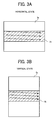
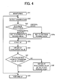
- FIG.2 the flow of the AF is shown by the steps S21 to S27.
- reference number 3a indicates an entire area of the image signals
- reference number 3b indicates a read-out area of the image signals for obtaining the AF evaluation values.
- the read-out area 3b is optionally set and it is preferable to set the read-out area 3b to an area including a center portion of the subject image, that is, a center of the entire area 3a.
- the reading direction is shown by arrows.
- the camera 100 images a subject image via the CMOS sensor 3 as the image pickup device to output image signals of the subject image and the image signals are input to the DSP 4 (S21).
- the acceleration sensor 9 detects the direction of the camera 100 (S22), and thereby, the CPU determines the orientation of the camera 100 (S23). If it is determined that the orientation of the camera 100 is a horizontal orientation, that is, the camera 100 is in the horizontal state, the CPU 10 sets the entire area 3a and the read-out area 3b as a horizontal reading mode, as shown in FIG.3A (S24a).
- the CPU sets the entire area 3a and the read-out area 3b as a vertical reading mode, as shown in FIG.3B (S24b).
- the image signals in the read-out area 3b set in the above steps are read out in the predetermined direction (S25), and the AF evaluation value is obtained (S26). That is, in a case where it is determined that the camera 100 is in the horizontal state in step S23, as shown in FIG.3A , in the horizontally long entire area 3a, a horizontally long read-out area 3b is set at a center portion in a vertical direction of the entire area 3a and a horizontal reading direction is set to generate the AF evaluation value. Thereby, any change of the AF evaluation value of the subject image having strong contrast in the horizontal direction can be appropriately detected so that high speed AF control can be achieved.
- the horizontally long read-out area 3b is set at a center portion in a vertical direction of the entire area 3a and a horizontal reading direction is set to generate the AF evaluation value.
- the CPU 10 performs a peak determination of the AF evaluation value based on the obtained AF evaluation values and controls a driving pulse of a driving motor of the optical system 1 via the motor driver 2 to move the optical system 1 to a focused focal position (S27).
- the orientation detection process in step S22 is performed when the subject image is taken in the image pickup device after turning on power of the camera 100
- the present invention is not limited thereto and the orientation detection may be repeatedly performed at intervals while the power of the camera 100 is on.
- the orientation detection may be performed when or after the shutter button which is included in the operating device 11 is pressed down.
- the CPU 10 is configured to change the reading direction of the image signals for obtaining the AF evaluation value in accordance with the direction of the camera 100 detected by the acceleration sensor 9, the present invention is not limited thereto and the CPU 10 may change the scanning direction in which the outputs of the image signals from the CMOS sensor 3 are scanned in accordance with the direction of the camera 100 detected by the acceleration sensor 9.
- the reading direction of the image signals for obtaining the AF value may be set to the same as the scanning direction of the CMOS sensor 3.
- the camera 100 images a subject image via the CMOS sensor 3 as the image pickup device to output image signals of the subject image, and the image signals are input to the DSP 4 (S41).
- the acceleration sensor 9 detects the direction of the camera 100 (S42), and thereby, the CPU determines the orientation of the camera 100 (S43). If it is determined that the orientation of the camera 100 is a horizontal orientation, that is, the camera 100 is in the horizontal state, the CPU 10 sets the entire area 3a and the read-out area 3b as a horizontal reading mode, as shown in FIG.3A (S44a).
- the CPU sets the entire area 3a and the read-out area 3b as a vertical reading mode, as shown in FIG.3B (S44b).
- the AF process is started in the reading direction which is set in the above steps, that is, the image signals in the read-out area 3b set in the above steps are read out in the set reading direction (S45), and the AF evaluation value is obtained (S46). Then, the CPU 10 compares the obtained AF evaluation value with a predetermined threshold value. If the AF evaluation value is the threshold value or more ("YES" in step S47), the CPU 10 performs the AF process based on the obtained AF evaluation value (S49).
- the CPU changes the reading direction of the image signals by the DSP 4 to another direction (for example, when the direction is set to the horizontal direction, it changes to the vertical reading direction), and the image signals are read-out by the DSP 4 to obtain the AF evaluation value (S48).
- the CPU 10 controls a driving pulse of the driving motor of the optical system 1 via the motor driver 2 to move the optical system 1 in accordance with the obtained AF evaluation value (S49).
- the CPU 10 may be configured to change the scanning direction of the outputs of the CMOS sensor 3 when the AF evaluation value is less than the threshold value.
- the camera 100 of the above embodiment of the present invention when photographing a subject image having horizontal stripes, that is, a subject image having contrast in the vertical direction, even in the case where the AF evaluation value obtained by reading-out the image signals in the vertical reading direction is small, and therefore the evaluation value sufficient to perform the AF control cannot be obtained, the setting of the reading direction or the scanning direction can be automatically changed to obtain the AF evaluation value so that the precise and high speed AF process can be achieved.
- the above change of the reading direction or the scanning direction may be operated by operating a not-illustrated switch of the operating device 11 by the photographer.
- the high-speed AF control can be achieved regardless of the orientation of the camera by using the appropriately determined reading direction of the image signals. That is, a precisely-focused image can be obtained regardless of the orientation of the camera.
- the present invention can be applied to a portable phone having a camera function, as well as to a digital camera.
- a portable phone having a camera function as well as to a digital camera.
- the present invention has been described in terms of exemplary embodiments, it is not limited thereto. It should be appreciated that variations may be made in the embodiments described by persons skilled in the art without departing from the scope of the present invention as defined by the following claims.
Landscapes
- Engineering & Computer Science (AREA)
- Multimedia (AREA)
- Signal Processing (AREA)
- Studio Devices (AREA)
- Automatic Focus Adjustment (AREA)
- Focusing (AREA)
- Transforming Light Signals Into Electric Signals (AREA)
- Testing, Inspecting, Measuring Of Stereoscopic Televisions And Televisions (AREA)
Applications Claiming Priority (1)
| Application Number | Priority Date | Filing Date | Title |
|---|---|---|---|
| JP2008030856A JP2009194469A (ja) | 2008-02-12 | 2008-02-12 | 撮像装置 |
Publications (3)
| Publication Number | Publication Date |
|---|---|
| EP2091233A2 true EP2091233A2 (de) | 2009-08-19 |
| EP2091233A3 EP2091233A3 (de) | 2010-05-26 |
| EP2091233B1 EP2091233B1 (de) | 2013-05-08 |
Family
ID=40637025
Family Applications (1)
| Application Number | Title | Priority Date | Filing Date |
|---|---|---|---|
| EP09250322.6A Ceased EP2091233B1 (de) | 2008-02-12 | 2009-02-10 | Abbildungsvorrichtung |
Country Status (2)
| Country | Link |
|---|---|
| EP (1) | EP2091233B1 (de) |
| JP (1) | JP2009194469A (de) |
Cited By (2)
| Publication number | Priority date | Publication date | Assignee | Title |
|---|---|---|---|---|
| EP2224725A3 (de) * | 2009-02-27 | 2011-03-02 | Casio Computer Co., Ltd. | Bildgebungsvorrichtung und Auto-Fokusverfahren |
| CN103959763A (zh) * | 2011-12-09 | 2014-07-30 | 惠普发展公司,有限责任合伙企业 | 基于定向来生成图像 |
Citations (1)
| Publication number | Priority date | Publication date | Assignee | Title |
|---|---|---|---|---|
| JP2004151608A (ja) | 2002-11-01 | 2004-05-27 | Fuji Photo Optical Co Ltd | オートフォーカスシステム |
Family Cites Families (8)
| Publication number | Priority date | Publication date | Assignee | Title |
|---|---|---|---|---|
| JP2940003B2 (ja) * | 1989-06-26 | 1999-08-25 | ソニー株式会社 | 映像信号記録装置 |
| US5239333A (en) * | 1990-01-05 | 1993-08-24 | Nikon Corporation | Camera exposure calculation device dependent on type of scene to be photographed |
| JPH04175739A (ja) * | 1990-11-09 | 1992-06-23 | Nikon Corp | 自動焦点カメラ |
| US6747690B2 (en) * | 2000-07-11 | 2004-06-08 | Phase One A/S | Digital camera with integrated accelerometers |
| EP1669788A4 (de) * | 2003-09-22 | 2011-10-19 | Sharp Kk | Positions-steuereinrichtung für eine fotografische linse |
| JP4290100B2 (ja) * | 2003-09-29 | 2009-07-01 | キヤノン株式会社 | 撮像装置及びその制御方法 |
| JP2007057763A (ja) * | 2005-08-24 | 2007-03-08 | Canon Inc | 焦点調節装置、及び焦点調節方法 |
| WO2007045714A1 (en) * | 2005-10-21 | 2007-04-26 | Nokia Corporation | A method and a device for reducing motion distortion in digital imaging |
-
2008
- 2008-02-12 JP JP2008030856A patent/JP2009194469A/ja active Pending
-
2009
- 2009-02-10 EP EP09250322.6A patent/EP2091233B1/de not_active Ceased
Patent Citations (1)
| Publication number | Priority date | Publication date | Assignee | Title |
|---|---|---|---|---|
| JP2004151608A (ja) | 2002-11-01 | 2004-05-27 | Fuji Photo Optical Co Ltd | オートフォーカスシステム |
Cited By (5)
| Publication number | Priority date | Publication date | Assignee | Title |
|---|---|---|---|---|
| EP2224725A3 (de) * | 2009-02-27 | 2011-03-02 | Casio Computer Co., Ltd. | Bildgebungsvorrichtung und Auto-Fokusverfahren |
| US8223255B2 (en) | 2009-02-27 | 2012-07-17 | Casio Computer Co., Ltd. | Imaging apparatus, auto-focusing method and recording medium |
| CN103959763A (zh) * | 2011-12-09 | 2014-07-30 | 惠普发展公司,有限责任合伙企业 | 基于定向来生成图像 |
| EP2789161A4 (de) * | 2011-12-09 | 2015-07-22 | Hewlett Packard Development Co | Erzeugung von bildern auf orientierungsbasis |
| US9210339B2 (en) | 2011-12-09 | 2015-12-08 | Hewlett-Packard Development Company, L.P. | Generation of images based on orientation |
Also Published As
| Publication number | Publication date |
|---|---|
| EP2091233A3 (de) | 2010-05-26 |
| EP2091233B1 (de) | 2013-05-08 |
| JP2009194469A (ja) | 2009-08-27 |
Similar Documents
| Publication | Publication Date | Title |
|---|---|---|
| US8300112B2 (en) | Image processing apparatus and control method therefor | |
| US7791668B2 (en) | Digital camera | |
| JP4761146B2 (ja) | 撮像装置及びそのプログラム | |
| JP4457358B2 (ja) | 顔検出枠の表示方法、文字情報の表示方法及び撮像装置 | |
| CN101621624B (zh) | 焦点调节设备及其控制方法 | |
| JP4518157B2 (ja) | 撮像装置及びそのプログラム | |
| US20100002127A1 (en) | Image pickup apparatus and auto-focus detection method | |
| US20140071318A1 (en) | Imaging apparatus | |
| JP5051812B2 (ja) | 撮像装置、その合焦方法および記録媒体 | |
| JP2006208558A (ja) | 撮像装置 | |
| JP5272551B2 (ja) | 撮像装置及び方法 | |
| JP2007108412A (ja) | オートフォーカス装置及びそのプログラム | |
| EP1335589A1 (de) | Bildaufnahmegerät | |
| KR101613529B1 (ko) | 카메라 모듈 | |
| JP2009157123A (ja) | 撮像装置 | |
| KR100850466B1 (ko) | 촬상 장치 및 그 오토 포커스 제어 방법 | |
| JP2008085737A (ja) | 電子カメラ | |
| JP5429588B2 (ja) | 撮像装置および撮像方法 | |
| JP6172973B2 (ja) | 画像処理装置 | |
| JP4853707B2 (ja) | 撮像装置及びそのプログラム | |
| EP2091233A2 (de) | Abbildungsvorrichtung | |
| JP2011107550A (ja) | 撮像装置 | |
| JP3628648B2 (ja) | 光学系制御装置 | |
| JP2007133301A (ja) | オートフォーカスカメラ | |
| JP5965653B2 (ja) | 追尾装置及び追尾方法 |
Legal Events
| Date | Code | Title | Description |
|---|---|---|---|
| PUAI | Public reference made under article 153(3) epc to a published international application that has entered the european phase |
Free format text: ORIGINAL CODE: 0009012 |
|
| AK | Designated contracting states |
Kind code of ref document: A2 Designated state(s): AT BE BG CH CY CZ DE DK EE ES FI FR GB GR HR HU IE IS IT LI LT LU LV MC MK MT NL NO PL PT RO SE SI SK TR |
|
| AX | Request for extension of the european patent |
Extension state: AL BA RS |
|
| PUAL | Search report despatched |
Free format text: ORIGINAL CODE: 0009013 |
|
| AK | Designated contracting states |
Kind code of ref document: A3 Designated state(s): AT BE BG CH CY CZ DE DK EE ES FI FR GB GR HR HU IE IS IT LI LT LU LV MC MK MT NL NO PL PT RO SE SI SK TR |
|
| AX | Request for extension of the european patent |
Extension state: AL BA RS |
|
| 17P | Request for examination filed |
Effective date: 20101025 |
|
| AKX | Designation fees paid |
Designated state(s): DE FR GB |
|
| 17Q | First examination report despatched |
Effective date: 20110321 |
|
| GRAP | Despatch of communication of intention to grant a patent |
Free format text: ORIGINAL CODE: EPIDOSNIGR1 |
|
| GRAS | Grant fee paid |
Free format text: ORIGINAL CODE: EPIDOSNIGR3 |
|
| GRAA | (expected) grant |
Free format text: ORIGINAL CODE: 0009210 |
|
| AK | Designated contracting states |
Kind code of ref document: B1 Designated state(s): DE FR GB |
|
| REG | Reference to a national code |
Ref country code: GB Ref legal event code: FG4D |
|
| REG | Reference to a national code |
Ref country code: DE Ref legal event code: R096 Ref document number: 602009015541 Country of ref document: DE Effective date: 20130704 |
|
| PLBE | No opposition filed within time limit |
Free format text: ORIGINAL CODE: 0009261 |
|
| STAA | Information on the status of an ep patent application or granted ep patent |
Free format text: STATUS: NO OPPOSITION FILED WITHIN TIME LIMIT |
|
| 26N | No opposition filed |
Effective date: 20140211 |
|
| REG | Reference to a national code |
Ref country code: DE Ref legal event code: R097 Ref document number: 602009015541 Country of ref document: DE Effective date: 20140211 |
|
| REG | Reference to a national code |
Ref country code: FR Ref legal event code: PLFP Year of fee payment: 8 |
|
| REG | Reference to a national code |
Ref country code: FR Ref legal event code: PLFP Year of fee payment: 9 |
|
| REG | Reference to a national code |
Ref country code: FR Ref legal event code: PLFP Year of fee payment: 10 |
|
| PGFP | Annual fee paid to national office [announced via postgrant information from national office to epo] |
Ref country code: GB Payment date: 20180216 Year of fee payment: 10 Ref country code: DE Payment date: 20180219 Year of fee payment: 10 |
|
| PGFP | Annual fee paid to national office [announced via postgrant information from national office to epo] |
Ref country code: FR Payment date: 20180223 Year of fee payment: 10 |
|
| REG | Reference to a national code |
Ref country code: DE Ref legal event code: R119 Ref document number: 602009015541 Country of ref document: DE |
|
| GBPC | Gb: european patent ceased through non-payment of renewal fee |
Effective date: 20190210 |
|
| PG25 | Lapsed in a contracting state [announced via postgrant information from national office to epo] |
Ref country code: DE Free format text: LAPSE BECAUSE OF NON-PAYMENT OF DUE FEES Effective date: 20190903 Ref country code: GB Free format text: LAPSE BECAUSE OF NON-PAYMENT OF DUE FEES Effective date: 20190210 |
|
| PG25 | Lapsed in a contracting state [announced via postgrant information from national office to epo] |
Ref country code: FR Free format text: LAPSE BECAUSE OF NON-PAYMENT OF DUE FEES Effective date: 20190228 |