EP2091300B1 - Dispositif de cuisson - Google Patents
Dispositif de cuisson Download PDFInfo
- Publication number
- EP2091300B1 EP2091300B1 EP09250313.5A EP09250313A EP2091300B1 EP 2091300 B1 EP2091300 B1 EP 2091300B1 EP 09250313 A EP09250313 A EP 09250313A EP 2091300 B1 EP2091300 B1 EP 2091300B1
- Authority
- EP
- European Patent Office
- Prior art keywords
- electromagnetic generating
- cooking device
- electromagnetic
- plate
- sections
- Prior art date
- Legal status (The legal status is an assumption and is not a legal conclusion. Google has not performed a legal analysis and makes no representation as to the accuracy of the status listed.)
- Active
Links
Images






Classifications
-
- H—ELECTRICITY
- H05—ELECTRIC TECHNIQUES NOT OTHERWISE PROVIDED FOR
- H05B—ELECTRIC HEATING; ELECTRIC LIGHT SOURCES NOT OTHERWISE PROVIDED FOR; CIRCUIT ARRANGEMENTS FOR ELECTRIC LIGHT SOURCES, IN GENERAL
- H05B6/00—Heating by electric, magnetic or electromagnetic fields
- H05B6/64—Heating using microwaves
- H05B6/72—Radiators or antennas
- H05B6/725—Rotatable antennas
-
- F—MECHANICAL ENGINEERING; LIGHTING; HEATING; WEAPONS; BLASTING
- F24—HEATING; RANGES; VENTILATING
- F24C—DOMESTIC STOVES OR RANGES ; DETAILS OF DOMESTIC STOVES OR RANGES, OF GENERAL APPLICATION
- F24C15/00—Details
- F24C15/006—Arrangements for circulation of cooling air
-
- H—ELECTRICITY
- H05—ELECTRIC TECHNIQUES NOT OTHERWISE PROVIDED FOR
- H05B—ELECTRIC HEATING; ELECTRIC LIGHT SOURCES NOT OTHERWISE PROVIDED FOR; CIRCUIT ARRANGEMENTS FOR ELECTRIC LIGHT SOURCES, IN GENERAL
- H05B6/00—Heating by electric, magnetic or electromagnetic fields
- H05B6/64—Heating using microwaves
- H05B6/642—Cooling of the microwave components and related air circulation systems
-
- H—ELECTRICITY
- H05—ELECTRIC TECHNIQUES NOT OTHERWISE PROVIDED FOR
- H05B—ELECTRIC HEATING; ELECTRIC LIGHT SOURCES NOT OTHERWISE PROVIDED FOR; CIRCUIT ARRANGEMENTS FOR ELECTRIC LIGHT SOURCES, IN GENERAL
- H05B2206/00—Aspects relating to heating by electric, magnetic, or electromagnetic fields covered by group H05B6/00
- H05B2206/04—Heating using microwaves
- H05B2206/044—Microwave heating devices provided with two or more magnetrons or microwave sources of other kind
Definitions
- the domestic-use cooking device provides one magnetron, and is configured to emit microwave generated by the magnetron to the heating chamber, with propagation of the microwave through one wave guide.
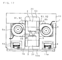
- the business-use cooking device provides: one pair of magnetrons that are laterally spaced apart each other and arranged in parallel on one side of an upper portion of a heating chamber; two wave guides that are arranged on upper sides of the respective magnetrons; two fans that are arranged on lower sides of the respective magnetrons; and two blowing paths that guide air, which is flown by the respective fans, around the respective magnetrons.
- the business-use cooking device is configured to emit microwave generated by the pair of magnetrons to the heating chamber, with propagation of the microwave through two wave guides (e.g. Japanese Patent Application Laid-Open No. 5-322187 ).
- the insulating plate is supported by insertion into a gap between the second partition plate and the air regulating plate. It is thus possible to insert the insulating plate for support into a gap between the second partition plate and the air regulating plate. Furthermore, it is possible to pull out the insulating plate from the gap between the second partition plate and the air regulating plate. Therefore, the cooking device has an advantage to improve maintenance actions, because of facilitating to mount/demount the insulating plate when mounting/demounting the electromagnetic generating unit for maintenance.
- the second partition plate is spaced apart vertically and laterally from an edge of the aperture area. It is thus possible to insert the insulating plate inside of the regulating plate through a gap between the second partition plate and the edge of the aperture area, even though lateral distance between the second partition plate and one air regulating plate is different from lateral distance between the second partition plate and another air regulating plate, by transforming the insulating plate which is arranged on a shorter-lateral distance side. Therefore, the cooking device has an advantage to enhance operability for mounting the insulating plate.
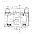
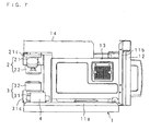
- the covering member 11d provides grille-shaped first and second exhaust ports 1g, 1h at front portions of the both lateral sides (cf. FIG. 5 ).
Landscapes
- Physics & Mathematics (AREA)
- Electromagnetism (AREA)
- Engineering & Computer Science (AREA)
- Chemical & Material Sciences (AREA)
- Combustion & Propulsion (AREA)
- Mechanical Engineering (AREA)
- General Engineering & Computer Science (AREA)
- Electric Ovens (AREA)
- Constitution Of High-Frequency Heating (AREA)
Claims (9)
- Dispositif de cuisson, comportant : une première unité de génération électromagnétique (2) et une deuxième unité de génération électromagnétique (3) permettant de générer les ondes électromagnétiques nécessaires à la cuisson ; une chambre de chauffage (1a) destinée à introduire les ondes électromagnétiques générées par la première (2) et la deuxième (3) unités de génération électromagnétique, pour chauffer un objet ; des ventilateurs (6, 6a) pour refroidir la première (2) et la deuxième (3) unités de génération électromagnétique, respectivement ; et un premier trajet de soufflage et un deuxième trajet de soufflage (8, 8a) pour souffler l'air respectif déplacé par les ventilateurs (6, 6a) autour de la première (2) et de la deuxième (3) unités de génération électromagnétique, respectivement, caractérisé en ce que :la première unité de génération électromagnétique (2) est disposée dans une position supérieure, et la deuxième unité de génération électromagnétique (3) est disposée dans une position inférieure, dans lequelchacune desdites première (2) et seconde (3) unités de génération électromagnétique comporte dans le sens vertical :une section de génération électromagnétique (21, 31) ; etune section de commande (22, 32) destinée à commander la section de génération électromagnétique (21, 31) ;les sections de commande (22, 32) sont opposées l'une à l'autre, dans une direction alternée, etles sections de génération électromagnétique (21, 31) et les sections de commande (22, 32) sont colinéaires dans la direction verticale.
- Dispositif de cuisson selon la revendication 1, comportant en outre :un conduit de ventilation (9) destiné à circonscrire, à la fois, les périphéries latérales de la première (2) et de la deuxième (3) unités de génération électromagnétique ; et une cloison de séparation (10) permettant de diviser verticalement un espace intérieur du conduit de ventilation (9) en une partie destinée à la section de commande (22, 32) et une partie destinée à la section de génération électromagnétique (21, 31) de chacune de la première (2) et de la deuxième (3) unités de génération d'ondes électromagnétiques.
- Dispositif de cuisson selon la revendication 2, dans lequel
la cloison de séparation (10) comporte :une première plaque de séparation (10a) se prolongeant dans une direction alternée, sur les deux faces latérales des sections de commande (22, 32) à la fois de la première et de la deuxième unités de génération électromagnétique ; etdes deuxièmes plaques de séparation (10b, 10c) se prolongeant latéralement à partir de la première plaque de séparation. - Dispositif de cuisson selon l'une quelconque des revendications 1 à 3, comportant en outre :des plaques d'isolation (92, 92) disposées sur une face latérale des sections de commande (22, 32) à la fois de la première et de la deuxième unités de génération électromagnétique, dans lequel les plaques d'isolation possèdent des orifices d'insertion (92a, 92b) ; etdes lignes d'alimentation, reliées aux sections de commande (22, 23) à la fois de la première et de la deuxième unités de génération électromagnétique, au travers des orifices d'insertion (92a, 92b).
- Dispositif de cuisson selon la revendication 4, dans lequel
la plaque d'isolation (92) constitue une partie du conduit de ventilation (9). - Dispositif de cuisson selon la revendication 5, dans lequel
chacune des sections de commande (22,32) comporte une borne d'alimentation (22a, 32a) positionnée en saillie latérale,
le conduit de ventilation (9) comporte :une plaque de régulation d'air (91), disposée sur les deux faces latérales des sections de génération électromagnétique (21, 31) à la fois de la première et de la deuxième unités de génération électromagnétique, dans lequel la plaque de régulation d'air (91) possède une surface d'ouverture disposée en correspondance avec une disposition des bornes d'alimentation (22a, 32a),la plaque d'isolation (92) est superposée à la plaque de régulation d'air (91), etl'orifice d'insertion (92a, 92b) est ouvert latéralement en fonction d'une position de la borne d'alimentation (22a, 32a). - Dispositif de cuisson selon la revendication 6, dans lequel
la ligne d'alimentation (20) comporte :un connecteur (20a) relié à la borne d'alimentation (22a, 32a) et disposé à l'intérieur de l'orifice d'insertion (92a, 92b), etla plaque d'isolation (92) est fixée au connecteur (20a) par un organe de blocage (30) qui bloque un espace entre l'orifice d'insertion (92a, 92b) et le connecteur (20a). - Dispositif de cuisson selon la revendication 6 ou 7, dans lequel :la plaque d'isolation (92) est soutenue par une insertion dans un espace ménagé entre la deuxième plaque de séparation (10b, 10c) et la plaque de régulation d'air (91).
- Dispositif de cuisson selon la revendication 8, dans lequel
la deuxième plaque de séparation (10b, 10c) est positionnée, verticalement et latéralement, à l'écart d'une bordure de la surface d'ouverture.
Applications Claiming Priority (1)
| Application Number | Priority Date | Filing Date | Title |
|---|---|---|---|
| JP2008035074A JP4637193B2 (ja) | 2008-02-15 | 2008-02-15 | 加熱調理器 |
Publications (2)
| Publication Number | Publication Date |
|---|---|
| EP2091300A1 EP2091300A1 (fr) | 2009-08-19 |
| EP2091300B1 true EP2091300B1 (fr) | 2013-04-24 |
Family
ID=40637171
Family Applications (1)
| Application Number | Title | Priority Date | Filing Date |
|---|---|---|---|
| EP09250313.5A Active EP2091300B1 (fr) | 2008-02-15 | 2009-02-06 | Dispositif de cuisson |
Country Status (4)
| Country | Link |
|---|---|
| US (1) | US20090206076A1 (fr) |
| EP (1) | EP2091300B1 (fr) |
| JP (1) | JP4637193B2 (fr) |
| CN (1) | CN101507579B (fr) |
Families Citing this family (3)
| Publication number | Priority date | Publication date | Assignee | Title |
|---|---|---|---|---|
| KR101741745B1 (ko) * | 2010-11-25 | 2017-05-31 | 동부대우전자 주식회사 | 전자레인지 |
| CN104869679B (zh) * | 2015-06-09 | 2017-08-04 | 内蒙古科技大学 | 一种实现变频微波加热的装置和方法 |
| CN107467094A (zh) * | 2017-09-22 | 2017-12-15 | 长齐胜餐饮管理(深圳)有限公司 | 微波热风联合烘烤设备及烧腊的烘制方法 |
Family Cites Families (15)
| Publication number | Priority date | Publication date | Assignee | Title |
|---|---|---|---|---|
| US3654417A (en) * | 1970-10-30 | 1972-04-04 | Litton Precision Prod Inc | Microwave oven including air flow system |
| FR2191254B1 (fr) * | 1972-06-30 | 1977-08-05 | Hitachi Ltd | |
| JPS58175725A (ja) * | 1982-04-07 | 1983-10-15 | Matsushita Electric Ind Co Ltd | 高周波加熱装置 |
| JPH0810630B2 (ja) * | 1988-02-29 | 1996-01-31 | 松下電器産業株式会社 | 高周波加熱装置 |
| JPH01225088A (ja) * | 1988-03-03 | 1989-09-07 | Matsushita Electric Ind Co Ltd | 高周波加熱装置 |
| JPH04121991A (ja) * | 1990-09-11 | 1992-04-22 | Matsushita Electric Ind Co Ltd | 高周波加熱装置 |
| FR2686684B1 (fr) * | 1992-01-23 | 1995-06-09 | Toshiba Ave Kk | Appareil de chauffage a hautes frequences. |
| JP2740411B2 (ja) | 1992-05-25 | 1998-04-15 | 三洋電機株式会社 | 電子レンジ |
| JPH08203664A (ja) * | 1995-01-26 | 1996-08-09 | Sanyo Electric Co Ltd | 電子レンジ |
| GB2344501A (en) * | 1999-07-02 | 2000-06-07 | Merrychef Ltd | Antenna disposition in microwave heating apparatus |
| JP2001108243A (ja) * | 1999-10-01 | 2001-04-20 | Sanyo Electric Co Ltd | 電子レンジ |
| CN1141514C (zh) * | 2000-11-20 | 2004-03-10 | 罗建华 | 一种微波装置 |
| JP3926118B2 (ja) * | 2001-07-24 | 2007-06-06 | 株式会社東芝 | 加熱調理器 |
| JP2003074872A (ja) * | 2001-09-05 | 2003-03-12 | Sanyo Electric Co Ltd | 高周波加熱調理器 |
| KR100436148B1 (ko) * | 2001-12-24 | 2004-06-14 | 삼성전자주식회사 | 전자렌지 |
-
2008
- 2008-02-15 JP JP2008035074A patent/JP4637193B2/ja not_active Expired - Fee Related
-
2009
- 2009-02-06 EP EP09250313.5A patent/EP2091300B1/fr active Active
- 2009-02-13 US US12/370,673 patent/US20090206076A1/en not_active Abandoned
- 2009-02-13 CN CN2009100072155A patent/CN101507579B/zh not_active Expired - Fee Related
Also Published As
| Publication number | Publication date |
|---|---|
| JP4637193B2 (ja) | 2011-02-23 |
| CN101507579A (zh) | 2009-08-19 |
| EP2091300A1 (fr) | 2009-08-19 |
| JP2009192179A (ja) | 2009-08-27 |
| CN101507579B (zh) | 2011-08-24 |
| US20090206076A1 (en) | 2009-08-20 |
Similar Documents
| Publication | Publication Date | Title |
|---|---|---|
| KR20080078760A (ko) | 유도 가열기 | |
| US8513579B2 (en) | Heater assembly for microwave oven and microwave oven having the same | |
| JP2002221324A (ja) | フード兼用電子レンジの電装部品の冷却装置 | |
| EP2091300B1 (fr) | Dispositif de cuisson | |
| US6852963B2 (en) | Wall-mounted type microwave oven | |
| US4549054A (en) | Microwave oven construction having separate component receiving chambers | |
| US6660984B1 (en) | Wall-mounted type microwave oven | |
| CN112971551A (zh) | 烹饪装置 | |
| KR20230103499A (ko) | 후드 겸용 전자 레인지 | |
| KR20220165594A (ko) | 전기 레인지 | |
| KR20180079870A (ko) | 조리기기 | |
| KR101207306B1 (ko) | 컨벡션히팅유닛 및 이를 갖는 가열조리기 | |
| US7692124B2 (en) | Air flow passage of microwave oven | |
| KR101652999B1 (ko) | 후드 겸용 전자레인지 | |
| KR19980074659A (ko) | 전자레인지 | |
| KR20040021150A (ko) | 전자레인지의 캐비티 일체형 히터어셈블리 | |
| KR100595261B1 (ko) | 컨벡션형 전자레인지 | |
| KR101012354B1 (ko) | 전자 레인지 | |
| KR102037380B1 (ko) | 조리 기기 | |
| CN121444590A (zh) | 电炉 | |
| KR100983267B1 (ko) | 토스터 겸용 전자 레인지 | |
| KR19990018403U (ko) | 전자렌지의 멀티형 도파관 | |
| KR20000004983U (ko) | 전자렌지의 후면커버 | |
| KR20000003595U (ko) | 전자레인지 | |
| KR20040061356A (ko) | 후드겸용 전자레인지 |
Legal Events
| Date | Code | Title | Description |
|---|---|---|---|
| PUAI | Public reference made under article 153(3) epc to a published international application that has entered the european phase |
Free format text: ORIGINAL CODE: 0009012 |
|
| AK | Designated contracting states |
Kind code of ref document: A1 Designated state(s): AT BE BG CH CY CZ DE DK EE ES FI FR GB GR HR HU IE IS IT LI LT LU LV MC MK MT NL NO PL PT RO SE SI SK TR |
|
| AX | Request for extension of the european patent |
Extension state: AL BA RS |
|
| 17P | Request for examination filed |
Effective date: 20100212 |
|
| AKX | Designation fees paid |
Designated state(s): DE FR GB |
|
| GRAP | Despatch of communication of intention to grant a patent |
Free format text: ORIGINAL CODE: EPIDOSNIGR1 |
|
| GRAS | Grant fee paid |
Free format text: ORIGINAL CODE: EPIDOSNIGR3 |
|
| GRAA | (expected) grant |
Free format text: ORIGINAL CODE: 0009210 |
|
| AK | Designated contracting states |
Kind code of ref document: B1 Designated state(s): DE FR GB |
|
| REG | Reference to a national code |
Ref country code: GB Ref legal event code: FG4D |
|
| REG | Reference to a national code |
Ref country code: DE Ref legal event code: R096 Ref document number: 602009015175 Country of ref document: DE Effective date: 20130620 |
|
| PLBE | No opposition filed within time limit |
Free format text: ORIGINAL CODE: 0009261 |
|
| STAA | Information on the status of an ep patent application or granted ep patent |
Free format text: STATUS: NO OPPOSITION FILED WITHIN TIME LIMIT |
|
| 26N | No opposition filed |
Effective date: 20140127 |
|
| REG | Reference to a national code |
Ref country code: DE Ref legal event code: R097 Ref document number: 602009015175 Country of ref document: DE Effective date: 20140127 |
|
| REG | Reference to a national code |
Ref country code: DE Ref legal event code: R084 Ref document number: 602009015175 Country of ref document: DE |
|
| REG | Reference to a national code |
Ref country code: GB Ref legal event code: 746 Effective date: 20140918 |
|
| REG | Reference to a national code |
Ref country code: DE Ref legal event code: R084 Ref document number: 602009015175 Country of ref document: DE Effective date: 20141002 |
|
| REG | Reference to a national code |
Ref country code: FR Ref legal event code: PLFP Year of fee payment: 8 |
|
| REG | Reference to a national code |
Ref country code: FR Ref legal event code: PLFP Year of fee payment: 9 |
|
| REG | Reference to a national code |
Ref country code: FR Ref legal event code: PLFP Year of fee payment: 10 |
|
| PGFP | Annual fee paid to national office [announced via postgrant information from national office to epo] |
Ref country code: FR Payment date: 20210225 Year of fee payment: 13 |
|
| PGFP | Annual fee paid to national office [announced via postgrant information from national office to epo] |
Ref country code: DE Payment date: 20210217 Year of fee payment: 13 |
|
| REG | Reference to a national code |
Ref country code: DE Ref legal event code: R119 Ref document number: 602009015175 Country of ref document: DE |
|
| PG25 | Lapsed in a contracting state [announced via postgrant information from national office to epo] |
Ref country code: FR Free format text: LAPSE BECAUSE OF NON-PAYMENT OF DUE FEES Effective date: 20220228 |
|
| PG25 | Lapsed in a contracting state [announced via postgrant information from national office to epo] |
Ref country code: DE Free format text: LAPSE BECAUSE OF NON-PAYMENT OF DUE FEES Effective date: 20220901 |
|
| PGFP | Annual fee paid to national office [announced via postgrant information from national office to epo] |
Ref country code: GB Payment date: 20260220 Year of fee payment: 18 |