EP2091312B2 - Boîtier électronique pouvant être joint doté de baguettes à crayon ou manchon - Google Patents
Boîtier électronique pouvant être joint doté de baguettes à crayon ou manchon Download PDFInfo
- Publication number
- EP2091312B2 EP2091312B2 EP09150924.0A EP09150924A EP2091312B2 EP 2091312 B2 EP2091312 B2 EP 2091312B2 EP 09150924 A EP09150924 A EP 09150924A EP 2091312 B2 EP2091312 B2 EP 2091312B2
- Authority
- EP
- European Patent Office
- Prior art keywords
- unlocking
- pin
- housing
- pin strip
- strip
- Prior art date
- Legal status (The legal status is an assumption and is not a legal conclusion. Google has not performed a legal analysis and makes no representation as to the accuracy of the status listed.)
- Active
Links
Images


Classifications
-
- H—ELECTRICITY
- H01—ELECTRIC ELEMENTS
- H01R—ELECTRICALLY-CONDUCTIVE CONNECTIONS; STRUCTURAL ASSOCIATIONS OF A PLURALITY OF MUTUALLY-INSULATED ELECTRICAL CONNECTING ELEMENTS; COUPLING DEVICES; CURRENT COLLECTORS
- H01R13/00—Details of coupling devices of the kinds covered by groups H01R12/70 or H01R24/00 - H01R33/00
- H01R13/62—Means for facilitating engagement or disengagement of coupling parts or for holding them in engagement
- H01R13/629—Additional means for facilitating engagement or disengagement of coupling parts, e.g. aligning or guiding means, levers, gas pressure electrical locking indicators, manufacturing tolerances
- H01R13/62933—Comprising exclusively pivoting lever
-
- H—ELECTRICITY
- H01—ELECTRIC ELEMENTS
- H01R—ELECTRICALLY-CONDUCTIVE CONNECTIONS; STRUCTURAL ASSOCIATIONS OF A PLURALITY OF MUTUALLY-INSULATED ELECTRICAL CONNECTING ELEMENTS; COUPLING DEVICES; CURRENT COLLECTORS
- H01R9/00—Structural associations of a plurality of mutually-insulated electrical connecting elements, e.g. terminal strips or terminal blocks; Terminals or binding posts mounted upon a base or in a case; Bases therefor
- H01R9/22—Bases, e.g. strip, block, panel
- H01R9/24—Terminal blocks
- H01R9/26—Clip-on terminal blocks for side-by-side rail- or strip-mounting
- H01R9/2625—Clip-on terminal blocks for side-by-side rail- or strip-mounting with built-in electrical component
-
- H—ELECTRICITY
- H05—ELECTRIC TECHNIQUES NOT OTHERWISE PROVIDED FOR
- H05K—PRINTED CIRCUITS; CASINGS OR CONSTRUCTIONAL DETAILS OF ELECTRIC APPARATUS; MANUFACTURE OF ASSEMBLAGES OF ELECTRICAL COMPONENTS
- H05K7/00—Constructional details common to different types of electric apparatus
- H05K7/14—Mounting supporting structure in casing or on frame or rack
- H05K7/1462—Mounting supporting structure in casing or on frame or rack for programmable logic controllers [PLC] for automation or industrial process control
- H05K7/1468—Mechanical features of input/output (I/O) modules
- H05K7/1469—Terminal blocks for connecting sensors
Definitions
- the invention relates to a stackable housing arrangement according to claim 1 with a housing, in particular electronics housing.
- Such a housing is of the generic type EP 1 083 637 A known.
- the DE 10 2004 002 737 A1 relates to a release mechanism for a latched plug or socket part of an electrical connector, in particular a plug module from the base terminal of a field bus for the parallel wiring of actuators and sensors.
- at least one pivotally mounted lever is arranged transversely to the direction of pull of the plug module on at least one longitudinal recess of the plug module and is designed as an eccentric at one end.
- the electronics housing is designed as a module that can be snapped onto a mounting rail, the installation conditions are generally quite narrow.
- the object of the invention is to solve this problem with simple constructive means.
- the unlocking device supports the detachment of the plug connection between the plug and the socket strip in a simple manner. Unlocking is thus to be understood as at least supporting the separation of the two elements of the pin strip and socket strip from one another. It advantageously does not enlarge the overall width of the actual housing, in particular the electronics housing, in the direction of attachment, so that it is excellently suited for use on terminal block-type housings.
- Only one or more pin headers and / or socket headers can be arranged on the electronics housing.
- One of the unlocking devices is preferably assigned to each such terminal strip.
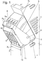
- Figure 1 shows a portion of an electronics housing 1, which preferably has a terminal-like structure in a manner not shown and is designed for snapping onto a mounting rail, not shown here.
- the direction of installation on the mounting rail is in Figure 1 indicated by the direction of arrow X.
- the housing has an X1 width.
- the installation space in the direction X is relatively short, for example the electronics housing 1 can have a width X1 of only a few millimeters.
- At least one pin strip 2 is arranged or formed on the electronics housing 1, which can be firmly connected to the electronics housing 1 or even in one piece with the housing, which surrounds the contact pins (not shown here).
- a socket strip 3 is plugged onto the pin strip 2, which can be placed essentially vertically or slightly obliquely to the vertical (relative to the mounting rail) from above onto the pin strip 2 and can preferably be latched to it and detachable from it in the opposite direction.
- an unlocking device 4 is arranged on the socket strip 3, which is designed here as a pivotable unlocking bracket 5, which is articulated on opposite sides of the socket strip 2 with the socket strip 2 on axes of rotation 6.
- the unlocking bracket 5 essentially has a U-shape with a base leg 7a and two side legs 7b, 7c.
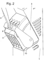
- the unlocking bracket 5 engages around the socket strip 3 from above, the base leg 7a being arranged essentially above (relative to the support rail) of the socket strip 3 and here being pivotable in the direction of the arrow S in the direction of the support rail.
- the base leg 7a preferably has an actuating contour 8 for attaching a tool, which here is designed as a slot for attaching a screwdriver 9. A manual actuation on an attachment of the bracket or the like would also be conceivable (not shown here).
- the two longitudinal legs 7b, 7c aligned parallel to one another are in turn preferably parallel to the main outer surfaces 8a, 8b of the electronics housing, which are located in the row direction (or against the row direction) X.
- the socket strip with the unlocking device and the unlocking bracket 5 advantageously has a width X2 in the direction of attachment which is at least not greater or even smaller than the grid width X1 of the electronics housing in the direction of attachment. In this way, the unlocking device does not increase the overall width of the electronics housing in the direction X.
- unlocking bracket 5 is aligned with the main outer walls of the electronics housing 1 in the direction of the row.
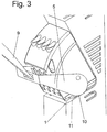
- this unlocking contour 10 which has an eccentrically extending contour relative to the pivot axes 6, this unlocking contour 10 being located on a support surface 11 of the electronics housing (or alternatively the pin strip, not shown here ) supports. It is particularly preferred if the unlocking contour 10 is supported on the electronics housing 1.
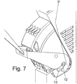
- the unlocking bracket 5 is now pivoted downward about the pivot axes 6 using a screwdriver 12, so that the unlocking contour 10, the distance from the pivot axis 6 of which increases with the pivoting of the unlocking bracket into the release position (here downward), the socket strip 3 from the pin header 2, since the unlocking contour 10 is supported on the support surface 11 in the manner of an abutment.
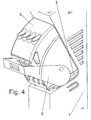
- a slot 12 on the unlocking bracket 5 which slot has an arc shape and is designed to interact with a pin 13 on the pin header 1 or on the electronics housing 1.
- the slot is open at one end and extends essentially perpendicular to the plug-in direction in which the socket strip is attached and detached.
- the unlocking bracket 5 is moved into its lower position in this illustration - the unlocking position - so that the socket strip 3 can be plugged onto the pin strip 2 and locked there.
Landscapes
- Engineering & Computer Science (AREA)
- Automation & Control Theory (AREA)
- Microelectronics & Electronic Packaging (AREA)
- Details Of Connecting Devices For Male And Female Coupling (AREA)
- Connector Housings Or Holding Contact Members (AREA)
- Casings For Electric Apparatus (AREA)
Claims (4)
- Disposition de boîtier pouvant être alignée, en particulier disposition de boîtier électronique, avec un boîtier, en particulier un boîtier électronique (1), dans laquelle le boîtier est doté d'au moins une ou plusieurs réglettes de broches et/ou réglettes de douilles, dans laquelle le boîtier présente dans le sens d'alignement une largeur de construction (X1), et avec une réglette de douilles (3) ou réglette de broches (2) correspondante de la disposition de boîtier emboîtable respectivement sur l'au moins une réglette de broches (2) ou réglette de douilles (3), dans laquelle un dispositif de déverrouillage (4) disposé sur une réglette de douilles ou réglette de broches (2, 3) emboîtable correspondante pour déverrouiller la réglette de douilles (3) de la réglette de broches (2) est prévu, la largeur de construction totale (X2) de la réglette de broches (2) correspondante ou de la réglette de douilles (3) correspondante avec le dispositif de déverrouillage (4) n'étant pas plus grande que la largeur de construction (X1) du boîtier, en particulier du boîtier électronique (1), dans le sens d'alignement, le dispositif de déverrouillage (4) étant construit comme un étrier de déverrouillage (5) pivotant qui est articulé à la réglette de douilles (2) ou à la réglette de broches (3) sur des axes de pivotement (6) sur des côtés opposés de celle-ci, dans laquelle l'étrier de déverrouillage (5) est doté d'un contour de déverrouillage (10) excentré par rapport aux axes de pivotement (6), qui s'appuie comme un contre-appui sur une surface d'appui (11) du boîtier ou de la réglette de broches lors du déverrouillage, dans laquelle l'étrier de déverrouillage (5) est aligné avec le boîtier électronique (1) dans le sens d'alignement et dans laquelle l'étrier de déverrouillage (5) est en forme de U avec un bras de base (7a) et deux bras latéraux (7b, 7c).
- Boîtier électronique selon la revendication 1, dans lequel l'étrier de déverrouillage (5) entoure la réglette de douilles (3) et le bras de base (7a) présente un contour d'actionnement (8).
- Boîtier électronique selon l'une des revendications précédentes, dans lequel le dispositif de déverrouillage (4) est combiné à un dispositif de verrouillage en formant une unité de construction.
- Boîtier électronique selon l'une des revendications précédentes, dans lequel l'étrier de déverrouillage (5) présente au moins une fente (12) conçue pour coopérer en vue du verrouillage avec un tenon (13) sur la réglette de broches (1) ou sur le boîtier électronique.
Applications Claiming Priority (1)
| Application Number | Priority Date | Filing Date | Title |
|---|---|---|---|
| DE202008002111U DE202008002111U1 (de) | 2008-02-14 | 2008-02-14 | Anreihbares Elektronikgehäuse mit Stift- oder Buchsenleisten |
Publications (4)
| Publication Number | Publication Date |
|---|---|
| EP2091312A2 EP2091312A2 (fr) | 2009-08-19 |
| EP2091312A3 EP2091312A3 (fr) | 2010-07-21 |
| EP2091312B1 EP2091312B1 (fr) | 2017-03-22 |
| EP2091312B2 true EP2091312B2 (fr) | 2020-06-10 |
Family
ID=40637015
Family Applications (1)
| Application Number | Title | Priority Date | Filing Date |
|---|---|---|---|
| EP09150924.0A Active EP2091312B2 (fr) | 2008-02-14 | 2009-01-20 | Boîtier électronique pouvant être joint doté de baguettes à crayon ou manchon |
Country Status (7)
| Country | Link |
|---|---|
| US (1) | US7736161B2 (fr) |
| EP (1) | EP2091312B2 (fr) |
| JP (2) | JP2009193959A (fr) |
| CN (1) | CN101521336A (fr) |
| DE (1) | DE202008002111U1 (fr) |
| DK (1) | DK2091312T4 (fr) |
| ES (1) | ES2628510T5 (fr) |
Families Citing this family (11)
| Publication number | Priority date | Publication date | Assignee | Title |
|---|---|---|---|---|
| EP2639895A1 (fr) * | 2012-03-16 | 2013-09-18 | EATON Industries Manufacturing GmbH | Prise électrique à bouchon de fermeture |
| DE202012101639U1 (de) * | 2012-05-03 | 2013-08-06 | Weidmüller Interface GmbH & Co. KG | Durchführungsgehäuse |
| DE102012105509B4 (de) * | 2012-06-25 | 2018-04-05 | Wago Verwaltungsgesellschaft Mbh | Elektronikgerätegehäuse |
| DE202012104581U1 (de) * | 2012-11-26 | 2014-02-27 | Weidmüller Interface GmbH & Co. KG | Anordnung aus zwei miteinander verriegelbaren, insbesondere elektrischen, Baugruppen |
| WO2014111323A1 (fr) * | 2013-01-15 | 2014-07-24 | Weidmüller Interface GmbH & Co. KG | Ensemble doté d'un module et d'un dispositif électronique |
| US20150031232A1 (en) * | 2013-07-24 | 2015-01-29 | International Business Machines Corporation | Electronic component latch |
| DE102014115252A1 (de) * | 2014-10-20 | 2016-04-21 | Phoenix Contact Gmbh & Co. Kg | Elektrisches Steckverbinderpaar |
| JP2018018584A (ja) * | 2016-07-25 | 2018-02-01 | 住友電装株式会社 | コネクタ |
| JP2018018583A (ja) * | 2016-07-25 | 2018-02-01 | 住友電装株式会社 | コネクタ |
| JP6268620B1 (ja) * | 2016-09-16 | 2018-01-31 | 住友電装株式会社 | レバー式コネクタ |
| JP7701918B2 (ja) * | 2019-11-15 | 2025-07-02 | リナック エー/エス | 制御ユニット |
Citations (4)
| Publication number | Priority date | Publication date | Assignee | Title |
|---|---|---|---|---|
| DE19737479A1 (de) † | 1997-08-28 | 1999-03-04 | Michael Dipl Ing Katzenberger | Werkzeug zum Herausziehen eines mehrpoligen elektronischen Bauelements (IC) aus einer Steckfassung |
| US6056582A (en) † | 1997-07-01 | 2000-05-02 | Yazaki Corporation | Lever fitting connector |
| DE102004002737A1 (de) † | 2004-01-20 | 2005-08-11 | Wago Verwaltungsgesellschaft Mbh | Lösemechanismus |
| EP1592092A1 (fr) † | 2004-04-28 | 2005-11-02 | Tyco Electronics AMP K.K. | Connecteur à levier |
Family Cites Families (9)
| Publication number | Priority date | Publication date | Assignee | Title |
|---|---|---|---|---|
| JPH07114951A (ja) * | 1993-10-18 | 1995-05-02 | Amp Japan Ltd | レバー式コネクタ |
| ES2183152T3 (es) * | 1996-12-02 | 2003-03-16 | Kao Corp | Compuesto tensoactivo. |
| JP2001076811A (ja) * | 1999-09-09 | 2001-03-23 | Sumitomo Wiring Syst Ltd | レバー式コネクタ |
| US20010034165A1 (en) * | 2000-03-10 | 2001-10-25 | Landis John M. | Terminal block connector |
| JP3603760B2 (ja) * | 2000-08-11 | 2004-12-22 | 住友電装株式会社 | レバー式コネクタ |
| JP3964146B2 (ja) * | 2001-03-22 | 2007-08-22 | 矢崎総業株式会社 | レバー嵌合式コネクタ |
| JP3952877B2 (ja) * | 2002-06-24 | 2007-08-01 | 松下電工株式会社 | リレー端子台 |
| DE10236397A1 (de) * | 2002-08-08 | 2004-02-26 | Wieland Electric Gmbh | Elektrisches Anschlusselement und Vorrichtung, insbesondere Schaltgerät mit einem solchen Anschlusselement |
| DE102005027824B4 (de) * | 2005-06-15 | 2013-09-12 | Eaton Industries Gmbh | Elektrische Schaltvorrichtung mit Steckvorrichtung |
-
2008
- 2008-02-14 DE DE202008002111U patent/DE202008002111U1/de not_active Expired - Lifetime
-
2009
- 2009-01-20 ES ES09150924T patent/ES2628510T5/es active Active
- 2009-01-20 DK DK09150924.0T patent/DK2091312T4/da active
- 2009-01-20 EP EP09150924.0A patent/EP2091312B2/fr active Active
- 2009-01-27 JP JP2009015277A patent/JP2009193959A/ja active Pending
- 2009-02-09 US US12/322,889 patent/US7736161B2/en active Active
- 2009-02-13 CN CN200910007449A patent/CN101521336A/zh active Pending
-
2013
- 2013-12-06 JP JP2013252964A patent/JP2014089967A/ja active Pending
Patent Citations (4)
| Publication number | Priority date | Publication date | Assignee | Title |
|---|---|---|---|---|
| US6056582A (en) † | 1997-07-01 | 2000-05-02 | Yazaki Corporation | Lever fitting connector |
| DE19737479A1 (de) † | 1997-08-28 | 1999-03-04 | Michael Dipl Ing Katzenberger | Werkzeug zum Herausziehen eines mehrpoligen elektronischen Bauelements (IC) aus einer Steckfassung |
| DE102004002737A1 (de) † | 2004-01-20 | 2005-08-11 | Wago Verwaltungsgesellschaft Mbh | Lösemechanismus |
| EP1592092A1 (fr) † | 2004-04-28 | 2005-11-02 | Tyco Electronics AMP K.K. | Connecteur à levier |
Also Published As
| Publication number | Publication date |
|---|---|
| EP2091312A2 (fr) | 2009-08-19 |
| ES2628510T3 (es) | 2017-08-03 |
| US7736161B2 (en) | 2010-06-15 |
| DK2091312T4 (da) | 2020-08-31 |
| EP2091312A3 (fr) | 2010-07-21 |
| JP2009193959A (ja) | 2009-08-27 |
| JP2014089967A (ja) | 2014-05-15 |
| EP2091312B1 (fr) | 2017-03-22 |
| US20090209122A1 (en) | 2009-08-20 |
| DK2091312T3 (en) | 2017-07-10 |
| DE202008002111U1 (de) | 2009-06-25 |
| CN101521336A (zh) | 2009-09-02 |
| ES2628510T5 (es) | 2021-03-04 |
Similar Documents
| Publication | Publication Date | Title |
|---|---|---|
| EP2091312B2 (fr) | Boîtier électronique pouvant être joint doté de baguettes à crayon ou manchon | |
| EP2339701B1 (fr) | Connecteur à fiche de plaquettes doté d'un dispositif de verrouillage | |
| EP2091108B2 (fr) | Connecteur à fiche doté d'un dispositif de codage | |
| DE202004018757U1 (de) | Vorrichtung zur elektrischen Überbrückung zweier Stromschienen | |
| DE102017117509B4 (de) | Elektrisches Gerät | |
| DE102012017429B4 (de) | Prüfklemmenblock und Baugruppe aus einer Befestigungsklemme und einem Befestigungsteil | |
| EP2606534A1 (fr) | Arrêt de rail support et de module | |
| EP3021421B1 (fr) | Dispositif de raccordement pour cable multiconducteur | |
| WO2013050239A1 (fr) | Dispositif de connexion servant à connecter un conducteur | |
| DE102007041406A1 (de) | Verriegelungseinrichtung für ein Gehäuse zur Aufnahme eines Einsteckmoduls | |
| WO2014023532A1 (fr) | Module de connexion | |
| DE10047676C1 (de) | Gehäuse für ein elektronisches Gerät | |
| EP1742315B1 (fr) | Boîtier modulaire pour le montage sur un rail de support | |
| DE102006054647B4 (de) | Elektrische Steckverbinderkupplung | |
| EP0086954B1 (fr) | Outil d'extraction d'un tiroir électronique de son support | |
| EP2425497B1 (fr) | Dispositif de fixation pour fixer une fiche de connexion à un boîtier de base | |
| EP1520330B1 (fr) | Support pour boitier de modules | |
| EP2432089B1 (fr) | Combinaison d'appareils pour la protection contre les surtensions | |
| EP1715547B1 (fr) | Système modulaire avec pont connecteur pour une ligne de bus interne | |
| EP3210261B1 (fr) | Module électronique | |
| EP2264470B1 (fr) | Système de raccordement pour compteurs d'électricité | |
| DE102005016760B4 (de) | Anordnung elektrischer bzw. elektronischer Geräte | |
| DE102004007740B4 (de) | Modulplatine und Trennbügel | |
| EP3627639B1 (fr) | Élément coulissant pour un mécanisme de suspension et d'encliquetage | |
| DE102006027014B4 (de) | Steckerwanne |
Legal Events
| Date | Code | Title | Description |
|---|---|---|---|
| PUAI | Public reference made under article 153(3) epc to a published international application that has entered the european phase |
Free format text: ORIGINAL CODE: 0009012 |
|
| AK | Designated contracting states |
Kind code of ref document: A2 Designated state(s): AT BE BG CH CY CZ DE DK EE ES FI FR GB GR HR HU IE IS IT LI LT LU LV MC MK MT NL NO PL PT RO SE SI SK TR |
|
| AX | Request for extension of the european patent |
Extension state: AL BA RS |
|
| PUAL | Search report despatched |
Free format text: ORIGINAL CODE: 0009013 |
|
| AK | Designated contracting states |
Kind code of ref document: A3 Designated state(s): AT BE BG CH CY CZ DE DK EE ES FI FR GB GR HR HU IE IS IT LI LT LU LV MC MK MT NL NO PL PT RO SE SI SK TR |
|
| AX | Request for extension of the european patent |
Extension state: AL BA RS |
|
| RIC1 | Information provided on ipc code assigned before grant |
Ipc: H05K 7/14 20060101ALI20100615BHEP Ipc: H05K 5/00 20060101AFI20090525BHEP Ipc: H01R 13/514 20060101ALI20100615BHEP Ipc: H01R 9/26 20060101ALI20100615BHEP Ipc: H01R 13/629 20060101ALI20100615BHEP |
|
| 17P | Request for examination filed |
Effective date: 20101122 |
|
| AKX | Designation fees paid |
Designated state(s): AT BE BG CH CY CZ DE DK EE ES FI FR GB GR HR HU IE IS IT LI LT LU LV MC MK MT NL NO PL PT RO SE SI SK TR |
|
| 17Q | First examination report despatched |
Effective date: 20130729 |
|
| GRAP | Despatch of communication of intention to grant a patent |
Free format text: ORIGINAL CODE: EPIDOSNIGR1 |
|
| INTG | Intention to grant announced |
Effective date: 20160928 |
|
| GRAJ | Information related to disapproval of communication of intention to grant by the applicant or resumption of examination proceedings by the epo deleted |
Free format text: ORIGINAL CODE: EPIDOSDIGR1 |
|
| GRAS | Grant fee paid |
Free format text: ORIGINAL CODE: EPIDOSNIGR3 |
|
| GRAP | Despatch of communication of intention to grant a patent |
Free format text: ORIGINAL CODE: EPIDOSNIGR1 |
|
| GRAA | (expected) grant |
Free format text: ORIGINAL CODE: 0009210 |
|
| INTC | Intention to grant announced (deleted) | ||
| INTG | Intention to grant announced |
Effective date: 20170206 |
|
| AK | Designated contracting states |
Kind code of ref document: B1 Designated state(s): AT BE BG CH CY CZ DE DK EE ES FI FR GB GR HR HU IE IS IT LI LT LU LV MC MK MT NL NO PL PT RO SE SI SK TR |
|
| REG | Reference to a national code |
Ref country code: GB Ref legal event code: FG4D Free format text: NOT ENGLISH |
|
| REG | Reference to a national code |
Ref country code: CH Ref legal event code: EP |
|
| REG | Reference to a national code |
Ref country code: AT Ref legal event code: REF Ref document number: 878885 Country of ref document: AT Kind code of ref document: T Effective date: 20170415 |
|
| REG | Reference to a national code |
Ref country code: IE Ref legal event code: FG4D Free format text: LANGUAGE OF EP DOCUMENT: GERMAN |
|
| REG | Reference to a national code |
Ref country code: DE Ref legal event code: R096 Ref document number: 502009013779 Country of ref document: DE |
|
| REG | Reference to a national code |
Ref country code: DK Ref legal event code: T3 Effective date: 20170704 |
|
| REG | Reference to a national code |
Ref country code: NL Ref legal event code: MP Effective date: 20170322 |
|
| PG25 | Lapsed in a contracting state [announced via postgrant information from national office to epo] |
Ref country code: GR Free format text: LAPSE BECAUSE OF FAILURE TO SUBMIT A TRANSLATION OF THE DESCRIPTION OR TO PAY THE FEE WITHIN THE PRESCRIBED TIME-LIMIT Effective date: 20170623 Ref country code: LT Free format text: LAPSE BECAUSE OF FAILURE TO SUBMIT A TRANSLATION OF THE DESCRIPTION OR TO PAY THE FEE WITHIN THE PRESCRIBED TIME-LIMIT Effective date: 20170322 Ref country code: FI Free format text: LAPSE BECAUSE OF FAILURE TO SUBMIT A TRANSLATION OF THE DESCRIPTION OR TO PAY THE FEE WITHIN THE PRESCRIBED TIME-LIMIT Effective date: 20170322 Ref country code: HR Free format text: LAPSE BECAUSE OF FAILURE TO SUBMIT A TRANSLATION OF THE DESCRIPTION OR TO PAY THE FEE WITHIN THE PRESCRIBED TIME-LIMIT Effective date: 20170322 Ref country code: NO Free format text: LAPSE BECAUSE OF FAILURE TO SUBMIT A TRANSLATION OF THE DESCRIPTION OR TO PAY THE FEE WITHIN THE PRESCRIBED TIME-LIMIT Effective date: 20170622 |
|
| REG | Reference to a national code |
Ref country code: ES Ref legal event code: FG2A Ref document number: 2628510 Country of ref document: ES Kind code of ref document: T3 Effective date: 20170803 |
|
| REG | Reference to a national code |
Ref country code: LT Ref legal event code: MG4D |
|
| PG25 | Lapsed in a contracting state [announced via postgrant information from national office to epo] |
Ref country code: SE Free format text: LAPSE BECAUSE OF FAILURE TO SUBMIT A TRANSLATION OF THE DESCRIPTION OR TO PAY THE FEE WITHIN THE PRESCRIBED TIME-LIMIT Effective date: 20170322 Ref country code: LV Free format text: LAPSE BECAUSE OF FAILURE TO SUBMIT A TRANSLATION OF THE DESCRIPTION OR TO PAY THE FEE WITHIN THE PRESCRIBED TIME-LIMIT Effective date: 20170322 Ref country code: BG Free format text: LAPSE BECAUSE OF FAILURE TO SUBMIT A TRANSLATION OF THE DESCRIPTION OR TO PAY THE FEE WITHIN THE PRESCRIBED TIME-LIMIT Effective date: 20170622 |
|
| PG25 | Lapsed in a contracting state [announced via postgrant information from national office to epo] |
Ref country code: NL Free format text: LAPSE BECAUSE OF FAILURE TO SUBMIT A TRANSLATION OF THE DESCRIPTION OR TO PAY THE FEE WITHIN THE PRESCRIBED TIME-LIMIT Effective date: 20170322 |
|
| PG25 | Lapsed in a contracting state [announced via postgrant information from national office to epo] |
Ref country code: CZ Free format text: LAPSE BECAUSE OF FAILURE TO SUBMIT A TRANSLATION OF THE DESCRIPTION OR TO PAY THE FEE WITHIN THE PRESCRIBED TIME-LIMIT Effective date: 20170322 Ref country code: EE Free format text: LAPSE BECAUSE OF FAILURE TO SUBMIT A TRANSLATION OF THE DESCRIPTION OR TO PAY THE FEE WITHIN THE PRESCRIBED TIME-LIMIT Effective date: 20170322 Ref country code: SK Free format text: LAPSE BECAUSE OF FAILURE TO SUBMIT A TRANSLATION OF THE DESCRIPTION OR TO PAY THE FEE WITHIN THE PRESCRIBED TIME-LIMIT Effective date: 20170322 Ref country code: RO Free format text: LAPSE BECAUSE OF FAILURE TO SUBMIT A TRANSLATION OF THE DESCRIPTION OR TO PAY THE FEE WITHIN THE PRESCRIBED TIME-LIMIT Effective date: 20170322 |
|
| PG25 | Lapsed in a contracting state [announced via postgrant information from national office to epo] |
Ref country code: IS Free format text: LAPSE BECAUSE OF FAILURE TO SUBMIT A TRANSLATION OF THE DESCRIPTION OR TO PAY THE FEE WITHIN THE PRESCRIBED TIME-LIMIT Effective date: 20170722 Ref country code: PL Free format text: LAPSE BECAUSE OF FAILURE TO SUBMIT A TRANSLATION OF THE DESCRIPTION OR TO PAY THE FEE WITHIN THE PRESCRIBED TIME-LIMIT Effective date: 20170322 Ref country code: PT Free format text: LAPSE BECAUSE OF FAILURE TO SUBMIT A TRANSLATION OF THE DESCRIPTION OR TO PAY THE FEE WITHIN THE PRESCRIBED TIME-LIMIT Effective date: 20170724 |
|
| REG | Reference to a national code |
Ref country code: DE Ref legal event code: R026 Ref document number: 502009013779 Country of ref document: DE |
|
| PLBI | Opposition filed |
Free format text: ORIGINAL CODE: 0009260 |
|
| PLAX | Notice of opposition and request to file observation + time limit sent |
Free format text: ORIGINAL CODE: EPIDOSNOBS2 |
|
| 26 | Opposition filed |
Opponent name: WAGO KONTAKTTECHNIK GMBH & CO. KG Effective date: 20171220 |
|
| PG25 | Lapsed in a contracting state [announced via postgrant information from national office to epo] |
Ref country code: SI Free format text: LAPSE BECAUSE OF FAILURE TO SUBMIT A TRANSLATION OF THE DESCRIPTION OR TO PAY THE FEE WITHIN THE PRESCRIBED TIME-LIMIT Effective date: 20170322 |
|
| PLBB | Reply of patent proprietor to notice(s) of opposition received |
Free format text: ORIGINAL CODE: EPIDOSNOBS3 |
|
| REG | Reference to a national code |
Ref country code: CH Ref legal event code: PL |
|
| PG25 | Lapsed in a contracting state [announced via postgrant information from national office to epo] |
Ref country code: MT Free format text: LAPSE BECAUSE OF FAILURE TO SUBMIT A TRANSLATION OF THE DESCRIPTION OR TO PAY THE FEE WITHIN THE PRESCRIBED TIME-LIMIT Effective date: 20170322 |
|
| PG25 | Lapsed in a contracting state [announced via postgrant information from national office to epo] |
Ref country code: FR Free format text: LAPSE BECAUSE OF NON-PAYMENT OF DUE FEES Effective date: 20180131 Ref country code: LU Free format text: LAPSE BECAUSE OF NON-PAYMENT OF DUE FEES Effective date: 20180120 |
|
| REG | Reference to a national code |
Ref country code: IE Ref legal event code: MM4A |
|
| REG | Reference to a national code |
Ref country code: FR Ref legal event code: ST Effective date: 20180928 |
|
| REG | Reference to a national code |
Ref country code: BE Ref legal event code: MM Effective date: 20180131 |
|
| PG25 | Lapsed in a contracting state [announced via postgrant information from national office to epo] |
Ref country code: CH Free format text: LAPSE BECAUSE OF NON-PAYMENT OF DUE FEES Effective date: 20180131 Ref country code: BE Free format text: LAPSE BECAUSE OF NON-PAYMENT OF DUE FEES Effective date: 20180131 Ref country code: LI Free format text: LAPSE BECAUSE OF NON-PAYMENT OF DUE FEES Effective date: 20180131 |
|
| PG25 | Lapsed in a contracting state [announced via postgrant information from national office to epo] |
Ref country code: IE Free format text: LAPSE BECAUSE OF NON-PAYMENT OF DUE FEES Effective date: 20180120 |
|
| REG | Reference to a national code |
Ref country code: AT Ref legal event code: MM01 Ref document number: 878885 Country of ref document: AT Kind code of ref document: T Effective date: 20180120 |
|
| PG25 | Lapsed in a contracting state [announced via postgrant information from national office to epo] |
Ref country code: AT Free format text: LAPSE BECAUSE OF NON-PAYMENT OF DUE FEES Effective date: 20180120 |
|
| PG25 | Lapsed in a contracting state [announced via postgrant information from national office to epo] |
Ref country code: MC Free format text: LAPSE BECAUSE OF FAILURE TO SUBMIT A TRANSLATION OF THE DESCRIPTION OR TO PAY THE FEE WITHIN THE PRESCRIBED TIME-LIMIT Effective date: 20170322 |
|
| PG25 | Lapsed in a contracting state [announced via postgrant information from national office to epo] |
Ref country code: TR Free format text: LAPSE BECAUSE OF FAILURE TO SUBMIT A TRANSLATION OF THE DESCRIPTION OR TO PAY THE FEE WITHIN THE PRESCRIBED TIME-LIMIT Effective date: 20170322 |
|
| PUAH | Patent maintained in amended form |
Free format text: ORIGINAL CODE: 0009272 |
|
| STAA | Information on the status of an ep patent application or granted ep patent |
Free format text: STATUS: PATENT MAINTAINED AS AMENDED |
|
| PG25 | Lapsed in a contracting state [announced via postgrant information from national office to epo] |
Ref country code: HU Free format text: LAPSE BECAUSE OF FAILURE TO SUBMIT A TRANSLATION OF THE DESCRIPTION OR TO PAY THE FEE WITHIN THE PRESCRIBED TIME-LIMIT; INVALID AB INITIO Effective date: 20090120 |
|
| 27A | Patent maintained in amended form |
Effective date: 20200610 |
|
| AK | Designated contracting states |
Kind code of ref document: B2 Designated state(s): AT BE BG CH CY CZ DE DK EE ES FI FR GB GR HR HU IE IS IT LI LT LU LV MC MK MT NL NO PL PT RO SE SI SK TR |
|
| REG | Reference to a national code |
Ref country code: DE Ref legal event code: R102 Ref document number: 502009013779 Country of ref document: DE |
|
| PG25 | Lapsed in a contracting state [announced via postgrant information from national office to epo] |
Ref country code: CY Free format text: LAPSE BECAUSE OF FAILURE TO SUBMIT A TRANSLATION OF THE DESCRIPTION OR TO PAY THE FEE WITHIN THE PRESCRIBED TIME-LIMIT Effective date: 20170322 Ref country code: MK Free format text: LAPSE BECAUSE OF NON-PAYMENT OF DUE FEES Effective date: 20170322 |
|
| REG | Reference to a national code |
Ref country code: DK Ref legal event code: T4 Effective date: 20200828 |
|
| REG | Reference to a national code |
Ref country code: ES Ref legal event code: DC2A Ref document number: 2628510 Country of ref document: ES Kind code of ref document: T5 Effective date: 20210304 |
|
| P01 | Opt-out of the competence of the unified patent court (upc) registered |
Effective date: 20230524 |
|
| PGFP | Annual fee paid to national office [announced via postgrant information from national office to epo] |
Ref country code: GB Payment date: 20260123 Year of fee payment: 18 |
|
| PGFP | Annual fee paid to national office [announced via postgrant information from national office to epo] |
Ref country code: ES Payment date: 20260227 Year of fee payment: 18 |
|
| PGFP | Annual fee paid to national office [announced via postgrant information from national office to epo] |
Ref country code: DK Payment date: 20260126 Year of fee payment: 18 Ref country code: DE Payment date: 20260121 Year of fee payment: 18 |
|
| PGFP | Annual fee paid to national office [announced via postgrant information from national office to epo] |
Ref country code: IT Payment date: 20260126 Year of fee payment: 18 |