EP2091658B1 - Einheit mit elektrostatischer zerstäubung zur verwendung in einem temperaturregelgerät - Google Patents
Einheit mit elektrostatischer zerstäubung zur verwendung in einem temperaturregelgerät Download PDFInfo
- Publication number
- EP2091658B1 EP2091658B1 EP07850680A EP07850680A EP2091658B1 EP 2091658 B1 EP2091658 B1 EP 2091658B1 EP 07850680 A EP07850680 A EP 07850680A EP 07850680 A EP07850680 A EP 07850680A EP 2091658 B1 EP2091658 B1 EP 2091658B1
- Authority
- EP
- European Patent Office
- Prior art keywords
- temperature
- emitter electrode
- space
- partition
- water
- Prior art date
- Legal status (The legal status is an assumption and is not a legal conclusion. Google has not performed a legal analysis and makes no representation as to the accuracy of the status listed.)
- Ceased
Links
- 238000001816 cooling Methods 0.000 claims abstract description 60
- XLYOFNOQVPJJNP-UHFFFAOYSA-N water Substances O XLYOFNOQVPJJNP-UHFFFAOYSA-N 0.000 claims abstract description 58
- 238000005192 partition Methods 0.000 claims abstract description 34
- 239000003595 mist Substances 0.000 claims abstract description 32
- 230000001105 regulatory effect Effects 0.000 claims abstract description 31
- 239000002245 particle Substances 0.000 claims abstract description 19
- 238000010438 heat treatment Methods 0.000 claims description 9
- 238000007599 discharging Methods 0.000 claims description 6
- 230000001954 sterilising effect Effects 0.000 abstract description 4
- 238000004332 deodorization Methods 0.000 abstract description 3
- 238000004659 sterilization and disinfection Methods 0.000 abstract description 3
- 235000013311 vegetables Nutrition 0.000 description 21
- 150000002500 ions Chemical class 0.000 description 4
- 238000007710 freezing Methods 0.000 description 3
- 230000008014 freezing Effects 0.000 description 3
- 239000007769 metal material Substances 0.000 description 2
- 230000004048 modification Effects 0.000 description 2
- 238000012986 modification Methods 0.000 description 2
- 230000035939 shock Effects 0.000 description 2
- 230000005679 Peltier effect Effects 0.000 description 1
- 230000003213 activating effect Effects 0.000 description 1
- 230000005494 condensation Effects 0.000 description 1
- 238000009833 condensation Methods 0.000 description 1
- 230000001877 deodorizing effect Effects 0.000 description 1
- 238000010586 diagram Methods 0.000 description 1
- 230000000694 effects Effects 0.000 description 1
- 230000005684 electric field Effects 0.000 description 1
- 238000010292 electrical insulation Methods 0.000 description 1
- 230000004907 flux Effects 0.000 description 1
- 239000011810 insulating material Substances 0.000 description 1
- 238000009413 insulation Methods 0.000 description 1
- 239000000463 material Substances 0.000 description 1
- 239000002184 metal Substances 0.000 description 1
Images



Classifications
-
- B—PERFORMING OPERATIONS; TRANSPORTING
- B05—SPRAYING OR ATOMISING IN GENERAL; APPLYING FLUENT MATERIALS TO SURFACES, IN GENERAL
- B05B—SPRAYING APPARATUS; ATOMISING APPARATUS; NOZZLES
- B05B5/00—Electrostatic spraying apparatus; Spraying apparatus with means for charging the spray electrically; Apparatus for spraying liquids or other fluent materials by other electric means
- B05B5/025—Discharge apparatus, e.g. electrostatic spray guns
- B05B5/0255—Discharge apparatus, e.g. electrostatic spray guns spraying and depositing by electrostatic forces only
-
- A—HUMAN NECESSITIES
- A23—FOODS OR FOODSTUFFS; TREATMENT THEREOF, NOT COVERED BY OTHER CLASSES
- A23B—PRESERVATION OF FOODS, FOODSTUFFS OR NON-ALCOHOLIC BEVERAGES; CHEMICAL RIPENING OF FRUIT OR VEGETABLES
- A23B2/00—Preservation of foods or foodstuffs, in general
- A23B2/80—Freezing; Subsequent thawing; Cooling
- A23B2/805—Materials not being transported through or in the apparatus with or without shaping, e.g. in the form of powders, granules or flakes
-
- B—PERFORMING OPERATIONS; TRANSPORTING
- B05—SPRAYING OR ATOMISING IN GENERAL; APPLYING FLUENT MATERIALS TO SURFACES, IN GENERAL
- B05B—SPRAYING APPARATUS; ATOMISING APPARATUS; NOZZLES
- B05B5/00—Electrostatic spraying apparatus; Spraying apparatus with means for charging the spray electrically; Apparatus for spraying liquids or other fluent materials by other electric means
- B05B5/025—Discharge apparatus, e.g. electrostatic spray guns
- B05B5/053—Arrangements for supplying power, e.g. charging power
- B05B5/0533—Electrodes specially adapted therefor; Arrangements of electrodes
-
- B—PERFORMING OPERATIONS; TRANSPORTING
- B05—SPRAYING OR ATOMISING IN GENERAL; APPLYING FLUENT MATERIALS TO SURFACES, IN GENERAL
- B05B—SPRAYING APPARATUS; ATOMISING APPARATUS; NOZZLES
- B05B5/00—Electrostatic spraying apparatus; Spraying apparatus with means for charging the spray electrically; Apparatus for spraying liquids or other fluent materials by other electric means
- B05B5/025—Discharge apparatus, e.g. electrostatic spray guns
- B05B5/057—Arrangements for discharging liquids or other fluent material without using a gun or nozzle
-
- F—MECHANICAL ENGINEERING; LIGHTING; HEATING; WEAPONS; BLASTING
- F25—REFRIGERATION OR COOLING; COMBINED HEATING AND REFRIGERATION SYSTEMS; HEAT PUMP SYSTEMS; MANUFACTURE OR STORAGE OF ICE; LIQUEFACTION SOLIDIFICATION OF GASES
- F25D—REFRIGERATORS; COLD ROOMS; ICE-BOXES; COOLING OR FREEZING APPARATUS NOT OTHERWISE PROVIDED FOR
- F25D17/00—Arrangements for circulating cooling fluids; Arrangements for circulating gas, e.g. air, within refrigerated spaces
- F25D17/04—Arrangements for circulating cooling fluids; Arrangements for circulating gas, e.g. air, within refrigerated spaces for circulating air, e.g. by convection
- F25D17/042—Air treating means within refrigerated spaces
-
- F—MECHANICAL ENGINEERING; LIGHTING; HEATING; WEAPONS; BLASTING
- F25—REFRIGERATION OR COOLING; COMBINED HEATING AND REFRIGERATION SYSTEMS; HEAT PUMP SYSTEMS; MANUFACTURE OR STORAGE OF ICE; LIQUEFACTION SOLIDIFICATION OF GASES
- F25D—REFRIGERATORS; COLD ROOMS; ICE-BOXES; COOLING OR FREEZING APPARATUS NOT OTHERWISE PROVIDED FOR
- F25D2317/00—Details or arrangements for circulating cooling fluids; Details or arrangements for circulating gas, e.g. air, within refrigerated spaces, not provided for in other groups of this subclass
- F25D2317/04—Treating air flowing to refrigeration compartments
- F25D2317/041—Treating air flowing to refrigeration compartments by purification
- F25D2317/0415—Treating air flowing to refrigeration compartments by purification by deodorizing
Definitions
- the present invention is directed to an electrostatically atomizing unit used in combination with a temperature-regulating appliance, such as a refrigerator, an air conditioner, or the like appliance, to add a function of generating a mist of charged minute water particles.
- a temperature-regulating appliance such as a refrigerator, an air conditioner, or the like appliance
- Japanese patent publication no. 2006-68711 discloses an electrostatically atomizing unit capable of generating a mist of charged minute water particles.
- the unit is specifically configured to condense water from within an atmosphere and atomize the condensed water into the mist of the charged minute water particles.
- the atomizing unit includes a cooling means of cooling an emitter electrode so as to condense the water on it, which eliminates a need of providing a tank holding the water and a mechanism of feeding the water from the tank to the emitter electrode.
- the prior atomizing unit can be successfully incorporated in an appliance or vehicle to add the function of generating the mist with an accompanied effect of deodorization and/or sterilization.
- the unit necessitates cooling module such as realized by a Peltier-effect module to condense the water and supply the water to the emitter electrode
- the cooling module itself adds an extra bulk to the appliance when the unit is incorporated in the appliance, especially when the unit is incorporated in the appliance such as a refrigerator or air conditioner inherently equipped with cooling means which could be utilized to cool the emitter electrode.
- WO 2006/009190 and WO 2006/009189 disclose all the features of the preamble of claims 1 and 6.
- the present invention has been accomplished to provide an electrostatically atomizing unit which is incorporated into a temperature-regulating appliance to add a function of generating a mist of charged minute water particles, yet at a minimum space and cost requirement.
- the appliance includes a housing configured to have a temperature-regulated space and a cold space divided by a partition, and includes cooling means for cooling the cold space relative to the temperature-regulated space to provide a temperature difference therebetween so as to regulate a temperature of the temperature-regulated space by a cold air from the cold space.
- the atomizing unit includes an emitter electrode which is configured to condense water thereon from within surrounding air when being cooled.
- the unit includes a high voltage source which is configured to apply a high voltage to the water on the emitter electrode for electrostatically charging the water and atomizing it into the mist of the charged minute water particles at a front end of the emitter electrode.
- the emitter electrode is configured to have its front end exposed to the temperature-regulated space and to have its opposite rear end held in heat transfer relation with the cold space through the partition so as to be cooled by the cold space for condensing the water on the emitter electrode.
- the atomizing unit can utilize the cold air in the cold space for condensing the water on the emitter electrode, and can dispense with a dedicated cooling system, which enables to add the function of generating the mist to the appliance, yet with a minimum structural and space requirement.
- the atomizing unit includes a casing which is configured to accommodate the emitter electrode and the high voltage source.
- the casing has a front wall and a rear wall spaced from each other, and is mounted on the partition with the rear wall in contact with the partition.
- the front wall is formed with an outlet for introducing the air from the temperature-regulated space as well as discharging the mist into the temperature-regulated space.
- the emitter electrode is provided with cooling coupler which projects out through the rear wall into the partition.
- the cooling coupler can provide a thermal bridge from the cold space to the emitter electrode for effectively cooling the emitter electrode sufficient to condense the water thereon.
- the atomizing unit can be easily incorporated in the appliance simply by being mounted on the partition, yet making the best use of the cold air in the appliance for cooling the emitter electrode.
- the partition may be partly formed with a reduce-thickness portion which receives the projecting end of the cooling coupler.
- the cooling coupler can have its projecting end close to the cold space for effectively cooling the emitter electrode.
- the reduced-thickness portion can be realized by a recess formed in the surface of the partition so that the recess can be well utilized to position the atomizing unit on the partition for easy mounting.
- the atomizing unit includes an opposed electrode held in an opposite relation with the front end of the emitter electrode, and is connected to receive the high voltage with the emitter electrode being connected to a potential nearer to a ground potential than the opposed electrode.
- the partition or the housing of the temperature-regulating appliance can be free from the high voltage to avoid high voltage hazard.
- the atomizing unit may additional include a heating jacket which is held in heat transfer relation with the emitter electrode and is configured to heat the emitter electrode.
- the atomizing unit includes a controller which is configured to detect a temperature difference between the cold space and the temperature regulated space and to activate the heating jacket only when the temperature difference exceeds a critical level.
- the emitter electrode is configured to project its rear end out through the ear wall into the partition to establish a heat transfer relation with the cold space through the partition for effectively cooling the emitter electrode to condense the water thereon.
- the emitter electrode is preferred to be surrounded by a cooling jacket which has a larger volume than the emitter electrode to serve as a thermal accumulator in order to keep cooling the emitter electrode at a desired temperature for successively and stably condensing the water.
- FIGS. 1 to 3 there is shown a temperature regulating appliance incorporating an electrostatically atomizing unit 50 of generating a mist of charged minute water particles in accordance with a preferred embodiment of the present invention.
- a refrigerator 10 is shown as a typical example of the appliance inherently equipped with the cooling means of generating a cold air.
- the present invention is not limited to the use for this particular example, and may be utilized for an air conditioner or the like equipped with the cooling means, and an associated structure with a cold space cooled by the cooling means and at least one temperature regulated space in heat transfer relation with the cold space.
- the refrigerator 10 includes a housing 20 divided into the cold space 30 and a plurality of temperature-regulated spaces, namely, freezer room 22, a vegetable storage room 24, and a fresh room 26. These rooms are separated respectively by partitions 42, 44, and 46 from the cold space 30 which is supplied with the cold air generated at a cooling device 32 and is blown by a fan 34. For example, the cold air generated and flowing in the cold space 30 is maintained at a temperature of -20°C.
- the cold air is fed into the individual rooms respectively through restricted openings 43, 45, and 47 for cooling the rooms, for example, the vegetable room 24 to a temperature of +5°C, the freezer room 22 and the fresh room 26 to temperatures of -15°C and +7°C, respectively.
- each of the rooms can be referred to as a temperature regulated space.
- the atomizing unit 50 is mounted on the partition 44 separating the vegetable room 24 from the cold space 30 to discharge the mist into the vegetable room 24 for deodorizing and/or sterilizing the vegetable room 24 and contents stored therein.
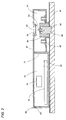
- the atomizing unit 50 includes a flat rectangular casing 60 with a front wall 61 and a rear wall 62 spaced from each other to define therebetween a mist chamber 70 and a driver chamber 72 which is hermetically closed chamber separated from the mist chamber 70 by a dividing wall 71.
- the bottom wall 62 has an opening 65 for detachably receiving a frame 80 which carries an emitter electrode 52 projecting into the mist chamber 70 towards an outlet 64 formed in the front wall 61.
- An opposed electrode 54 of ring-shape is supported to the front wall 61 around the outlet 64 in an opposed relation to the front end of the emitter electrode 52.
- the casing 60 and the frame 80 are made of a dielectric plastic material, while the emitter electrode 52 and the opposed electrode 54 are made of an electrically conductive metallic material.
- the emitter electrode 52 has its rear end connected to and surrounded by a cooling coupler 90 which is made of a metal having a good thermal conductivity into a cylindrical shape fitted within the center of the frame 80.
- the cooling coupler 90 is formed in its front end with a cavity 92 through with the emitter electrode 52 projects with its rear end embedded into the cooling coupler 90 and with a middle portion being spaced from a side wall of the cavity 92 .
- the cooling coupler 90 has its rear end projecting out through the rear wall 62 of the casing 60 to establish a thermal bridge between the cold space 30 and the emitter electrode 52 for cooling the emitter electrode 52 by making the use of the cold air flowing in the cold space 30, thereby condensing water from within surrounding air so as to constantly supply the water on the emitter electrode 52.
- the atomizing unit 50 includes a high voltage source 74 which applies a high voltage between the emitter electrode 52 and the opposed electrode 54 to atomize the water on the emitter electrode 52 into the charged minute water particles and therefore generate the mist of the particles from the front end of the emitter electrode 52 towards and through the opposed electrode 54, thereby discharging the mist through the outlet port 64 out of the casing 60 into the vegetable room 24.
- the high voltage source 74 is controlled by a controller 76 to apply the high voltage at a controlled manner for generating and discharging the mist into the vegetable room 24 continuously or at variable intervals.
- the emitter electrode 52 is fitted with a terminal 53 on the bottom of the cavity 92 for electrical connection with the high voltage source 74, while the opposed electrode 54 is provided on its outer periphery with a terminal 55 for electrical connection with the high voltage source 74.
- the high voltage source 74 and the controller 76 are accommodated within the driver chamber 72 isolated from the mist chamber 70.
- the high voltage source 74 is configured to apply 5 kV to the opposed electrode 54 with the emitter electrode 52 being held in a ground potential or 0 V, so as to generate negatively charged minute water particles having a diameter in the order of nanometers at the front end of the emitter electrode 52.
- the high voltage difference causes the water at the tip of the emitter electrode 52 to develop a Taylor cone (T), as shown in FIG. 4 .
- T the Taylor cone
- the electric charge becomes concentrated to a tip of the cone to thereby further increase electric field strength, which causes the cone to grow further with increased concentration of the charge at the tip of the cone.
- an increased energy is applied to the tip of the cone to cause Rayleigh disintegration to atomize the cone into the charged minute water particles in the order of nanometers.
- the negatively charged minute water particles (W) are driven to move through the opposed electrode 54 because of its relatively large mass and therefore of large inertia force, thereby reaching and adhering on the wall of the vegetable room 24 as well as the contents (C) stored therein for effective deodorization and sterilization.
- the atomizing unit 50 is mounted on the partition 44 with its rear wall adhered thereto to communicate the outlet 64 with the interior of the vegetable room 24 for introducing the air of the vegetable room 24 into the mist space 70 as well as discharging the mist into the vegetable room 24.
- the partition 44 is formed in its surface opposing the vegetable space 24 with a recess 48 which in turn forms a reduced-thickness portion in the partition 44.
- the rear end of the cooling coupler 90 is fitted in the recess 48 and comes into a heat transfer relation with the cold space 30 through the reduced-thickness portion so as to establish the thermal bridge between the cold space 30 and the emitter electrode 52.
- the depth of the recess 48 is selected to give an optimum temperature difference between the cooling coupler 90 and the cold space 30 sufficient for cooling the emitter electrode 52 while keeping an intended thermal insulation between the cold space 30 and the vegetable room 24.
- the partition 44 is made of a thermally insulating material and is covered with a sheath 45 except at the recess 48..
- the cooling coupler 90 is shaped to have a larger volume or thermal capacity than the emitter electrode 52 so as to keep cooling the emitter electrode for successive condensation of the water thereon.
- the water is condensed on a middle portion of the emitter electrode 52 exposed in the cavity 92 of the cooling coupler 90 and on the front end projecting from the cooling coupler 90.
- the middle portion is confined by the side wall of the cavity 90 in a spaced relation therefrom and can be cooled also from the surrounding wall of the cavity 92.
- the high voltage source 74 and the controller 76 are isolated away from the cooling coupler 90, and accommodated within the driver chamber 71 separated from the mist chamber 70 so as to be protected from the mist as well as being cooled, and therefore being made moisture-free for reliable electrical operation over a long period of use.
- FIG. 5 shows a modification of the atomizing unit which is additionally provided with a heating jacket 100 disposed on the rear end of the frame 80 to surround the cooling coupler 90 between the partition 44 and the frame 80.
- the other configurations are identical to the above embodiment. Therefore, like parts are designated by like reference numerals, and no duplicate explanation is made herein.
- the heating jacket 100 is introduced to heat the cooling coupler 90 when the cooling coupler 90 is over-cooled to such an extent of condensing excessive amount of water or freezing the water on the emitter electrode 52.
- the atomizing unit 50 includes a first temperature sensor 101 provided on the partition 44 for sensing temperature of the cold space 30, a second sensor 102 and a humid sensor 103 respectively provided on the front wall 61 for sensing temperature and humidity of the vegetable room 24. Outputs of these sensors are received at the controller 76 which is configured to determine an optimum temperature to which the emitter electrode 52 is cooled for condensing sufficient amount of water to generate the mist successfully, and to keep the temperature of the cooling coupler 90 around the optimum temperature by activating the heating jacket 100.
- the temperature and humidity of the vegetable room 24 vary due to frequent door opening and/or varying environment. As a result, there may sometimes occur a considerable temperature difference between the cold space 30 and the vegetable room 24 which would cause excessive cooling of the emitter electrode 52 to condense excessive amount of water or even freeze the water. When this occurs, i.e., the temperature difference exceeds a critical level, the controller 76 responds to activate the heating jacket 100 so as to heat the emitter electrode 52 to the optimum temperature, thereby enabling to keep generating the mist successfully.
- the optimum temperature and the critical level are constantly updated at the controller 76 in consideration of varying temperatures of the cold space 30 and the vegetable room 24, and also relative humidity of the vegetable room 24.
- FIG. 6 shows an atomizing unit 50 in accordance with a second embodiment of the present invention which is identical to the above embodiment except that the emitter electrode 52 is elongated to define at its rear end the cooling coupler 90A.
- the like parts are designated by like reference numerals, and no duplicate explanation is deemed necessary.
- the emitter electrode 52 extends through a cooling jacket 90B held within the frame 80 to have its front end project out of the frame 80.
- the rear end of the emitter electrode 52, i.e., the cooling coupler 90A projects out of the cooling jacket 90B and the bottom wall 62 of the casing 60 into an associated recess 48A in the surface of the partition 44 for establishing a heat transfer relation with the cold space 30 through the reduced-thickness portion of the partition 44.
- the cooling jacket 90B is made of a heat conductive metallic material into a cylindrical shape surrounding the emitter electrode 52 within the frame 80 or within the casing 60.
- the emitter electrode 52 is cooled by the cold air in the cold space to condense the water thereon for generating the mist of the charged minute water particles.
- the cooling jacket 90B has a larger volume than the emitter electrode to serves as a thermal accumulator for effectively cooling the emitter electrode 52.
- the present embodiment may be modified to include the heating jacket 100 and the associated control as mentioned in the above.
- the high voltage source 74 is preferred to apply the high voltage to the opposed electrode 54 with the emitter electrode 52 being connected to the ground potential or near ground potential in order to keep the housing 20 of the appliance free from the high voltage.
- the condensed water is atomized into positively charged minute water particles which are discharged in the form of a mist in the vegetable room, i.e., the temperature-regulated space, while at the same time positive discharged from the emitter electrode are entrapped by the opposed electrode of the ground potential to avoid the electrostatic shock, as is discussed with reference to FIG. 4 .
Landscapes
- Engineering & Computer Science (AREA)
- Chemical & Material Sciences (AREA)
- Life Sciences & Earth Sciences (AREA)
- Physics & Mathematics (AREA)
- Thermal Sciences (AREA)
- Food Science & Technology (AREA)
- Polymers & Plastics (AREA)
- Combustion & Propulsion (AREA)
- Wood Science & Technology (AREA)
- Mechanical Engineering (AREA)
- Zoology (AREA)
- General Engineering & Computer Science (AREA)
- Electrostatic Spraying Apparatus (AREA)
- Cold Air Circulating Systems And Constructional Details In Refrigerators (AREA)
- Thermistors And Varistors (AREA)
- Control Of Temperature (AREA)
- Application Of Or Painting With Fluid Materials (AREA)
- Spray Control Apparatus (AREA)
- Electrostatic Separation (AREA)
Claims (7)
- Eine temperaturregulierende Vorrichtung (10) ausgerüstet mit Kühlmittel (32) und einer elektrostatischen Zerstäubungseinrichtung (50), wobei die Vorrichtung (10) ausgebildet ist, um einem temperaturregulierten Bereich (24) und einen gekühlten Bereich (30), die durch eine Abtrennung (44) getrennt sind, aufzuweisen, wobei der temperaturregulierte Bereich (24) ausgebildet ist, um seine Temperatur durch Luft von dem gekühlten Bereich (30), der durch das Kühlmittel (32) gekühlt wird, zu regulieren, wobei die Zerstäubungseinrichtung (50) umfasst:eine Emitterelektrode (52), die ausgebildet ist, um daran Wasser von einer umgebenden Luft zu kondensieren, wenn sie gekühlt wird;eine Hochspannungsversorgung (74), die ausgebildet ist, um eine Hochspannung an das Wasser auf der Emitterelektrode (52) anzulegen und das Wasser elektrostatisch aufzuladen, um es in einem Nebel von geladenen winzigen Wasserteilchen zu zerstäuben;wobei die Emitterelektrode (52) ausgebildet ist, um ihre Vorderseite dem temperaturregulierten Bereich (24) auszusetzen und ihre Rückseite über die Abtrennung (44) in einem wärmeleitfähigem Zustand mit dem gekühlten Bereich (30) zu halten, um so durch den gekühlten Bereich (30) für das Kondensieren des Wassers auf der Emitterelektrode (52) gekühlt zu werden,wobei die Zerstäubereinrichtung (50) ein Gehäuse (60) mit einer Vorderwand (61) und einer Rückwand (62), die voneinander getrennt sind, aufweist und mit ihrer Rückwand (62) an der Abtrennung (44) angebracht ist, wobei die Vorderwand (61) mit einem Auslass (64) für das Einführen der Luft von dem temperaturregulierten Bereich (24) und für das Freilassen des Nebels in dem temperaturregulierten Bereich (24) ausgebildet ist,dadurch gekennzeichnet, dassder Behälter (60) ausgebildet ist, um die Emitterelektrode (52) und die Hochspannungsversorgung (74) unterzubringen, und die Emitterelektrode (52) mit einem Kühlkoppler (90) ausgerüstet ist, wobei der Kühlkoppler (90) die Rückwand (62) passierend in die Abtrennung (44) hineinragt.
- Temperaturregulierte Vorrichtung nach Anspruch 1, wobei die Abtrennung (44) teilweise mit einem Bereich reduzierter Dicke (48) ausgebildet ist, an dem ein Überstand des Kühlkopplers (90) koppelt.
- Temperaturregulierende Vorrichtung nach Anspruch 2, wobei die Abtrennung (44) an ihrer Oberfläche mit einer Ausnehmung (48) geformt ist, die den Bereich reduzierter Dicke definiert.
- Temperaturregulierende Vorrichtung nach Anspruch 1, wobei die Zerstäubereinheit (50) eine Gegenelektrode (54) aufweist, die mit der Vorderseite der Emitterelektrode (52) in einer entgegengesetzten Relation gehalten wird, wobei die Hochspannungsversorgung (74) ausgebildet ist, um eine Hochspannung zwischen der Emitterelektrode (52) und der Gegenelektrode (54) auszubilden, wobei die Emitterelektrode (52) an einem Potential, das näher dem Massepotential als das von der Gegenelektrode (54) ist, gehalten wird.
- Temperaturregulierende Vorrichtung nach Anspruch 1, wobei die Emitterelektrode (52) in einem Wärmefluss mit einem Heizmantel (100) steht, wobei der Heizmantel (100) ausgebildet ist, um die Emitterelektrode (52) zu erhitzen, wobei die Zerstäubereinheit (50) einen Controller (46) umfasst, der ausgebildet ist, um eine Temperaturdifferenz zwischen dem gekühlten Bereich (30) und dem temperaturregulierten Bereich (24) zu detektieren und um den Heizmantel (100) nur dann zu aktivieren, wenn die Temperaturdifferenz einen vorbestimmten Schwellenwert überschreitet.
- Temperaturregulierende Vorrichtung (10), die mit Kühlmittel (32) und einer elektrostatischen Zerstäubungseinrichtung (50) ausgerüstet ist, wobei die Vorrichtung (10) ausgebildet ist, um einen temperaturregulierten Bereich (24) und einen gekühlten Bereich (30), die durch eine Abtrennung (44) voneinander getrennt sind, aufweist, wobei der temperaturregulierte Bereich (24) ausgebildet ist, um seine Temperatur durch Luft von dem gekühlten Bereich (30) zu regulieren, wobei der gekühlte Bereich (30) durch das Kühlmittel (32) gekühlt ist;
die Zerstäubungseinrichtung (50) umfassend:eine Emitterelektrode (52), die ausgebildet ist, um daran Wasser aus einer umgebenden Luft im Falle einer Kühlung zu kondensieren;eine Hochspannungsquelle (74) die ausgebildet ist, um eine Hochspannung an das Wasser der Emitterelektrode (52) anzulegen und das Wasser für die Zerstäubung in einen Nebel von geladenen winzigen Wasserteilchen elektrostatisch aufzuladen;wobei die Emitterelektrode (52) ausgebildet ist, um ihre Vorderseite dem temperaturregulierten Bereich (24) zuzuwenden und um ihre Rückseite in einem wärmeleitfähigen Zustand mit dem gekühlten Bereich (30) durch die Abtrennung (44) zu halten, um so durch den gekühlten Bereich (30) gekühlt zu werden und so das Wasser auf der Emitterelektrode (52) zu kondensieren, wobei die Zerstäubereinheit (50) ein Gehäuse (60) mit einer Vorderwand (61) und einer Rückwand (62), die voneinander separiert sind, aufweist und mit seiner Rückwand (62) an der Abtrennung (44) angeordnet ist und die Vorderwand (61) mit einem Auslass (64) ausgebildet ist, um Luft aus dem temperaturregulierten Bereich (24) einzulassen und Nebel in dem temperaturregulierten Bereich (24) auszulassen;dadurch gekennzeichnet, dassdas Gehäuse (60) ausgebildet ist, um die Emitterelektrode (52) und die Hochspannungsversorgung (74) unterzubringen und die Emitterelektrode (52) ausgebildet ist, um mit ihr rückwärtiges Ende durch die Rückwand in die Abtrennung (44) hineinzuragen. - Temperaturregulierende Vorrichtung (10) nach Anspruch 6, wobei die Emitterelektrode (52) von einen Kühlmantel (90A) umgeben ist, wobei der Kühlmantel (90A) ein größeres Volumen als die Emitterelektrode (52) aufweist und in dem Gehäuse (60) angeordnet ist.
Applications Claiming Priority (2)
| Application Number | Priority Date | Filing Date | Title |
|---|---|---|---|
| JP2006338879A JP4706630B2 (ja) | 2006-12-15 | 2006-12-15 | 静電霧化装置 |
| PCT/JP2007/074192 WO2008072759A1 (en) | 2006-12-15 | 2007-12-11 | Electrostatically atomizing unit for use in a temperature-regulating appliance |
Publications (2)
| Publication Number | Publication Date |
|---|---|
| EP2091658A1 EP2091658A1 (de) | 2009-08-26 |
| EP2091658B1 true EP2091658B1 (de) | 2010-08-04 |
Family
ID=39217911
Family Applications (1)
| Application Number | Title | Priority Date | Filing Date |
|---|---|---|---|
| EP07850680A Ceased EP2091658B1 (de) | 2006-12-15 | 2007-12-11 | Einheit mit elektrostatischer zerstäubung zur verwendung in einem temperaturregelgerät |
Country Status (8)
| Country | Link |
|---|---|
| US (1) | US8209990B2 (de) |
| EP (1) | EP2091658B1 (de) |
| JP (1) | JP4706630B2 (de) |
| CN (1) | CN101557878B (de) |
| AT (1) | ATE476258T1 (de) |
| DE (1) | DE602007008287D1 (de) |
| TW (1) | TWI342803B (de) |
| WO (1) | WO2008072759A1 (de) |
Cited By (3)
| Publication number | Priority date | Publication date | Assignee | Title |
|---|---|---|---|---|
| JP2010172891A (ja) * | 2010-02-22 | 2010-08-12 | Panasonic Electric Works Co Ltd | 静電霧化装置 |
| JP2011092936A (ja) * | 2010-12-07 | 2011-05-12 | Panasonic Electric Works Co Ltd | 静電霧化装置 |
| DE112008001095B4 (de) * | 2007-04-26 | 2014-02-06 | Panasonic Corporation | Kühlschrank und elektrische Vorrichtung |
Families Citing this family (17)
| Publication number | Priority date | Publication date | Assignee | Title |
|---|---|---|---|---|
| US8015724B2 (en) * | 2004-04-23 | 2011-09-13 | Panasonic Electric Works Co., Ltd. | Heating blower with electrostatic atomizing device |
| JP5113502B2 (ja) | 2007-11-27 | 2013-01-09 | パナソニック株式会社 | 静電霧化装置 |
| JP2010091232A (ja) * | 2008-10-10 | 2010-04-22 | Panasonic Corp | 冷蔵庫 |
| CN103776224B (zh) * | 2009-03-27 | 2016-01-20 | 三菱电机株式会社 | 静电雾化装置、设备、空气调节器以及电冰箱 |
| JP4818399B2 (ja) * | 2009-06-15 | 2011-11-16 | 三菱電機株式会社 | 静電霧化装置及び空気調和機 |
| JP5468330B2 (ja) * | 2009-08-19 | 2014-04-09 | 株式会社東芝 | 冷蔵庫 |
| TWI432687B (zh) * | 2010-03-01 | 2014-04-01 | Toshiba Kk | 冰箱 |
| JP5609457B2 (ja) * | 2010-03-29 | 2014-10-22 | パナソニック株式会社 | 冷蔵庫 |
| TWI481803B (zh) * | 2010-05-27 | 2015-04-21 | Toshiba Kk | 冰箱 |
| USD681571S1 (en) * | 2010-09-29 | 2013-05-07 | Panasonic Corporation | Electrode |
| USD681572S1 (en) * | 2010-09-29 | 2013-05-07 | Panasonic Corporation | Electrode |
| USD682226S1 (en) * | 2010-09-29 | 2013-05-14 | Panasonic Corporation | Electrostatic atomized water particle generating module |
| JP1434985S (de) * | 2011-04-21 | 2015-02-23 | ||
| JP2012207911A (ja) * | 2012-06-25 | 2012-10-25 | Toshiba Corp | 冷蔵庫 |
| JP6052680B2 (ja) * | 2013-10-25 | 2016-12-27 | パナソニックIpマネジメント株式会社 | 有効成分発生装置 |
| JP6500018B2 (ja) * | 2013-11-05 | 2019-04-10 | ザ リージェンツ オブ ザ ユニバーシティ オブ カリフォルニア | 金属酸化物固定グラフェンおよび炭素ナノチューブハイブリッド発泡体 |
| JP6449134B2 (ja) * | 2015-11-18 | 2019-01-09 | 東芝ライフスタイル株式会社 | 冷蔵庫 |
Citations (1)
| Publication number | Priority date | Publication date | Assignee | Title |
|---|---|---|---|---|
| EP2065097A1 (de) * | 2007-11-27 | 2009-06-03 | Panasonic Electric Works Co., Ltd. | Elektrostatischer Zerstäuber und diesen enthaltende Kühlvorrichtung |
Family Cites Families (16)
| Publication number | Priority date | Publication date | Assignee | Title |
|---|---|---|---|---|
| US2248713A (en) * | 1938-06-20 | 1941-07-08 | Frank W Locke | Means for air conditioning |
| CA1042366A (en) * | 1974-07-26 | 1978-11-14 | Michael J. Pilat | Electrostatic scrubbers involving charged liquid sprays and oppositely charged dust particles |
| JPH0255295A (ja) * | 1988-08-18 | 1990-02-23 | Fujitsu Ltd | ダイヤモンドの気相合成装置およびダイヤモンドの気相合成方法 |
| JP2003121058A (ja) * | 2001-10-05 | 2003-04-23 | Sanyo Electric Co Ltd | 冷蔵庫 |
| JP4232542B2 (ja) * | 2003-06-04 | 2009-03-04 | パナソニック電工株式会社 | 静電霧化装置及びこれを備えた加湿装置 |
| JP4016934B2 (ja) * | 2003-10-30 | 2007-12-05 | 松下電工株式会社 | 静電霧化装置 |
| DE602005012248D1 (de) | 2004-04-08 | 2009-02-26 | Matsushita Electric Works Ltd | Elektrostatischer zerstäuber |
| JP4625267B2 (ja) * | 2004-04-08 | 2011-02-02 | パナソニック電工株式会社 | 静電霧化装置 |
| EP1733798B8 (de) | 2004-04-08 | 2012-02-15 | Panasonic Electric Works Co., Ltd. | Elektrostatischer zerstäuber |
| JP4400523B2 (ja) * | 2004-07-22 | 2010-01-20 | パナソニック株式会社 | 冷蔵庫 |
| WO2006009189A1 (ja) * | 2004-07-22 | 2006-01-26 | Matsushita Electric Industrial Co., Ltd. | 収納庫およびそれを有する冷蔵庫 |
| JP2006057992A (ja) * | 2004-07-22 | 2006-03-02 | Matsushita Electric Ind Co Ltd | 冷蔵庫 |
| WO2006009190A1 (ja) * | 2004-07-22 | 2006-01-26 | Matsushita Electric Industrial Co., Ltd. | 収納庫とそれを用いた冷蔵庫 |
| JP3952052B2 (ja) | 2004-09-06 | 2007-08-01 | 松下電工株式会社 | 静電霧化装置 |
| JP4742892B2 (ja) * | 2005-02-07 | 2011-08-10 | パナソニック株式会社 | 冷蔵庫 |
| JP4799143B2 (ja) | 2005-11-18 | 2011-10-26 | 株式会社日本クライメイトシステムズ | 空調装置 |
-
2006
- 2006-12-15 JP JP2006338879A patent/JP4706630B2/ja active Active
-
2007
- 2007-12-11 AT AT07850680T patent/ATE476258T1/de not_active IP Right Cessation
- 2007-12-11 EP EP07850680A patent/EP2091658B1/de not_active Ceased
- 2007-12-11 WO PCT/JP2007/074192 patent/WO2008072759A1/en not_active Ceased
- 2007-12-11 CN CN200780046375XA patent/CN101557878B/zh not_active Expired - Fee Related
- 2007-12-11 DE DE602007008287T patent/DE602007008287D1/de active Active
- 2007-12-11 US US12/518,880 patent/US8209990B2/en not_active Expired - Fee Related
- 2007-12-12 TW TW096147403A patent/TWI342803B/zh not_active IP Right Cessation
Patent Citations (1)
| Publication number | Priority date | Publication date | Assignee | Title |
|---|---|---|---|---|
| EP2065097A1 (de) * | 2007-11-27 | 2009-06-03 | Panasonic Electric Works Co., Ltd. | Elektrostatischer Zerstäuber und diesen enthaltende Kühlvorrichtung |
Cited By (5)
| Publication number | Priority date | Publication date | Assignee | Title |
|---|---|---|---|---|
| DE112008001095B4 (de) * | 2007-04-26 | 2014-02-06 | Panasonic Corporation | Kühlschrank und elektrische Vorrichtung |
| DE112008002167B4 (de) | 2007-04-26 | 2014-02-06 | Panasonic Corporation | Kühlschrank und elektrische Vorrichtung |
| DE112008002168B4 (de) | 2007-04-26 | 2014-02-13 | Panasonic Corporation | Kühlschrank und elektrische Vorrichtung |
| JP2010172891A (ja) * | 2010-02-22 | 2010-08-12 | Panasonic Electric Works Co Ltd | 静電霧化装置 |
| JP2011092936A (ja) * | 2010-12-07 | 2011-05-12 | Panasonic Electric Works Co Ltd | 静電霧化装置 |
Also Published As
| Publication number | Publication date |
|---|---|
| CN101557878B (zh) | 2011-08-24 |
| ATE476258T1 (de) | 2010-08-15 |
| HK1134663A1 (en) | 2010-05-07 |
| TWI342803B (en) | 2011-06-01 |
| JP4706630B2 (ja) | 2011-06-22 |
| EP2091658A1 (de) | 2009-08-26 |
| US8209990B2 (en) | 2012-07-03 |
| US20100000240A1 (en) | 2010-01-07 |
| TW200900158A (en) | 2009-01-01 |
| JP2008149242A (ja) | 2008-07-03 |
| DE602007008287D1 (de) | 2010-09-16 |
| CN101557878A (zh) | 2009-10-14 |
| WO2008072759A1 (en) | 2008-06-19 |
Similar Documents
| Publication | Publication Date | Title |
|---|---|---|
| US8209990B2 (en) | Electrostatically atomizing unit for use in a temperature-regulating appliance | |
| US7874503B2 (en) | Electrostatcially atomizing device | |
| CN100475353C (zh) | 静电雾化装置 | |
| EP2091660B1 (de) | Elektrostatischer zerstäuber | |
| EP2450649B1 (de) | Kühlschrank | |
| EP2094393B1 (de) | Elektrostatischer zerstäuber | |
| EP2218988B1 (de) | Kühlvorrichtung | |
| JP5113502B2 (ja) | 静電霧化装置 | |
| WO2011121892A1 (ja) | 冷蔵庫及び静電霧化装置 | |
| CN103119384A (zh) | 雾化装置的控制方法、放电装置的控制方法和冷藏库 | |
| JP5200052B2 (ja) | 静電霧化における帯電低減方法及び静電霧化装置 | |
| HK1134663B (en) | Electrostatically atomizing unit for use in a temperature-regulating appliance | |
| JP5097261B2 (ja) | 静電霧化装置 | |
| TWI449873B (zh) | 冰箱 | |
| JP2010172891A (ja) | 静電霧化装置 | |
| JP5239455B2 (ja) | 冷蔵庫 | |
| HK1103048B (en) | Electrostatically atomizing device |
Legal Events
| Date | Code | Title | Description |
|---|---|---|---|
| PUAI | Public reference made under article 153(3) epc to a published international application that has entered the european phase |
Free format text: ORIGINAL CODE: 0009012 |
|
| 17P | Request for examination filed |
Effective date: 20090615 |
|
| AK | Designated contracting states |
Kind code of ref document: A1 Designated state(s): AT BE BG CH CY CZ DE DK EE ES FI FR GB GR HU IE IS IT LI LT LU LV MC MT NL PL PT RO SE SI SK TR |
|
| GRAP | Despatch of communication of intention to grant a patent |
Free format text: ORIGINAL CODE: EPIDOSNIGR1 |
|
| DAX | Request for extension of the european patent (deleted) | ||
| GRAS | Grant fee paid |
Free format text: ORIGINAL CODE: EPIDOSNIGR3 |
|
| GRAA | (expected) grant |
Free format text: ORIGINAL CODE: 0009210 |
|
| AK | Designated contracting states |
Kind code of ref document: B1 Designated state(s): AT BE BG CH CY CZ DE DK EE ES FI FR GB GR HU IE IS IT LI LT LU LV MC MT NL PL PT RO SE SI SK TR |
|
| REG | Reference to a national code |
Ref country code: GB Ref legal event code: FG4D |
|
| REG | Reference to a national code |
Ref country code: CH Ref legal event code: EP |
|
| REG | Reference to a national code |
Ref country code: IE Ref legal event code: FG4D |
|
| REF | Corresponds to: |
Ref document number: 602007008287 Country of ref document: DE Date of ref document: 20100916 Kind code of ref document: P |
|
| REG | Reference to a national code |
Ref country code: NL Ref legal event code: VDEP Effective date: 20100804 |
|
| LTIE | Lt: invalidation of european patent or patent extension |
Effective date: 20100804 |
|
| PG25 | Lapsed in a contracting state [announced via postgrant information from national office to epo] |
Ref country code: NL Free format text: LAPSE BECAUSE OF FAILURE TO SUBMIT A TRANSLATION OF THE DESCRIPTION OR TO PAY THE FEE WITHIN THE PRESCRIBED TIME-LIMIT Effective date: 20100804 Ref country code: LT Free format text: LAPSE BECAUSE OF FAILURE TO SUBMIT A TRANSLATION OF THE DESCRIPTION OR TO PAY THE FEE WITHIN THE PRESCRIBED TIME-LIMIT Effective date: 20100804 Ref country code: FI Free format text: LAPSE BECAUSE OF FAILURE TO SUBMIT A TRANSLATION OF THE DESCRIPTION OR TO PAY THE FEE WITHIN THE PRESCRIBED TIME-LIMIT Effective date: 20100804 Ref country code: AT Free format text: LAPSE BECAUSE OF FAILURE TO SUBMIT A TRANSLATION OF THE DESCRIPTION OR TO PAY THE FEE WITHIN THE PRESCRIBED TIME-LIMIT Effective date: 20100804 |
|
| PG25 | Lapsed in a contracting state [announced via postgrant information from national office to epo] |
Ref country code: PL Free format text: LAPSE BECAUSE OF FAILURE TO SUBMIT A TRANSLATION OF THE DESCRIPTION OR TO PAY THE FEE WITHIN THE PRESCRIBED TIME-LIMIT Effective date: 20100804 Ref country code: SI Free format text: LAPSE BECAUSE OF FAILURE TO SUBMIT A TRANSLATION OF THE DESCRIPTION OR TO PAY THE FEE WITHIN THE PRESCRIBED TIME-LIMIT Effective date: 20100804 Ref country code: BG Free format text: LAPSE BECAUSE OF FAILURE TO SUBMIT A TRANSLATION OF THE DESCRIPTION OR TO PAY THE FEE WITHIN THE PRESCRIBED TIME-LIMIT Effective date: 20101104 Ref country code: CY Free format text: LAPSE BECAUSE OF FAILURE TO SUBMIT A TRANSLATION OF THE DESCRIPTION OR TO PAY THE FEE WITHIN THE PRESCRIBED TIME-LIMIT Effective date: 20100804 Ref country code: IS Free format text: LAPSE BECAUSE OF FAILURE TO SUBMIT A TRANSLATION OF THE DESCRIPTION OR TO PAY THE FEE WITHIN THE PRESCRIBED TIME-LIMIT Effective date: 20101204 Ref country code: PT Free format text: LAPSE BECAUSE OF FAILURE TO SUBMIT A TRANSLATION OF THE DESCRIPTION OR TO PAY THE FEE WITHIN THE PRESCRIBED TIME-LIMIT Effective date: 20101206 |
|
| PG25 | Lapsed in a contracting state [announced via postgrant information from national office to epo] |
Ref country code: GR Free format text: LAPSE BECAUSE OF FAILURE TO SUBMIT A TRANSLATION OF THE DESCRIPTION OR TO PAY THE FEE WITHIN THE PRESCRIBED TIME-LIMIT Effective date: 20101105 Ref country code: LV Free format text: LAPSE BECAUSE OF FAILURE TO SUBMIT A TRANSLATION OF THE DESCRIPTION OR TO PAY THE FEE WITHIN THE PRESCRIBED TIME-LIMIT Effective date: 20100804 Ref country code: SE Free format text: LAPSE BECAUSE OF FAILURE TO SUBMIT A TRANSLATION OF THE DESCRIPTION OR TO PAY THE FEE WITHIN THE PRESCRIBED TIME-LIMIT Effective date: 20100804 Ref country code: BE Free format text: LAPSE BECAUSE OF FAILURE TO SUBMIT A TRANSLATION OF THE DESCRIPTION OR TO PAY THE FEE WITHIN THE PRESCRIBED TIME-LIMIT Effective date: 20100804 |
|
| PGFP | Annual fee paid to national office [announced via postgrant information from national office to epo] |
Ref country code: TR Payment date: 20101123 Year of fee payment: 4 |
|
| PG25 | Lapsed in a contracting state [announced via postgrant information from national office to epo] |
Ref country code: DK Free format text: LAPSE BECAUSE OF FAILURE TO SUBMIT A TRANSLATION OF THE DESCRIPTION OR TO PAY THE FEE WITHIN THE PRESCRIBED TIME-LIMIT Effective date: 20100804 |
|
| PG25 | Lapsed in a contracting state [announced via postgrant information from national office to epo] |
Ref country code: RO Free format text: LAPSE BECAUSE OF FAILURE TO SUBMIT A TRANSLATION OF THE DESCRIPTION OR TO PAY THE FEE WITHIN THE PRESCRIBED TIME-LIMIT Effective date: 20100804 Ref country code: CZ Free format text: LAPSE BECAUSE OF FAILURE TO SUBMIT A TRANSLATION OF THE DESCRIPTION OR TO PAY THE FEE WITHIN THE PRESCRIBED TIME-LIMIT Effective date: 20100804 Ref country code: EE Free format text: LAPSE BECAUSE OF FAILURE TO SUBMIT A TRANSLATION OF THE DESCRIPTION OR TO PAY THE FEE WITHIN THE PRESCRIBED TIME-LIMIT Effective date: 20100804 Ref country code: SK Free format text: LAPSE BECAUSE OF FAILURE TO SUBMIT A TRANSLATION OF THE DESCRIPTION OR TO PAY THE FEE WITHIN THE PRESCRIBED TIME-LIMIT Effective date: 20100804 |
|
| PLBE | No opposition filed within time limit |
Free format text: ORIGINAL CODE: 0009261 |
|
| STAA | Information on the status of an ep patent application or granted ep patent |
Free format text: STATUS: NO OPPOSITION FILED WITHIN TIME LIMIT |
|
| PG25 | Lapsed in a contracting state [announced via postgrant information from national office to epo] |
Ref country code: ES Free format text: LAPSE BECAUSE OF FAILURE TO SUBMIT A TRANSLATION OF THE DESCRIPTION OR TO PAY THE FEE WITHIN THE PRESCRIBED TIME-LIMIT Effective date: 20101115 |
|
| 26N | No opposition filed |
Effective date: 20110506 |
|
| PG25 | Lapsed in a contracting state [announced via postgrant information from national office to epo] |
Ref country code: MC Free format text: LAPSE BECAUSE OF NON-PAYMENT OF DUE FEES Effective date: 20101231 |
|
| REG | Reference to a national code |
Ref country code: DE Ref legal event code: R097 Ref document number: 602007008287 Country of ref document: DE Effective date: 20110506 |
|
| PG25 | Lapsed in a contracting state [announced via postgrant information from national office to epo] |
Ref country code: IE Free format text: LAPSE BECAUSE OF NON-PAYMENT OF DUE FEES Effective date: 20101211 |
|
| PG25 | Lapsed in a contracting state [announced via postgrant information from national office to epo] |
Ref country code: MT Free format text: LAPSE BECAUSE OF FAILURE TO SUBMIT A TRANSLATION OF THE DESCRIPTION OR TO PAY THE FEE WITHIN THE PRESCRIBED TIME-LIMIT Effective date: 20100804 Ref country code: IT Free format text: LAPSE BECAUSE OF NON-PAYMENT OF DUE FEES Effective date: 20101211 |
|
| REG | Reference to a national code |
Ref country code: CH Ref legal event code: PL |
|
| PG25 | Lapsed in a contracting state [announced via postgrant information from national office to epo] |
Ref country code: LU Free format text: LAPSE BECAUSE OF NON-PAYMENT OF DUE FEES Effective date: 20101211 Ref country code: HU Free format text: LAPSE BECAUSE OF FAILURE TO SUBMIT A TRANSLATION OF THE DESCRIPTION OR TO PAY THE FEE WITHIN THE PRESCRIBED TIME-LIMIT Effective date: 20110205 |
|
| PG25 | Lapsed in a contracting state [announced via postgrant information from national office to epo] |
Ref country code: CH Free format text: LAPSE BECAUSE OF NON-PAYMENT OF DUE FEES Effective date: 20111231 Ref country code: LI Free format text: LAPSE BECAUSE OF NON-PAYMENT OF DUE FEES Effective date: 20111231 |
|
| PGFP | Annual fee paid to national office [announced via postgrant information from national office to epo] |
Ref country code: DE Payment date: 20131204 Year of fee payment: 7 |
|
| PG25 | Lapsed in a contracting state [announced via postgrant information from national office to epo] |
Ref country code: TR Free format text: LAPSE BECAUSE OF NON-PAYMENT OF DUE FEES Effective date: 20121211 |
|
| REG | Reference to a national code |
Ref country code: DE Ref legal event code: R119 Ref document number: 602007008287 Country of ref document: DE |
|
| PG25 | Lapsed in a contracting state [announced via postgrant information from national office to epo] |
Ref country code: DE Free format text: LAPSE BECAUSE OF NON-PAYMENT OF DUE FEES Effective date: 20150701 |
|
| REG | Reference to a national code |
Ref country code: FR Ref legal event code: PLFP Year of fee payment: 9 |
|
| REG | Reference to a national code |
Ref country code: FR Ref legal event code: PLFP Year of fee payment: 10 |
|
| REG | Reference to a national code |
Ref country code: FR Ref legal event code: PLFP Year of fee payment: 11 |
|
| PGFP | Annual fee paid to national office [announced via postgrant information from national office to epo] |
Ref country code: GB Payment date: 20181205 Year of fee payment: 12 Ref country code: FR Payment date: 20181120 Year of fee payment: 12 |
|
| PGFP | Annual fee paid to national office [announced via postgrant information from national office to epo] |
Ref country code: IT Payment date: 20181220 Year of fee payment: 12 |
|
| GBPC | Gb: european patent ceased through non-payment of renewal fee |
Effective date: 20191211 |
|
| PG25 | Lapsed in a contracting state [announced via postgrant information from national office to epo] |
Ref country code: FR Free format text: LAPSE BECAUSE OF NON-PAYMENT OF DUE FEES Effective date: 20191231 Ref country code: IT Free format text: LAPSE BECAUSE OF NON-PAYMENT OF DUE FEES Effective date: 20191211 Ref country code: GB Free format text: LAPSE BECAUSE OF NON-PAYMENT OF DUE FEES Effective date: 20191211 |