EP2091673B1 - Elektromagnetische behandlung von kontaminierten materialien - Google Patents
Elektromagnetische behandlung von kontaminierten materialien Download PDFInfo
- Publication number
- EP2091673B1 EP2091673B1 EP07824569.3A EP07824569A EP2091673B1 EP 2091673 B1 EP2091673 B1 EP 2091673B1 EP 07824569 A EP07824569 A EP 07824569A EP 2091673 B1 EP2091673 B1 EP 2091673B1
- Authority
- EP
- European Patent Office
- Prior art keywords
- oil
- treatment
- cavity
- feed material
- water content
- Prior art date
- Legal status (The legal status is an assumption and is not a legal conclusion. Google has not performed a legal analysis and makes no representation as to the accuracy of the status listed.)
- Active
Links
Images


Classifications
-
- B—PERFORMING OPERATIONS; TRANSPORTING
- B09—DISPOSAL OF SOLID WASTE; RECLAMATION OF CONTAMINATED SOIL
- B09C—RECLAMATION OF CONTAMINATED SOIL
- B09C1/00—Reclamation of contaminated soil
- B09C1/005—Extraction of vapours or gases using vacuum or venting
-
- B—PERFORMING OPERATIONS; TRANSPORTING
- B09—DISPOSAL OF SOLID WASTE; RECLAMATION OF CONTAMINATED SOIL
- B09C—RECLAMATION OF CONTAMINATED SOIL
- B09C1/00—Reclamation of contaminated soil
- B09C1/06—Reclamation of contaminated soil thermally
-
- C—CHEMISTRY; METALLURGY
- C01—INORGANIC CHEMISTRY
- C01G—COMPOUNDS CONTAINING METALS NOT COVERED BY SUBCLASSES C01D OR C01F
- C01G1/00—Methods of preparing compounds of metals not covered by subclasses C01B, C01C, C01D, or C01F, in general
-
- C—CHEMISTRY; METALLURGY
- C10—PETROLEUM, GAS OR COKE INDUSTRIES; TECHNICAL GASES CONTAINING CARBON MONOXIDE; FUELS; LUBRICANTS; PEAT
- C10G—CRACKING HYDROCARBON OILS; PRODUCTION OF LIQUID HYDROCARBON MIXTURES, e.g. BY DESTRUCTIVE HYDROGENATION, OLIGOMERISATION, POLYMERISATION; RECOVERY OF HYDROCARBON OILS FROM OIL-SHALE, OIL-SAND, OR GASES; REFINING MIXTURES MAINLY CONSISTING OF HYDROCARBONS; REFORMING OF NAPHTHA; MINERAL WAXES
- C10G1/00—Production of liquid hydrocarbon mixtures from oil-shale, oil-sand, or non-melting solid carbonaceous or similar materials, e.g. wood, coal
- C10G1/04—Production of liquid hydrocarbon mixtures from oil-shale, oil-sand, or non-melting solid carbonaceous or similar materials, e.g. wood, coal by extraction
-
- E—FIXED CONSTRUCTIONS
- E21—EARTH OR ROCK DRILLING; MINING
- E21B—EARTH OR ROCK DRILLING; OBTAINING OIL, GAS, WATER, SOLUBLE OR MELTABLE MATERIALS OR A SLURRY OF MINERALS FROM WELLS
- E21B21/00—Methods or apparatus for flushing boreholes, e.g. by use of exhaust air from motor
- E21B21/06—Arrangements for treating drilling fluids outside the borehole
- E21B21/063—Arrangements for treating drilling fluids outside the borehole by separating components
- E21B21/065—Separating solids from drilling fluids
- E21B21/066—Separating solids from drilling fluids with further treatment of the solids, e.g. for disposal
-
- C—CHEMISTRY; METALLURGY
- C10—PETROLEUM, GAS OR COKE INDUSTRIES; TECHNICAL GASES CONTAINING CARBON MONOXIDE; FUELS; LUBRICANTS; PEAT
- C10G—CRACKING HYDROCARBON OILS; PRODUCTION OF LIQUID HYDROCARBON MIXTURES, e.g. BY DESTRUCTIVE HYDROGENATION, OLIGOMERISATION, POLYMERISATION; RECOVERY OF HYDROCARBON OILS FROM OIL-SHALE, OIL-SAND, OR GASES; REFINING MIXTURES MAINLY CONSISTING OF HYDROCARBONS; REFORMING OF NAPHTHA; MINERAL WAXES
- C10G2300/00—Aspects relating to hydrocarbon processing covered by groups C10G1/00 - C10G99/00
- C10G2300/80—Additives
- C10G2300/805—Water
Definitions
- the invention relates to a process and apparatus for the treatment of contaminated materials, for example, hydrocarbon contaminated matrices, using electromagnetic radiation.
- the invention relates particularly, but not exclusively, to the continuous microwave treatment of oil contaminated drill cuttings.
- Electromagnetic radiation includes, inter alia microwave and radio frequency radiation, as well as other frequencies of radiation, such as infra red or visible light.
- 'Hydrocarbon contaminated matrix', or 'oil contaminated matrix' is used herein to mean a matrix, often of solid materials, for example rock chippings, soil, sludge, filter cake, etc, which comprises a water content and which is contaminated with hydrocarbons.
- the hydrocarbons could be any natural or synthetic hydrocarbon, such as natural or synthetic oils.
- the hydrocarbons might be naturally present in the rock.
- An example of an oil contaminated matrix is oil contaminated drill cuttings. Drill cuttings are made up of a mixture of rock fragments, oil and water, and are produced in significant quantity during the exploration and production of oil and gas.
- a bore can be drilled at a rate of between 30 and 50 feet (9,1 and 15,2 m) per hour. Bores are often 3 to 5 km in depth, and can be 83 ⁇ 4inches, 15 inches or 171 ⁇ 4 inches (0,22 m, 0,38 m or 0.44 m) in diameter. It is estimated that the 56 sites in the North Sea alone produce over a million tons of waste drill cuttings per year.
- Drilling muds are generally oil based, especially in difficult drilling conditions such as those experienced in the North Sea. In less challenging geological areas, water based or synthetic drilling muds may be used.
- the oil contaminate in the drill cuttings is mainly derived from the drilling mud itself, rather than naturally occurring oil, and might comprise 5-30% by weight of the cuttings. Whilst the use of water based muds causes less issues in the final disposal of the drill cuttings, as such cuttings have little oil content, oil based muds are necessary when the geological situation demands it, for example where the rock is hard, or where complicated bores are required to be drilled.
- Oil contaminated drill cuttings (sometimes referred to herein as OCDC) produced on off shore oil or gas drilling rigs were historically disposed of by dumping them into the sea.
- OCDC Oil contaminated drill cuttings
- drill cuttings now pose a more difficult disposal problem on rigs, because environmental regulations often mean that they cannot be discharged into the sea. Regulations vary from country to country. For example, current UK regulations require less than 1% oil by weight in drill cuttings for sea disposal.
- oil based drilling muds are themselves relatively high value materials. We consider it desirable to provide a process and apparatus that is able to recover at least a portion of used oil based drilling mud from drill cuttings. The more oil that can be recycled, the less needs to be shipped out to and stored on the rig itself, meaning rigs can run longer without needing to re-supply and at lower cost.
- thermal treatment processes include incineration, thermal desorption or processes where mechanical energy is used to generate heat. In such processes it is normal to heat cuttings to a temperature sufficient to remove any water present in the cuttings, and then raise the temperature until oil contaminant within the cuttings is burnt or boiled away.
- US 5 487 873 discloses methods and apparatus for treating waste with radio frequency, which includes a wall defining a radio frequency treatment chamber through which waste may be passed.
- a source of radio frequency energy energizes the radio frequency treatment chamber to heat the waste and drive off vapours therefrom leaving solid residue to be disposed of.
- WO 93/14821 A discloses a method and apparatus for the controlled non-pyrolytic reduction of organic material comprising subjecting the material to microwave radiation in a reducing atmosphere.
- Optional features are defined in claims 9 to 18.
- FIG. 1 An overview of a system 1 for continuously separating oil from oil contaminated drill cuttings on an offshore oil/gas exploration rig is shown in Figure 1 .
- the system comprises feed means 7 (or a material feeder 7) for feeding a feed material 5 comprising untreated drill cuttings 6 (which comprise a mixture, of water, oil and rock) into a microwave treatment cavity 3.
- Condensing means 9 is provided adjacent the outlet of cavity 3 and is arranged to separate an inert purging, or sweep, gas 11 from a recovered oil and water mixture 13.
- a separator 15 is provided to separate the mixture 13 into oil 14 and water 16.
- An extraction or recirculation system 17 is provided to filter and clean the gas 11 and to return it to the feed inlet 12 of the microwave cavity 3.
- the extraction system 17 comprises a pump 18 to pump the gas 11 through the cavity 3, and a clean gas inlet 20, for introducing new gas to the recirculated gas.
- a feedback system 21 is provided to feed treated cuttings 19 back to handling system 7 as dry, treated material 22.
- the feed material 5 is fed into cavity 3 on a conveyor 10, e.g. a conveyor belt.
- the feed material 5 is exposed to microwave radiation in a treatment area 8 (bounded by broken lines), which (as is described in more detail below) causes rapid and preferential heating of water within the feed material. This in turn causes thermal desorption of the oil component of the feed material, leaving substantially oil-free solid treated drill cuttings 19.
- the gas sweep 11 passing through the cavity 3 aids vapour removal to the condenser 9. Oil recovered by the condenser can be recycled into drilling mud (which may require the addition of some additives) whilst the treated solid material 19 is suitable for disposal (or for a feedback "dry” material 22 for blending back into the feed material 5 to control its water content - see later).
- Treated material has less than 1% by weight of material on the conveyor of oil and can be disposed of directly into the sea.
- a throughput of 5 to 10 tonnes/hour can be achieved, but a throughput within the range of 250kg/hour to 1 tonne/hour is satisfactory for most offshore rigs.
- These sorts of performance can be achieved with a microwave generator having a power of around 100kW, with a power density of over 1W/mm 3 (10 9 W/m 3 ).
- the system is small and compact, allowing it to fit easily onto a rig despite the restricted space.
- An industrial scale model could be simply freighted in an ISO freight container.
- the exact process footprint is variable as the system can be arranged in a large number of ways due to its modular nature, e.g. it could be arranged vertically with minimal use of a horizontal conveyor.
- the feed system could also be relatively far away from the treatment cavity. This flexibility makes it particularly useful on an offshore rig.
- the composition of the feed material and the intensity and uniformity of the electromagnetic radiation (which depends at least in part on the shape of the microwave cavity itself), both influence the effective removal of oil.
- the feed material preparation and feed system 7 and the electromagnetic treatment cavity 3 are both engineered to ensure that contaminated material is consistently and uniformly treated.
- the means for the removal of evolved gases and vapours, optionally to allow those gases to be recovered and recycled is considered separately inventive.
- the treatment method is based on the observation that if water within the material to be treated (e.g. water within the rocks of drill cuttings) is heated rapidly to steam then heat transfer mechanisms heat the oil contaminant resulting in thermal desorption of the oil.
- the water in the rocks is driven out of the rock and carries oil from the surface of the rocks as it goes.
- thermal desorption of oil is due to microwave heating of the water content of the drill cuttings.
- the oil is not directly heated itself by the microwave radiation (or this is not the effect relied upon).
- the solid mineral phases of the drill cuttings generally do not possess dielectric properties that are conducive to microwave heating.
- the contaminating hydrocarbon phases are essentially transparent to the electromagnetic energy so these phases are not heated directly to a significant extent.
- water is a good absorber of electromagnetic energy, and particularly microwave energy.
- the main influence on dielectric properties of the drill cuttings is connected to the water content of the cuttings. In other materials than OCDC other properties might affect the dielectric properties as well as the water content. Properties include rock type, soil type, organic content, organic species, temperature, density, metal content and others.
- particle size influences the bulk properties of the material and may have an influence on the success of any treatment regime.
- Liquid levels within a material to be treated are partly dependent on the mineralogy of the cuttings.
- Water can be present in a material to be treated in a number of forms that can be broadly defined as 'bound' and 'free'. 'Bound' water is contained within the rock fragments themselves, while 'free' water can be considered as external to the rock fragments.
- Promoting cases (a) and (b) is of interest since they inherently require less microwave energy than (c).
- the water content is critical in driving the mechanism for oil removal.
- the cuttings can vary in physical appearance from soil-like to a viscous liquid depending on the liquid content and the particle size.
- the water content also impacts on the agglomerated particle size, thus impacting upon heat and mass transfer within a bed of cuttings.
- the dielectric properties of a material relate to the ability of the material to absorb microwave energy.
- OCDC water is the main microwave absorber, and so the water content (along with the electric field distribution) determines where microwave energy is dissipated within the sample and the extent to which the energy penetrates into its depth.
- Figure 2b shows the measured dielectric properties of drill cuttings from a number of different samples. It can be seen that dielectric properties vary significantly from sample to sample.
- Figure 3 shows the temperature of chalk and sandstone-based drill cuttings samples over time, during microwave treatment in a multimode cavity at 1kW.
- the temperature/time profiles shown are non-linear, and are potentially very interesting.
- a thorough analysis of each region has not yet been conducted, there are a number of general conclusions that can be drawn from the data. Firstly, it is possible to superheat the water in the cuttings to form steam even at very low power levels such as 1kW, a likely consequence of the very low thermal conductivity of the cuttings. Secondly, it can be seen that higher temperatures are achieved much more quickly with the chalk-based cuttings, which is likely to be due to the presence of bound water.
- the rate at which a material is heated depends on a number of factors, including the dielectric properties, and in particular the water content of the material itself, as well as on the power of the radiation that is being applied.
- the power absorption density per unit volume within a load is described by equation (1).
- P d 2 ⁇ . ⁇ . ⁇ o . ⁇ " . E o 2
- the field intensity is controlled to promote thermal desorption rather than pyrolysis so that the oil can be recovered and re-used.
- dry material 23 is blended with the wet cuttings 6 to produce a crumble-like feed material. This is shown schematically in Figure 4 .
- the dry material is in fact treated cuttings 19, and the feed system 7 comprises a feedback means (shown schematically at 21 in Figure 1 ) for recycling dry treated material into the dry material feed 23, as a mechanism to control the properties of the feed material to the system.
- the water content of the untreated cuttings may be measured to assist in controlling the water content of the feed material. If desired, the water content of the treated cuttings may also be measured, although this is not necessary as treated cuttings generally have a low and fairly consistent water content.
- the feedback system may be arranged to adjust the amount of dry material blended into the wet cuttings based on the measured water content of those cuttings.
- the plastic nature of the blended material means it cannot be stored in a static condition without causing deformation of the particles, loss of flowability and reduction of permeability. For this reason a continuous mixer 25 is used to make the process work reliably.
- a double-shaft paddle mixer can be used to blend and mix the two feed components. The mixture is introduced onto a conveyor (see Fig 1 ) and carried into the microwave cavity 3 directly from the mixer 25.
- the drier, fed-back, material is mixed with the wetter, unmicrowaved, material to produce a feed material of substantially uniform bulk composition.
- Two screw feeders 23a and 6a are used to control the flow feed rates of the wet and dry feed components.
- the ratio of wet/dry material in the feed material impacts upon the particle size, and hence the permeability of the feed material.
- permeability we mean the ratio of the non-solid volume (pores and liquid) of the material to the total volume (including the solid and non-solid parts).
- High permeability for example, within the range of 0.3 to 0.6 of the drill cuttings, is beneficial to ensure the oil mist can be expelled from the material and removed through movement of the interstitial air.
- a high permeability also helps to optimise mass transfer.
- a "crumble" type mixture is created by mixing the raw and dried drill cuttings, which produces agglomerated balls of the raw (wet) material surrounded by dry (treated) that achieves an easy flowing and highly gas permeable material with reasonably regular particle size.
- Figure 5 demonstrates that a minimum of 30% dry material should be blended in with wet feed to ensure a feed material in which the majority of particles are of a similar size.
- the 30% is somewhat arbitrary based on the water and oil content of a particular single sample. If the feed is relatively dry, then no back blending would be required. If it is very wet then more blending would be required.
- the exact ratio of wet to dry cuttings will partly depend on the properties of the cuttings themselves.
- the optimum water content of feed material is 3 to 8%, for example 5%, by weight. However water contents in the range 1% to 15% may be acceptable in some circumstances.
- the behaviour of the blended materials when treated with microwaves is equivalent to that of non-mixed cuttings, i.e. the distribution of liquids from the mixing of the wet and dry materials does not adversely affect the ability of the microwave process to remove the oil.
- the sensitivity of the electromagnetic design of the cavity to the dielectric properties of the material justifies the approach to produce a consistent feed material, as both the mass flow rate through the system and the water content of the blended material affect the design of the magnetic cavity.
- the microwave cavity is designed taking into account the dielectric properties of both the feed material and the treated material, as well as the electric field strength required for the treatment of the material.
- the rate of energy input to the material to be treated should be maximised, as it is necessary to convert water to steam as quickly as possible. This is achieved by passing a relatively small stream of material through a zone of, uniform, high electric field strength, resulting in the rapid heating of the water.
- 'uniform' we mean a field of characteristics such that when a stream of material has passed through the field each particle within the stream received substantially the same electromagnetic treatment. That is, material passing through the cavity is substantially uniformly treated. It will be seen that the field itself does not necessarily have a uniform distribution within the treatment area.
- the strength of the electric field should be as high as possible, but not exceed the break down voltage in air. We have used radiation where the magnitude of the electric field portion is approximately 10 7 V/m
- the residence time of the material in the treatment cavity would be from fractions of a second (such as 1/10 th ) to 1 or 10 seconds.
- the residence time in the treatment zone 8 is dependant on the conveyor belt speed.
- the throughput of the process is dependant, to some extent, on the dominant hydrocarbon removal mechanisms in the process (identified earlier).
- the residence time could even be less than 0.1s, for example 0.05 second.
- the electromagnetic power (microwave) applied should be in the range of 5kW to approximately 2MW. Higher powers result in more rapid heating of the water content of the feed material being treated.
- a 'tunnel applicator' is shown schematically in Figure 6 .
- the apparatus comprise a microwave treatment cavity 3 having a waveguide 29 and a self-cancelling step 31.
- the step 31 is arranged to encourage the formation of a more uniform field within treatment zone 8, as is well known.
- a trough belt 27 carries blended feed material into and out of the treatment cavity 3.
- the belt 27 is continuous and returns below the microwave cavity (shown schematically at 28).
- the belt material is such that it can withstand high temperatures, and is reasonably transparent to microwaves.
- the belt is supported on rollers (see Figure 11 ), which are also reasonably transparent to microwaves. Hence substantially the only absorber of radiation within the cavity is the water within the material being treated.
- the belt extends from the cavity on the downstream end for a distance sufficient to allow for vapour recovery, if necessary.
- a trough-belt system is used as it provides many advantages over a flat belt system, which can have material handling problems such as load falling off the belt sides.
- the trough belt also provides the best option in terms of the uniformity of the electric field.
- the cavity 3 is designed to result in the generation of a sufficient electric field strength and effective treatment zone 8, taking into account the properties of the feed material. If the field strength is too low then the energy will not be sufficient to turn the water rapidly into steam. If water is not rapidly heated to steam (for example, in less than 5 seconds) then the oil removal mechanisms described above do not work effectively.
- the microwave emitter may operate continuously, or may be pulsed; either term falls within the bounds of the term 'continuous' as used herein.
- the prevention of localised areas of high field strength and the field uniformity were the parameters used to assess the feasibility of each simulated cavity.
- the field needs only to be sufficiently uniform to provide substantially uniform treatment.
- the conveyor belt does not extend to the edges of the cavity the field need not be uniform beyond the edges of the belt.
- the exact cavity dimensions stem from an iterative simulation process in which the likely effectiveness of different cavity dimensions were assessed.
- the above design was improved by the addition of a self-cancelling reflection step to provide a more uniform field distribution in the vertical plane.
- the step is a quarter of a wavelength deep, resulting in a total of half a wavelength being cancelled out in the step. Due to the reflection of the microwaves multiple hot spots are generated throughout the y-direction ( Figure 7(b) ). The result is the net effect shown in Figure 7(c) , which is more uniform than what can be obtained without a step (which would be closer to the distribution in the area labelled 'B' in Figure 7(c) ). Given that the power in each of the regions A and B is high enough the electric field strength will be strong enough, resulting in uniform treatment of the sample moving through any one region in the z direction for a given residence time. Therefore, for a high power density, the residence time in each region should be relatively small.
- the field does not have to particularly uniform in the y-direction, as long as there is sufficient overlap between all of the hot spots, while in the x-direction then less than 10% variation would be desirable. It is important to note that this field uniformity relates to this type of design. A different cavity design might require different levels of uniformity.
- step optimisation as described above, the following other factors must be considered:
- the cavity also is designed to maximise the headspace above the material being treated to aid removal of the vapours. As much headspace as possible is required, without compromising the power density. Build up of vapours within the system would result in oil and water deposition onto the internal surfaces of the treatment cavity, and possible damage to the cavity.
- a set of chokes incorporated into the whole cavity design, prevents microwave leakage from the applicator from the inlet and outlet of the tunnel.
- the cavity was designed for a feed material of particular dielectric properties.
- the median power density divided by the standard deviation was the key parameter used to differentiate each simulation based on its likely effectiveness.
- the properties chosen in the simulations represent an average for blended drill cuttings, based on the measurements taken of untreated drill cuttings, along with mixing laws and assumptions for the granulated materials.
- Figure 10 illustrates (a) Electric field distribution (M/ ⁇ ) and (b) dissipated power as a function of the belt radius for both design cases for both cases.
- Case 1 (labelled as the improved ideal case design) offers the best performance.
- the field uniformity is adversely affected (as shown by a marked decrease in M / ⁇ , the median power density divided by the standard deviation)
- design Case 2 is the one that should be adopted, as Case 2 tolerates the curvature of the belt in the corners, whereas the alternative design is not very robust in this respect.
- the applied power assumed for the simulations is 0.5W, which indicated that 95% + of the forward power is dissipated within the material without any need for external tuning devices.
- FIG. 8 A perspective view of a laboratory scale tunnel applicator is shown in Figure 8 .
- the step 31 results in a number of areas of well-defined, very even and very high electric field strength by reflecting radiation input using the waveguide 29 in a well known manner.
- a conveyor belt (not shown) passes material through the field at a constant speed, such that the treatment is as even as possible, with no bias towards the centre or edges of the material on the belt.
- the chokes 33 ensure that electromagnetic energy does not escape from the treatment cavity. These chokes are a function of the material in the tunnel and therefore the design of the cavity can be asymmetric to take account of the different material properties on the conveyor belt both pre and post treatment.
- the laboratory scale cavity is approximately 2.2m in length and 100mm in width and height (excluding chokes and waveguide), and is capable of being operated to produce treated cuttings at a rate of 200kg/hour.
- Figures 15 and 16 show photographs of this cavity. Dimensions of the cavity are given in Figures 8a (top section 3a) and 8b (bottom section 3b).
- Figure 11 shows an optimised tunnel applicator for the treatment of drill cuttings. for an industrial scale system. If the degree of sagging between the rollers adversely impacts on the field distribution, the rollers might be replaced with skid plates.
- the cavity has been optimised for specific material dielectric properties, and deviations from those properties in feed material would perturb the electric field irrespective of how careful the design. For this reason the feed material properties are carefully controlled by the feed unit 7.
- the height of material on the conveyor can be adjusted to remedy such variations provided that sufficient cross-sectional area is available for extraction of vapours.
- a sweep gas is advantageous in the transportation of vapours away from the cavity, as described in more detail below.
- any inert gas such as nitrogen, could be employed as a sweep gas instead of steam. Similar results to those shown in Figure 13 were obtained with nitrogen gas. It was found that gas stripping alone achieved only a 20% reduction in oil levels whereas the removal efficiency was in excess of 90% when microwaves were applied.
- the microwave process could be used without a sweep gas, which would lessen the degree of design complexity of an industrial scale system.
- a study was performed whereby microwave energy was applied to a bed of drill cuttings for a set time. Nitrogen sweep gas was introduced to the bed of cuttings after the microwaves had been applied, i.e. the sweep gas passes through hot cuttings.
- Figure 14 shows the results of this experiment, where the residual oil levels are shown against the time for which the sweep gas was applied after microwave treatment ceased. Time zero in Figure 14 corresponds to the application of microwaves only. It can be seen that increasing the length of time after treatment for which sweep gas is applied reduces the residual oil level in treated drill cuttings.
- the sweep gas is inserted both at the materials input to the treatment cavity and along the electromagnetic waveguide (via an input in a side of the cavity (shown at 44 in Fig 17).
- Figure 18 shows the pilot scale gas handling system, 46.
- the input point at the waveguide ensures a positive gas pressure at this point and thereby reduces the potential for hydrocarbon and water phases to condense on the quartz window that acts as a barrier to stop potentially materials damaging the microwave generator. If water were to condense on the quartz window, then that water would heat up as microwaves are applied, and might cause the window to melt.
- the flow of gas down the waveguide also helps to overcome problems with arcing.
- the co-current flow allows for rapid removal of the vapours from the areas of high electric field strength.
- FIG. 12 A schematic gas handling system suitable for use in an industrial version of the process is shown in Figure 12 .
- the system can remove the oil and water vapours from the cavity, promote the continued evolution of vapours after microwave treatment and collect the oil and water for separation. Gas may be removed through perforations in a tunnel wall, such as the roof, as well as at the outlet, shown schematically at 40 in Figure 12 .
- the gas handling systems are designed to be as flexible as possible, to allow the exact pressures and flows required in each practical situation to be determined experimentally for various operating conditions.
- New gas 20 can be added in to the recovered gas 11 at valve 42 if desired.
- An exhaust gas outlet 44 is provided.
- a low pressure drop condenser is placed between the microwave treatment unit and a centrifugal fan to collect the oil and water vapours. With a thermal desorption mechanism the only gas discharged will be nitrogen, which can be recycled or purged.
- a continuous pilot-scale system consists of a 5-30 kW variable power microwave generator, which delivers microwaves at 2.45GHz to a cavity via several sections of WR430 waveguide and an automatic E-H tuner.
- the tuner works by varying the geometry in the E and H planes to match the impedance of the microwaves with that of the cavity, with an algorithm used to vary the geometry so as to minimise the reflected power. Any reflected power is absorbed in a circulator, which uses a cold water load, and this protects the magnetron and power supply from excessive returned microwave energy.
- a stream of cold nitrogen was introduced at 2 1/min down the waveguide entrance to the cavity, which was done to provide a positive pressure and prevent oil and water vapours from passing through the waveguide to the microwave generator.
- Drill cuttings are fed from a feed hopper into a twin shaft mixer, where dry material could be introduced to control the moisture content of the feed to the microwave cavity.
- the mixer deposits the cuttings onto a conveyor belt made from woven NomexTM fibres (other flame resistant materials may be used), and formed into a trough to contain the process material.
- a heated nitrogen stream at 10 1/min was introduced at the material feed to act as a sweep gas, and also to provide an inert atmosphere within the cavity to prevent combustion of the oil vapour.
- a top section of the cavity and chokes contains perforations which permit the withdrawal of evolved vapours whilst containing the microwave field.
- An extraction hood covers the perforated sections and the end of the choking section, and the vapours are drawn through a condenser to recover the oil and water. Dry drill cuttings are discharged at the end of the conveyor belt, and collected for analysis and disposal.
- the oil and moisture contents of the treated and untreated drill cuttings were measured, and used to determine the degree of treatment.
- Water contents were measured using the Dean and Stark method (International standard ASTM D-95), which involves reflux distillation with toluene and separation of the water phase.
- Oil content measurement was carried out using solvent extraction, which is a technique for extracting organics from solid samples with liquid solvents.
- the organics were extracted using Dichloromethane (DCM) at elevated temperatures and pressures to increase the efficiency of the extraction process. Increased temperature accelerates the extraction kinetics, while elevated pressure keeps the solvent below its boiling point, thus enabling safe and rapid extractions.
- the hydrocarbon content of the organic phase was determined using Gas Chromatogram techniques.
- the drill cuttings were obtained from North Sea drilling operations, and contained 10% oil and 10% water. Dry clay was added to reduce the oil and water content of the cuttings to 7%, which altered the consistency of the cuttings from a slurry to a more permeable, agglomerated granular material.
- the throughput of drill cuttings was varied by changing the speed of the conveyor belt.
- the applied power was kept constant at 15kW, and the throughput varied between 110 and 220 kg/hr. This correspond to belt speeds of 10 - 20 mm/s and residence times within the electric field of 5 - 10 seconds.
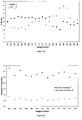
- the bulk residual oil content was determined for each set of conditions, and these results are shown in Figure 20 , which shows the residual oil content plotted against throughput for a constant applied power of 15kW.
- the dotted line represents environmental discharge threshold of 1% oil on cuttings.
- the reflected power levels were again found to be relatively constant across the range of throughputs studied, with values of 0.4 - 0.7 kW recorded. It is postulated that decreasing the throughput below 100 kg/hr at 15kW will result in an increase in the reflected power as the residence time in the microwave cavity is likely to extend beyond that required to remove the water, meaning that the remaining cuttings effectively become microwave transparent.
- the electric field distribution is a strong function of the dielectric constant and dielectric loss factor of the process material. When the water is removed the dielectric loss factor decreases to below 0.1, meaning that much of the 15kW of available microwave power will be transmitted through the material with very little being absorbed.
- the base-oil in the drilling mud was characterised using Gas Chromatography.
- the oil and water recovered from the condenser were collected and the two phases allowed to separate under gravity. Three samples of the oil phase were removed for analysis, and typical results are shown in Figure 21 , which shows Gas Chromatograms of (a) original oil from untreated drill cuttings and (b) recovered oil after microwave treatment.
- the 1% environmental discharge limit can be achieved using around 100 kWh per tonne of drill cuttings.
- Significantly cleaner cuttings can be produced at higher energy inputs of the order of 140 kWh per tonne, which correspond to longer residence times within the microwave field.
- Figure 24 shows the variation of residual oil content with energy input for three processing scenarios utilising 15kW of microwave power.
- the cavity which supports the lowest power density is the multimode cavity, and it can be seen from Figure 24 that the energy requirements are of the order of 450 kWh per tonne to reduce the oil content to 2%.
- the tests in the multimode cavity showed that the 1% discharge threshold is difficult to achieve, and our previous work also supports this observation.
- Table 2 Power densities in multimode, single mode and continuous microwave applicators.
- the single mode cavity supports a power density which is an order of magnitude higher than that in the multimode cavity (see Table 2), and this leads to an increased heating rate.
- the microwave power is dissipated within the water phase, causing superheating of the water and rapid conversion into steam.
- the heating rate is proportionately lower, meaning that the beneficial effects of rapid steam formation are reduced due to heat transfer losses and recondensation of some of the steam before it can act as an entraining gas.
- the average power density supported by the continuous system is 1.4 x 10 8 W/m 3 , which is approximately double that supported by the single mode cavity. It can be seen in Figure 24 that the effect of energy input on oil removal with the two cavities is roughly comparable up to the 1% threshold, but the continuous cavity allows much lower levels of residual oil to be achieved.
- the single mode treatment is a batch process, and the dielectric constant and loss factor of the drill cuttings decrease with time as water is lost. At low oil levels there is a correspondingly small amount of water within the sample, and its dielectric loss factor is low. This means that it is difficult to concentrate sufficient microwave energy into the sample, and results in a high reflected power towards the end of the batch test.
- inventions are equally applicable to removing oil from other contaminated matrices, such as soil.
- the invention may be used to recondition brownfield/ex-industrial sites or reduce pollution on beaches after an oil spill, or remove oil from processed hydrocarbon containing materials.
- the treatment described herein can be used to remove a broad range of organic species such as benzene, diesel, and kerosene derivatives as well as hydrocarbons.
- the treatment system will work very effectively for hydrocarbons up to diesel and kerosene, or similar molecules, and will work to a lesser extent for heavier species.
- the invention is not necessarily limited to removing contaminants.
- the material to be driven off may have always been present - the invention could be used to separate a materials susceptible to separation in this way.
- the invention may be used to obtain either the driven off material, or the material that is left behind.
- the invention could be used to obtain a material driven from a substrate by water to steam expansion, for example oil may be obtained from shale in this way.
Landscapes
- Engineering & Computer Science (AREA)
- Life Sciences & Earth Sciences (AREA)
- Chemical & Material Sciences (AREA)
- Environmental & Geological Engineering (AREA)
- Physics & Mathematics (AREA)
- Geology (AREA)
- Mining & Mineral Resources (AREA)
- Soil Sciences (AREA)
- Oil, Petroleum & Natural Gas (AREA)
- Organic Chemistry (AREA)
- Fluid Mechanics (AREA)
- Geochemistry & Mineralogy (AREA)
- Thermal Sciences (AREA)
- General Life Sciences & Earth Sciences (AREA)
- Mechanical Engineering (AREA)
- Wood Science & Technology (AREA)
- Chemical Kinetics & Catalysis (AREA)
- General Chemical & Material Sciences (AREA)
- Inorganic Chemistry (AREA)
- Processing Of Solid Wastes (AREA)
- Physical Or Chemical Processes And Apparatus (AREA)
- Production Of Liquid Hydrocarbon Mixture For Refining Petroleum (AREA)
- Processing And Handling Of Plastics And Other Materials For Molding In General (AREA)
Claims (18)
- Verfahren zum Abscheiden oder Extrahieren oder Reduzieren eines Kohlenwasserstoffgehalts aus einer mit Kohlenwasserstoff kontaminierten Matrix (6), das die 5 Schritte umfasst des:Steuern eines Wassergehalts eines Zuführmaterials (5), das die mit Kohlenwasserstoff kontaminierte Matrix (6) umfasst;kontinuierliches Fördern des Zuführmaterials (5) in einen Behandlungshohlraum (3);Exponieren des Zuführmaterials (5) in einem Behandlungsbereich (8) des Behandlungshohlraums (3) mit elektromagnetischer Strahlung, die eingerichtet ist, um schnelles Erhitzen mindestens eines Teils des Wassergehalts zu verursachen, um Dampf zu bilden, wobei die schnelle Dampfbildung in thermischer Desorption mindestens eines Teils des Kohlenwasserstoffgehalts aus der Matrix (6) resultiert; undkontinuierliches Entfernen der behandelten Matrix aus dem Behandlungshohlraum (3);wobei die elektromagnetische Strahlung eine Frequenz in dem Bereich von 10 MHz bis 10 GHz aufweist;dadurch gekennzeichnet, dassder Wassergehalt des Zuführmaterials (5) durch Mischen eines Materials mit bekanntem Wassergehalt, das die behandelte Matrix umfasst, mit der mit Kohlenwasserstoff kontaminierten Matrix (6) gesteuert wird.
- Verfahren nach Anspruch 1, das weiter den Schritt des Messens eines Wassergehalts der mit Kohlenwasserstoff kontaminierten Matrix (6) oder des Bulkzuführmaterials umfasst.
- Verfahren nach einem vorstehenden Anspruch, wobei der Wassergehalt des Zuführmaterials (5) derart gesteuert wird, dass die elektrischen Eigenschaften des Zuführmaterials (5) als eine Bulkverbundsubstanz in dem Bereich ε' = 0,1 bis 20 und ε" = 0,25 bis 0,75, vorzugsweise in dem Bereich ε'= 2,5 bis 4,5 und ε "= 0,25 bis 0,75 liegen.
- Verfahren nach Anspruch 3, wobei die dielektrischen Bulkeigenschaften des Zuführmaterials (5) ε' = 3,5 und ε" = 0,5 sind.
- Verfahren nach einem vorstehenden Anspruch, wobei die elektromagnetische Strahlung eine Leistung in dem Bereich von 5 kW bis 20 MW oder 1 MW aufweist.
- Verfahren nach einem vorstehenden Anspruch, wobei das Zuführmaterial (5) mit der elektromagnetischen Strahlung während einer Dauer von bis zu 10 Sekunden, in dem Bereich von 0,1 bis 10 Sekunden oder in dem Bereich von 0,1 bis 2 Sekunden exponiert wird.
- Verfahren nach einem vorstehenden Anspruch, das weiter den Schritt des Durchgehens oder Durchfegens von Inertgas (11) durch den Behandlungshohlraum (3) umfasst, um im Wesentlichen Dämpfe aus dem Behandlungsbereich (8) zu entfernen, wobei die Dämpfe während der Exposition des Zuführmaterials (5) mit der elektromagnetischen Strahlung erzeugt wurden.
- Gerät (1) zum Abscheiden oder Extrahieren oder Reduzieren eines Kohlenwasserstoffgehalts aus einer mit Kohlenwasserstoff kontaminierten Matrix (6), wobei das Gerät (1) einen Behandlungshohlraum (3) umfasst, der eine Materialbehandlungsfläche (8), einen Materialzuführer (7), der bei Verwendung eingerichtet ist, um kontinuierlich ein Zuführmaterial (5) in dem Behandlungsbereich (8) und aus ihm zu fördern, einen Sender elektromagnetischer Strahlung, der bei Verwendung eingerichtet ist, um das Zuführmaterial (5) in dem Behandlungsbereich (8) mit elektromagnetischer Strahlung in dem Frequenzbereich von 10 MHz bis 10 GHz zu exponieren, um rasches Erhitzen mindestens eines Teils eines Wassergehalts der mit Kohlenwasserstoff kontaminierten Matrix (6) zu verursachen, um Dampf zu bilden, um mindestens einen Teil des Kohlenwasserstoffgehalts aus der Matrix (6) zu entfernen,
dadurch gekennzeichnet, dass der Materialzuführer (7) einen Materialmischer (21) umfasst, der eingerichtet ist, um zusätzliches Material in die mit Kohlenwasserstoff kontaminierte Matrix (6) zu mischen, wobei das zusätzliche Material behandelte Matrix mit bekanntem Wassergehalt umfasst, um ein Zuführmaterial (5) mit gesteuertem Wassergehalt bereitzustellen. - Gerät (1) nach Anspruch 8, wobei der Behandlungshohlraum (3) einen Tunnelapplikator umfasst, der einen Einlass und einen Auslass aufweist, und die Behandlung zwischen dem Einlass und dem Auslass liegt.
- Gerät (1) nach Anspruch 9, wobei der Tunnelapplikator einen Hohlleiter (29) umfasst, der eingerichtet ist, um elektromagnetische Strahlung von dem Sender elektromagnetischer Strahlung in den Behandlungsbereich (8) zu lenken.
- Gerät (1) nach Anspruch 9 oder Anspruch 10, wobei der Tunnelapplikator weiter Drosseln umfasst, die eingerichtet sind, um dem Entkommen elektromagnetischer Strahlung aus dem Einlass und dem Auslass zu widerstehen.
- Gerät (1) nach einem der Ansprüche 8 bis 11, wobei der Materialzuführer (7) einen Trogförderer (27) zum Fördern von Zuführmaterial (5) durch den Behandlungshohlraum (3) umfasst.
- Gerät (1) nach Anspruch 12, wobei der Förderer (27) von einer Basiswand des Behandlungshohlraums (3) beabstandet ist.
- Gerät (1) nach einem der Ansprüche 8 bis 13, das weiter einen Gaszirkulationsmechanismus (17) umfasst, der eingerichtet ist, um bei Verwendung Inertgas (11) durch den Behandlungsbereich (3) durchzuführen.
- Gerät (1) nach Anspruch 14, wobei der Gaszirkulationsmechanismus (17) bei Verwendung eingerichtet ist, um Inertgas (11) durch den Behandlungsbereich (3) zu zirkulieren und das Inertgas (11) zurückzugewinnen und wieder zu zirkulieren.
- Gerät (1) nach Anspruch 14 oder 15, wie von Anspruch 10 abhängig, wobei der Gaszirkulationsmechanismus (17) eingerichtet ist, um Inertgas (11) zu dem Tunnelapplikator an dem Einlass und an dem Hohlleiter (29) des Tunnelapplikators einzuführen.
- Gerät (1) nach einem der Ansprüche 14 bis 16, wobei der Gaszirkulationsmechanismus (17) eingerichtet ist, um Gas (11) aus dem Tunnelapplikator durch Perforierungen in einer Wand des Tunnelapplikators zu entfernen.
- Gerät (1) nach einem der Ansprüche 14 bis 17, das weiter einen Abscheider umfasst, der dazu angepasst ist, mindestens etwas Dampf, der in dem Behandlungsbereich (8) erzeugt wird, aus dem Inertgas (11) abzuscheiden.
Applications Claiming Priority (2)
| Application Number | Priority Date | Filing Date | Title |
|---|---|---|---|
| GBGB0622595.7A GB0622595D0 (en) | 2006-11-14 | 2006-11-14 | Electromagnetic treatment of contaminated materials |
| PCT/GB2007/004344 WO2008059240A2 (en) | 2006-11-14 | 2007-11-14 | Electromagnetic treatment of contaminated materials |
Publications (2)
| Publication Number | Publication Date |
|---|---|
| EP2091673A2 EP2091673A2 (de) | 2009-08-26 |
| EP2091673B1 true EP2091673B1 (de) | 2021-07-21 |
Family
ID=37594828
Family Applications (1)
| Application Number | Title | Priority Date | Filing Date |
|---|---|---|---|
| EP07824569.3A Active EP2091673B1 (de) | 2006-11-14 | 2007-11-14 | Elektromagnetische behandlung von kontaminierten materialien |
Country Status (11)
| Country | Link |
|---|---|
| US (1) | US8789583B2 (de) |
| EP (1) | EP2091673B1 (de) |
| CN (1) | CN101641166B (de) |
| AU (1) | AU2007321014B2 (de) |
| CA (1) | CA2669497C (de) |
| DK (1) | DK2091673T3 (de) |
| GB (1) | GB0622595D0 (de) |
| MX (1) | MX2009005083A (de) |
| MY (1) | MY151739A (de) |
| NO (1) | NO346732B1 (de) |
| WO (1) | WO2008059240A2 (de) |
Cited By (1)
| Publication number | Priority date | Publication date | Assignee | Title |
|---|---|---|---|---|
| WO2025244537A1 (en) | 2024-05-24 | 2025-11-27 | Norwegian Technology As | Segmented solid conveyor |
Families Citing this family (19)
| Publication number | Priority date | Publication date | Assignee | Title |
|---|---|---|---|---|
| US9073104B2 (en) | 2008-08-14 | 2015-07-07 | National Oilwell Varco, L.P. | Drill cuttings treatment systems |
| GB0823091D0 (en) | 2008-12-18 | 2009-01-28 | Univ Nottingham | Exfoliating vermiculite and other minerals |
| WO2011038304A1 (en) * | 2009-09-28 | 2011-03-31 | Kmc Oil Tools Bv | Drill cuttings methods and systems |
| US8813875B1 (en) * | 2009-09-28 | 2014-08-26 | Kmc Oil Tools B.V. | Drilling rig with continuous microwave particulate treatment system |
| IT1401134B1 (it) * | 2010-07-19 | 2013-07-12 | Geolog Spa | Sistema e metodo per il condizionamento termico di un fluido in particolare un fango di perforazione |
| GB2498736A (en) | 2012-01-25 | 2013-07-31 | Nov Downhole Eurasia Ltd | Apparatus and method for treating hydrocarbon containing materials |
| CZ304205B6 (cs) * | 2012-04-19 | 2014-01-02 | Ústav Chemických Procesů Akademie Věd České Republiky | Způsob dekontaminace tuhých materiálů |
| CN102826729B (zh) * | 2012-09-13 | 2014-03-26 | 中国石油集团长城钻探工程有限公司 | 油基钻井液废弃物电磁微波处理系统及方法 |
| US9643111B2 (en) | 2013-03-08 | 2017-05-09 | National Oilwell Varco, L.P. | Vector maximizing screen |
| CN105170636B (zh) * | 2015-08-26 | 2017-09-12 | 苏州宏奇锐自动化有限公司 | 一种去除土壤污染物的自动化系统 |
| CN108064191B (zh) * | 2015-09-05 | 2021-07-27 | 特尔姆(鼎科)环境公司 | 使用改进活化剂修复污染土壤和水 |
| NO20151452A1 (en) * | 2015-10-26 | 2017-04-27 | Norwegian Tech As | Method for separation of non-polar organic compounds from a material |
| CN105672918A (zh) * | 2016-01-05 | 2016-06-15 | 西南石油大学 | 一种含油钻屑微波处理工艺 |
| GB2549313A (en) | 2016-04-13 | 2017-10-18 | Nov Downhole Eurasia Ltd | Processing apparatus |
| US20190234202A1 (en) * | 2016-06-22 | 2019-08-01 | Schlumberger Technology Corporation | System and method triangulation and zone management for drilling rig communication coordination |
| RU2702230C1 (ru) * | 2019-02-04 | 2019-10-07 | Федеральное государственное автономное образовательное учреждение высшего образования "Санкт-Петербургский государственный электротехнический университет "ЛЭТИ" им. В.И. Ульянова (Ленина) | Способ вспучивания гидрослюды и устройство для его реализации |
| CN110170514B (zh) * | 2019-07-09 | 2021-03-16 | 北京石油化工学院 | 一种蒸汽耦合微波热处理污染土壤设备 |
| CN110793901B (zh) * | 2019-12-13 | 2022-02-11 | 西南石油大学 | 考虑束缚水的高温高压气藏渗透率流速敏感性测试方法 |
| CN113200667A (zh) * | 2021-04-25 | 2021-08-03 | 宁波诺丁汉新材料研究院有限公司 | 一种微波减压蒸馏污泥干燥装置及干燥方法 |
Family Cites Families (3)
| Publication number | Priority date | Publication date | Assignee | Title |
|---|---|---|---|---|
| AU7662691A (en) * | 1990-03-30 | 1991-10-30 | Iit Research Institute | Method and apparatus for treating hazardous waste or other hydrocarbonaceous material |
| CZ183494A3 (en) * | 1992-01-30 | 1995-02-15 | Emery Microwave Management Inc | Process of non-pyrolytic reduction of organic material and apparatus for making the same |
| US5589599A (en) * | 1994-06-07 | 1996-12-31 | Mcmullen; Frederick G. | Pyrolytic conversion of organic feedstock and waste |
-
2006
- 2006-11-14 GB GBGB0622595.7A patent/GB0622595D0/en not_active Ceased
-
2007
- 2007-11-14 WO PCT/GB2007/004344 patent/WO2008059240A2/en not_active Ceased
- 2007-11-14 MX MX2009005083A patent/MX2009005083A/es active IP Right Grant
- 2007-11-14 CA CA2669497A patent/CA2669497C/en active Active
- 2007-11-14 AU AU2007321014A patent/AU2007321014B2/en active Active
- 2007-11-14 EP EP07824569.3A patent/EP2091673B1/de active Active
- 2007-11-14 DK DK07824569.3T patent/DK2091673T3/da active
- 2007-11-14 MY MYPI20091972 patent/MY151739A/en unknown
- 2007-11-14 US US12/514,983 patent/US8789583B2/en active Active
- 2007-11-14 NO NO20092253A patent/NO346732B1/no unknown
- 2007-11-14 CN CN2007800479974A patent/CN101641166B/zh active Active
Non-Patent Citations (1)
| Title |
|---|
| None * |
Cited By (1)
| Publication number | Priority date | Publication date | Assignee | Title |
|---|---|---|---|---|
| WO2025244537A1 (en) | 2024-05-24 | 2025-11-27 | Norwegian Technology As | Segmented solid conveyor |
Also Published As
| Publication number | Publication date |
|---|---|
| MX2009005083A (es) | 2009-10-13 |
| CN101641166B (zh) | 2012-11-14 |
| CA2669497C (en) | 2012-10-16 |
| DK2091673T3 (da) | 2021-08-23 |
| AU2007321014A1 (en) | 2008-05-22 |
| CN101641166A (zh) | 2010-02-03 |
| MY151739A (en) | 2014-06-30 |
| WO2008059240A3 (en) | 2009-03-05 |
| CA2669497A1 (en) | 2008-05-22 |
| EP2091673A2 (de) | 2009-08-26 |
| NO346732B1 (no) | 2022-12-05 |
| US20100200300A1 (en) | 2010-08-12 |
| AU2007321014B2 (en) | 2013-06-13 |
| WO2008059240A2 (en) | 2008-05-22 |
| NO20092253L (no) | 2009-08-06 |
| GB0622595D0 (en) | 2006-12-20 |
| US8789583B2 (en) | 2014-07-29 |
Similar Documents
| Publication | Publication Date | Title |
|---|---|---|
| EP2091673B1 (de) | Elektromagnetische behandlung von kontaminierten materialien | |
| US20200399541A1 (en) | Microwave-Based Recovery Of Hydrocarbons And Fossil Fuels | |
| Buttress et al. | Development and evaluation of a continuous microwave processing system for hydrocarbon removal from solids | |
| CA2721744C (en) | Process and system for recovering oil from tar sands using microwave energy | |
| US8728348B2 (en) | Microwave processing of feedstock, such as exfoliating vermiculite and other minerals, and treating contaminated materials | |
| Robinson et al. | Scale-up and design of a continuous microwave treatment system for the processing of oil-contaminated drill cuttings | |
| US20080314730A1 (en) | Microwave-based recovery of hydrocarbons and fossil fuels | |
| EP0522056A1 (de) | Verfahren und vorrichtung zur behandlung schädlicher abfälle oder anderen kohlenwasserstoffhaltigen materials | |
| US20230074184A1 (en) | Microwave heating applied to mining and related features | |
| Shang et al. | Treatment of oil-contaminated drill cuttings by microwave heating in a high-power single-mode cavity | |
| Robinson et al. | Microwave treatment of oil-contaminated drill cuttings at pilot scale | |
| WO2024038276A1 (en) | Microwave radiation mediated depolymerisation of halogenated plastics | |
| Naufel | SPE/IADC 163547 Microwave Heating: A Feasible Alternative for Drilled Cuttings Drying in Offshore Environments |
Legal Events
| Date | Code | Title | Description |
|---|---|---|---|
| PUAI | Public reference made under article 153(3) epc to a published international application that has entered the european phase |
Free format text: ORIGINAL CODE: 0009012 |
|
| 17P | Request for examination filed |
Effective date: 20090521 |
|
| AK | Designated contracting states |
Kind code of ref document: A2 Designated state(s): AT BE BG CH CY CZ DE DK EE ES FI FR GB GR HU IE IS IT LI LT LU LV MC MT NL PL PT RO SE SI SK TR |
|
| RIN1 | Information on inventor provided before grant (corrected) |
Inventor name: SNAPE, COLIN Inventor name: KINGMAN, SAM Inventor name: ROBINSON, JOHN Inventor name: BRADSHAW, STEVEN Inventor name: BRADLEY, MICHAEL |
|
| RIN1 | Information on inventor provided before grant (corrected) |
Inventor name: ROBINSON, JOHN Inventor name: BRADLEY, MICHAEL Inventor name: KINGMAN, SAM Inventor name: BRADSHAW, STEVEN Inventor name: SNAPE, COLIN |
|
| DAX | Request for extension of the european patent (deleted) | ||
| 17Q | First examination report despatched |
Effective date: 20150720 |
|
| STAA | Information on the status of an ep patent application or granted ep patent |
Free format text: STATUS: EXAMINATION IS IN PROGRESS |
|
| GRAP | Despatch of communication of intention to grant a patent |
Free format text: ORIGINAL CODE: EPIDOSNIGR1 |
|
| STAA | Information on the status of an ep patent application or granted ep patent |
Free format text: STATUS: GRANT OF PATENT IS INTENDED |
|
| INTG | Intention to grant announced |
Effective date: 20210208 |
|
| GRAS | Grant fee paid |
Free format text: ORIGINAL CODE: EPIDOSNIGR3 |
|
| GRAA | (expected) grant |
Free format text: ORIGINAL CODE: 0009210 |
|
| STAA | Information on the status of an ep patent application or granted ep patent |
Free format text: STATUS: THE PATENT HAS BEEN GRANTED |
|
| AK | Designated contracting states |
Kind code of ref document: B1 Designated state(s): AT BE BG CH CY CZ DE DK EE ES FI FR GB GR HU IE IS IT LI LT LU LV MC MT NL PL PT RO SE SI SK TR |
|
| REG | Reference to a national code |
Ref country code: GB Ref legal event code: FG4D |
|
| REG | Reference to a national code |
Ref country code: CH Ref legal event code: EP |
|
| REG | Reference to a national code |
Ref country code: DE Ref legal event code: R096 Ref document number: 602007061232 Country of ref document: DE |
|
| REG | Reference to a national code |
Ref country code: AT Ref legal event code: REF Ref document number: 1412117 Country of ref document: AT Kind code of ref document: T Effective date: 20210815 |
|
| REG | Reference to a national code |
Ref country code: IE Ref legal event code: FG4D |
|
| REG | Reference to a national code |
Ref country code: DK Ref legal event code: T3 Effective date: 20210817 |
|
| REG | Reference to a national code |
Ref country code: LT Ref legal event code: MG9D |
|
| REG | Reference to a national code |
Ref country code: NL Ref legal event code: MP Effective date: 20210721 |
|
| REG | Reference to a national code |
Ref country code: AT Ref legal event code: MK05 Ref document number: 1412117 Country of ref document: AT Kind code of ref document: T Effective date: 20210721 |
|
| PG25 | Lapsed in a contracting state [announced via postgrant information from national office to epo] |
Ref country code: SE Free format text: LAPSE BECAUSE OF FAILURE TO SUBMIT A TRANSLATION OF THE DESCRIPTION OR TO PAY THE FEE WITHIN THE PRESCRIBED TIME-LIMIT Effective date: 20210721 Ref country code: BG Free format text: LAPSE BECAUSE OF FAILURE TO SUBMIT A TRANSLATION OF THE DESCRIPTION OR TO PAY THE FEE WITHIN THE PRESCRIBED TIME-LIMIT Effective date: 20211021 Ref country code: AT Free format text: LAPSE BECAUSE OF FAILURE TO SUBMIT A TRANSLATION OF THE DESCRIPTION OR TO PAY THE FEE WITHIN THE PRESCRIBED TIME-LIMIT Effective date: 20210721 Ref country code: LT Free format text: LAPSE BECAUSE OF FAILURE TO SUBMIT A TRANSLATION OF THE DESCRIPTION OR TO PAY THE FEE WITHIN THE PRESCRIBED TIME-LIMIT Effective date: 20210721 Ref country code: PT Free format text: LAPSE BECAUSE OF FAILURE TO SUBMIT A TRANSLATION OF THE DESCRIPTION OR TO PAY THE FEE WITHIN THE PRESCRIBED TIME-LIMIT Effective date: 20211122 Ref country code: NL Free format text: LAPSE BECAUSE OF FAILURE TO SUBMIT A TRANSLATION OF THE DESCRIPTION OR TO PAY THE FEE WITHIN THE PRESCRIBED TIME-LIMIT Effective date: 20210721 Ref country code: FI Free format text: LAPSE BECAUSE OF FAILURE TO SUBMIT A TRANSLATION OF THE DESCRIPTION OR TO PAY THE FEE WITHIN THE PRESCRIBED TIME-LIMIT Effective date: 20210721 Ref country code: ES Free format text: LAPSE BECAUSE OF FAILURE TO SUBMIT A TRANSLATION OF THE DESCRIPTION OR TO PAY THE FEE WITHIN THE PRESCRIBED TIME-LIMIT Effective date: 20210721 |
|
| PG25 | Lapsed in a contracting state [announced via postgrant information from national office to epo] |
Ref country code: PL Free format text: LAPSE BECAUSE OF FAILURE TO SUBMIT A TRANSLATION OF THE DESCRIPTION OR TO PAY THE FEE WITHIN THE PRESCRIBED TIME-LIMIT Effective date: 20210721 Ref country code: LV Free format text: LAPSE BECAUSE OF FAILURE TO SUBMIT A TRANSLATION OF THE DESCRIPTION OR TO PAY THE FEE WITHIN THE PRESCRIBED TIME-LIMIT Effective date: 20210721 Ref country code: GR Free format text: LAPSE BECAUSE OF FAILURE TO SUBMIT A TRANSLATION OF THE DESCRIPTION OR TO PAY THE FEE WITHIN THE PRESCRIBED TIME-LIMIT Effective date: 20211022 |
|
| REG | Reference to a national code |
Ref country code: DE Ref legal event code: R097 Ref document number: 602007061232 Country of ref document: DE |
|
| PLBE | No opposition filed within time limit |
Free format text: ORIGINAL CODE: 0009261 |
|
| STAA | Information on the status of an ep patent application or granted ep patent |
Free format text: STATUS: NO OPPOSITION FILED WITHIN TIME LIMIT |
|
| PG25 | Lapsed in a contracting state [announced via postgrant information from national office to epo] |
Ref country code: SK Free format text: LAPSE BECAUSE OF FAILURE TO SUBMIT A TRANSLATION OF THE DESCRIPTION OR TO PAY THE FEE WITHIN THE PRESCRIBED TIME-LIMIT Effective date: 20210721 Ref country code: RO Free format text: LAPSE BECAUSE OF FAILURE TO SUBMIT A TRANSLATION OF THE DESCRIPTION OR TO PAY THE FEE WITHIN THE PRESCRIBED TIME-LIMIT Effective date: 20210721 Ref country code: EE Free format text: LAPSE BECAUSE OF FAILURE TO SUBMIT A TRANSLATION OF THE DESCRIPTION OR TO PAY THE FEE WITHIN THE PRESCRIBED TIME-LIMIT Effective date: 20210721 Ref country code: CZ Free format text: LAPSE BECAUSE OF FAILURE TO SUBMIT A TRANSLATION OF THE DESCRIPTION OR TO PAY THE FEE WITHIN THE PRESCRIBED TIME-LIMIT Effective date: 20210721 |
|
| REG | Reference to a national code |
Ref country code: DE Ref legal event code: R119 Ref document number: 602007061232 Country of ref document: DE |
|
| 26N | No opposition filed |
Effective date: 20220422 |
|
| PG25 | Lapsed in a contracting state [announced via postgrant information from national office to epo] |
Ref country code: MC Free format text: LAPSE BECAUSE OF FAILURE TO SUBMIT A TRANSLATION OF THE DESCRIPTION OR TO PAY THE FEE WITHIN THE PRESCRIBED TIME-LIMIT Effective date: 20210721 |
|
| REG | Reference to a national code |
Ref country code: CH Ref legal event code: PL |
|
| PG25 | Lapsed in a contracting state [announced via postgrant information from national office to epo] |
Ref country code: LU Free format text: LAPSE BECAUSE OF NON-PAYMENT OF DUE FEES Effective date: 20211114 Ref country code: IT Free format text: LAPSE BECAUSE OF FAILURE TO SUBMIT A TRANSLATION OF THE DESCRIPTION OR TO PAY THE FEE WITHIN THE PRESCRIBED TIME-LIMIT Effective date: 20210721 Ref country code: BE Free format text: LAPSE BECAUSE OF NON-PAYMENT OF DUE FEES Effective date: 20211130 |
|
| REG | Reference to a national code |
Ref country code: BE Ref legal event code: MM Effective date: 20211130 |
|
| PG25 | Lapsed in a contracting state [announced via postgrant information from national office to epo] |
Ref country code: LI Free format text: LAPSE BECAUSE OF NON-PAYMENT OF DUE FEES Effective date: 20211130 Ref country code: CH Free format text: LAPSE BECAUSE OF NON-PAYMENT OF DUE FEES Effective date: 20211130 |
|
| PG25 | Lapsed in a contracting state [announced via postgrant information from national office to epo] |
Ref country code: IE Free format text: LAPSE BECAUSE OF NON-PAYMENT OF DUE FEES Effective date: 20211114 Ref country code: DE Free format text: LAPSE BECAUSE OF NON-PAYMENT OF DUE FEES Effective date: 20220601 |
|
| PG25 | Lapsed in a contracting state [announced via postgrant information from national office to epo] |
Ref country code: FR Free format text: LAPSE BECAUSE OF NON-PAYMENT OF DUE FEES Effective date: 20211130 |
|
| PG25 | Lapsed in a contracting state [announced via postgrant information from national office to epo] |
Ref country code: HU Free format text: LAPSE BECAUSE OF FAILURE TO SUBMIT A TRANSLATION OF THE DESCRIPTION OR TO PAY THE FEE WITHIN THE PRESCRIBED TIME-LIMIT; INVALID AB INITIO Effective date: 20071114 Ref country code: CY Free format text: LAPSE BECAUSE OF FAILURE TO SUBMIT A TRANSLATION OF THE DESCRIPTION OR TO PAY THE FEE WITHIN THE PRESCRIBED TIME-LIMIT Effective date: 20210721 |
|
| P01 | Opt-out of the competence of the unified patent court (upc) registered |
Effective date: 20230530 |
|
| PG25 | Lapsed in a contracting state [announced via postgrant information from national office to epo] |
Ref country code: TR Free format text: LAPSE BECAUSE OF FAILURE TO SUBMIT A TRANSLATION OF THE DESCRIPTION OR TO PAY THE FEE WITHIN THE PRESCRIBED TIME-LIMIT Effective date: 20210721 |
|
| PG25 | Lapsed in a contracting state [announced via postgrant information from national office to epo] |
Ref country code: MT Free format text: LAPSE BECAUSE OF FAILURE TO SUBMIT A TRANSLATION OF THE DESCRIPTION OR TO PAY THE FEE WITHIN THE PRESCRIBED TIME-LIMIT Effective date: 20210721 |
|
| PGFP | Annual fee paid to national office [announced via postgrant information from national office to epo] |
Ref country code: GB Payment date: 20251028 Year of fee payment: 19 |
|
| PGFP | Annual fee paid to national office [announced via postgrant information from national office to epo] |
Ref country code: DK Payment date: 20251124 Year of fee payment: 19 |