EP2091683B1 - Barre de pression pour une machine à scier - Google Patents
Barre de pression pour une machine à scier Download PDFInfo
- Publication number
- EP2091683B1 EP2091683B1 EP07801798A EP07801798A EP2091683B1 EP 2091683 B1 EP2091683 B1 EP 2091683B1 EP 07801798 A EP07801798 A EP 07801798A EP 07801798 A EP07801798 A EP 07801798A EP 2091683 B1 EP2091683 B1 EP 2091683B1
- Authority
- EP
- European Patent Office
- Prior art keywords
- pressure beam
- suction extraction
- suction
- sawing
- chamber
- Prior art date
- Legal status (The legal status is an assumption and is not a legal conclusion. Google has not performed a legal analysis and makes no representation as to the accuracy of the status listed.)
- Not-in-force
Links
Images


Classifications
-
- B—PERFORMING OPERATIONS; TRANSPORTING
- B23—MACHINE TOOLS; METAL-WORKING NOT OTHERWISE PROVIDED FOR
- B23D—PLANING; SLOTTING; SHEARING; BROACHING; SAWING; FILING; SCRAPING; LIKE OPERATIONS FOR WORKING METAL BY REMOVING MATERIAL, NOT OTHERWISE PROVIDED FOR
- B23D47/00—Sawing machines or sawing devices working with circular saw blades, characterised only by constructional features of particular parts
- B23D47/04—Sawing machines or sawing devices working with circular saw blades, characterised only by constructional features of particular parts of devices for feeding, positioning, clamping, or rotating work
-
- B—PERFORMING OPERATIONS; TRANSPORTING
- B23—MACHINE TOOLS; METAL-WORKING NOT OTHERWISE PROVIDED FOR
- B23D—PLANING; SLOTTING; SHEARING; BROACHING; SAWING; FILING; SCRAPING; LIKE OPERATIONS FOR WORKING METAL BY REMOVING MATERIAL, NOT OTHERWISE PROVIDED FOR
- B23D59/00—Accessories specially designed for sawing machines or sawing devices
- B23D59/006—Accessories specially designed for sawing machines or sawing devices for removing or collecting chips
- B23D59/0064—Accessories specially designed for sawing machines or sawing devices for removing or collecting chips by suction
Definitions
- the invention relates to a pressure beam for a sawing machine according to the preamble of claim 1.
- Such a pressure bar is off DE 4 433 829 A1 known.
- Sawing machines for example panel dividing systems, usually have a support table on which the plate-shaped workpieces are fed to a saw. The saw blade is moved along a slot in the support table. To increase the precision of the saw cut the workpiece is pressed in the area of the saw by a pressure bar on the support table. So that the movement of the saw blade is not disturbed by the pressure bar, there is a cutting gap in the underside of the pressure bar, in which the saw blade engages during its movement.
- a suction channel is arranged above the cutting gap in the pressure bar, which can be connected by means of a suction to a suction source.
- a suction channel which, however, is arranged predominantly laterally from the kerf.
- Object of the present invention is to provide a pressure bar of the type mentioned in the deposits as possible reliably prevents saw dust in the pressure bar or these are at least reduced.
- the pressure bar according to the invention has the advantage that the suction power over the length of the pressure bar across is significantly more uniform than in the conventional pressure bar. In this way it can be prevented that there are areas in which the suction power is not sufficient to dissipate the sawdust in a required and desired manner from the sawing room. An undesirable accumulation of sawdust in the sawing room or in other components of the pressure bar is thus avoided.
- the suction channel extends over the entire length of the sawing space, and correspondingly, the fluid connection is also present over the entire length of the suction channel and the sawing space.
- the resulting chips are sucked on the shortest route directly from the sawing room. This leads to a better extraction result, since the chips do not have to be transported along to the sawing space over its entire length and thereby settle again.
- a suction duct arranged directly above the sawing space has a high degree of efficiency, since the number or extent of the changes in direction of the saw dust from the workpiece to the suction duct is reduced or even no changes in direction are required at all.
- a partition whose edge defines a gap associated with the fluid connection can be formed by such a sheet metal part. This also reduces the design effort.
- suction power and / or to even out the suction power over the length of the pressure bar contributes when a plurality of separate and successively arranged suction channels is provided, which each have their own suction and a separate fluid connection to the sawing room out.
- Each of these fluid connections then again has a cross-section which is larger near the suction opening and a smaller cross-section from the suction opening.
- the extraction channels can be switched on and off individually and / or the corresponding fluid connections can be selectively changed. As a result, the amount of exhaust air can be reduced, which in turn reduces the energy consumption during operation.
- the suction power can be partially concentrated on particularly stressed areas of the sawing space, for example, when a cross-section is performed.
- the cross-section of the fluid connection may be adjustable in whole or in sections, so as to be able to adapt the suction amount individually to the needs of the current operation and / or the individual machine.
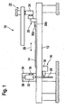
- FIG. 1 It carries a sawing machine as a whole the reference numeral 10. It comprises a horizontal support table 12, on which a workpiece 14, possibly also an entire stack of workpieces, can be stored.
- the sawing machine 10 further comprises a saw 16 with a saw carriage 18 and a Saw blade 20.
- the saw carriage 18 can be moved in a direction perpendicular to the sheet plane and perpendicular to the plane of the support table 12. In this way, the workpiece 14 can be sawn into sections.
- the sawing machine 10 In order to move the workpiece 14 to the saw 16, the sawing machine 10 also has a feed device 22. To this belongs a program pusher 24, which can be moved in the direction of the double arrow 26. At the program pusher 24 a plurality of collets 28 are mounted between the jaws 30a and 30b of the saw 16 remote edge of the workpiece 14 can be stretched.
- the saw blade 20 protrudes, as from FIG. 1 it can be seen, in the sawing of the saw carriage 18 slightly beyond the top of the support table 12 addition.
- the sawing machine 10 has a pressure bar 32. This is an elongate part perpendicular to the plane of the page FIG. 1 over the entire width of the support table 12 and thus over the entire length of the cutting line of the saw 16 extends.
- the pressure bar 32 is mounted vertically displaceably at its two ends on vertical supports. For illustration purposes is in FIG. 1 however, only the rear of the two vertical beams, which bears the reference numeral 34, is shown.
- the vertical displaceability of the pressure bar 32 is indicated by a double arrow 36, the linear guide of the pressure bar 32 in the carrier 34 is denoted by 38.
- the pressure bar 32 is lowered onto the workpiece 14, that is, the workpiece 14 is jammed between the pressure bar 32 and the support table 12.
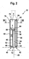
- the pressure bar is constructed in the present embodiment as a sheet metal construction. In one embodiment, not shown, it could be constructed of aluminum profiles. He includes a in FIG. 2 left housing part 40 and a right housing part 42.
- the left housing part 40 comprises an outer wall 44, which forms the inner wall of the housing part 40 in the upper region of the pressure bar 32.
- this has an inner wall 46, which is arranged at a distance D to the outer wall 44.
- outer wall 44 and inner wall 46 are interconnected by a horizontal sheet metal strip 48, at the top by an oblique sheet metal strip 50.
- the left housing 40 has a closed sheet metal box 52 with high torsional and bending stiffness.
- the right housing part 42 is constructed in the embodiment shown here as a rectangular metal box 54, with an outer wall 56, an inner wall 58 and the top and bottom connecting metal strips 60 and 62. From the left housing part 40 protrudes from the upper edge of the outer wall 44 is a horizontal to right housing part 42 extending metal strip 64 from. This is connected at its projecting end in a manner not shown with the right housing part 42. At its two end faces of the pressure bar 32 is closed by sheet metal panels 66 and 68 (see FIG. 3 ).
- FIG. 2 how out FIG. 2 it can be seen, the inner wall 46 of the left housing part 40 is spaced from the inner wall 58 of the right housing part 42. As a result, a sawing space 70 is formed between these two inner walls 46 and 58, the is open downwards or outwards via a kerf 72. In this way, during operation of the sawing machine 10, the saw blade 20 can engage in the sawing space 70, as in FIG FIG. 2 is shown by the dotted line indicated saw blade 20.
- the metal strip 50, the outer wall 44 of the left housing part 40, the metal strip 64, a portion of the inner wall 58 of the right housing part 42 and the metal strip 74 define a suction channel 76.
- the metal strip 74 forms insofar a partition between the saw chamber 70 and the suction 76th
- the suction channel 76 is connected via a suction opening 78, which is present in the metal strip 64, with a suction source, not shown.
- the suction source may be, for example, a suction pump.
- the partition wall 74 does not extend from the inner wall 58 of the right housing part 42 quite to the inner wall 46 of the left housing part 40, but ends at a distance therefrom.
- the projecting edge of the partition wall 74 limits so far a gap 80 which, as will be described in more detail below, forms a fluid connection between the saw chamber 70 and the suction channel 76 arranged directly above it.
- the projecting edge of the partition wall 74 is inclined, which causes the gap 80, starting from the suction opening 78, continuously, namely linearly expanded. Or, in other words, near the suction opening 78, the gap 80 has a smaller cross section than far away from the suction opening 78.
- the pressure bar 32 has a second suction channel 76 ', which adjoins the suction channel 76 in the longitudinal direction.
- Each of these suction channels 76 and 76 ' has its own outlet opening, wherein the outlet opening of the suction channel 76' is designated by 78 '.
- the suction channels 76 and 76 ' are separated by a partition wall 84.
- Each suction channel 76 and 76 ' has its own fluid connection formed for the suction channel 76' through the gap 80 'and bounded by the edge of a sheet metal strip 74'.
- a plurality of longitudinally successively arranged suction channels and fluid connections are present.
- the suction channels are individually switched on and off and / or the corresponding fluid connections selectively changed.
- the cross section of the fluid connection can be set in whole or in sections.
Landscapes
- Engineering & Computer Science (AREA)
- Mechanical Engineering (AREA)
- Sawing (AREA)
Claims (10)
- Barre de pression (32) pour une machine de sciage (10), comportant un espace de sciage (70), qui s'étend dans la direction longitudinale de la barre de pression (32) et qui s'ouvre vers l'extérieur par une fente de coupe (72), de telle sorte qu'en cours de service, une lame de scie (20) d'une scie (16) peut s'engager dans l'espace de sciage (70), comportant un conduit d'aspiration (76), qui est disposé parallèlement à l'espace de sciage (70) et communique avec ce dernier via une liaison fluidique, et comportant une ouverture d'aspiration (78, 78'), par l'intermédiaire de laquelle le conduit d'aspiration (76) peut être relié à une source d'aspiration, caractérisée en ce que la liaison fluidique (80, 80') entre le conduit d'aspiration (76) et l'espace de sciage (70) possède à proximité de l'ouverture d'aspiration (78, 78') une section transversale plus petite que celle éloignée de l'ouverture d'aspiration (78, 78').
- Barre de pression (32) selon la revendication 1, caractérisée en ce que la liaison fluidique comprend une fente (80, 80') allongée, qui s'étend parallèlement au conduit d'aspiration (76) et à l'espace de sciage (70).
- Barre de pression (32) selon la revendication 2, caractérisée en ce que la fente (80, 80') s'élargit en continu, en particulier linéairement, à partir de l'ouverture d'aspiration (78, 78').
- Barre de pression (32) selon la revendication 3, caractérisée en ce que le conduit d'aspiration (76) est disposé directement au-dessus de l'espace de sciage (70).
- Barre de pression (32) selon la revendication 4, caractérisée en ce que la fente (80, 80') est délimitée par le bord d'une cloison (74, 74') qui s'avance en saillie à partir d'une paroi de délimitation (58) sensiblement verticale et fait la séparation entre le conduit d'aspiration (76) et l'espace de sciage (70).
- Barre de pression (32) selon l'une quelconque des revendications précédentes, caractérisée en ce qu'elle comprend une construction en tôle ou est constituée de profilés en aluminium.
- Barre de pression (32) selon la revendication 6, caractérisée en ce qu'une cloison (74, 74'), dont le bord délimite une fente (80, 80') qui appartient à la liaison fluidique, est formée par un élément en tôle.
- Barre de pression (32) selon l'une quelconque des revendications précédentes, caractérisée en ce qu'elle comprend une pluralité de conduits d'aspiration (76, 76') séparés, disposés les uns derrière les autres.
- Barre de pression (32) selon la revendication 8, caractérisée en ce que les conduits d'aspiration (76, 76') peuvent être mis en service et hors service individuellement et/ou les liaisons fluidiques (80, 80') correspondantes peuvent être modifiées de manière ciblée.
- Barre de pression (32) selon l'une quelconque des revendications précédentes, caractérisée en ce que la section transversale de la liaison fluidique (80, 80') peut être réglée en totalité ou par zones.
Applications Claiming Priority (2)
| Application Number | Priority Date | Filing Date | Title |
|---|---|---|---|
| DE102006055446A DE102006055446A1 (de) | 2006-11-24 | 2006-11-24 | Druckbalken für eine Sägemaschine |
| PCT/EP2007/007365 WO2008061577A1 (fr) | 2006-11-24 | 2007-08-22 | Barre de pression pour une machine à scier |
Publications (2)
| Publication Number | Publication Date |
|---|---|
| EP2091683A1 EP2091683A1 (fr) | 2009-08-26 |
| EP2091683B1 true EP2091683B1 (fr) | 2011-11-16 |
Family
ID=38682636
Family Applications (1)
| Application Number | Title | Priority Date | Filing Date |
|---|---|---|---|
| EP07801798A Not-in-force EP2091683B1 (fr) | 2006-11-24 | 2007-08-22 | Barre de pression pour une machine à scier |
Country Status (4)
| Country | Link |
|---|---|
| EP (1) | EP2091683B1 (fr) |
| AT (1) | ATE533582T1 (fr) |
| DE (1) | DE102006055446A1 (fr) |
| WO (1) | WO2008061577A1 (fr) |
Cited By (1)
| Publication number | Priority date | Publication date | Assignee | Title |
|---|---|---|---|---|
| CN112222531A (zh) * | 2020-10-10 | 2021-01-15 | 江西邦展建筑模板科技有限公司 | 一种铝合金板材智能切割装置 |
Families Citing this family (2)
| Publication number | Priority date | Publication date | Assignee | Title |
|---|---|---|---|---|
| DE102012212391B4 (de) * | 2012-07-16 | 2026-04-02 | Frimo Group Gmbh | Bearbeitungsanordnung mit einer Aufnahme mit Absaugnut zur Werkstückbearbeitung |
| AT521555A1 (de) | 2018-07-26 | 2020-02-15 | Fill Gmbh | Plattensäge |
Family Cites Families (5)
| Publication number | Priority date | Publication date | Assignee | Title |
|---|---|---|---|---|
| CH96905A (de) * | 1920-03-09 | 1923-04-02 | Kuendig Arnold | Verfahren zum Absaugen von durch feste Bestandteile verunreinigter Luft bei mindestens einer Arbeitsmaschine und Vorrichtung zur Ausführung des Verfahrens. |
| IT1249228B (it) * | 1991-04-10 | 1995-02-21 | Giben Impianti Spa | Pressore bilaterale per sezionatrici. |
| DE4331283C1 (de) * | 1993-09-15 | 1994-10-20 | Holzma Maschinenbau Gmbh | Druckbalken für Plattenaufteilsägen |
| DE4433829C2 (de) * | 1994-09-22 | 1996-09-05 | Holzma Maschinenbau Gmbh | Druckbalken für Sägemaschinen |
| IT1305812B1 (it) * | 1996-05-20 | 2001-05-16 | Selco S R L Ora Selco S P A | Macchina sezionatrice con dispositivo di aspirazione di truciolie polvere |
-
2006
- 2006-11-24 DE DE102006055446A patent/DE102006055446A1/de not_active Ceased
-
2007
- 2007-08-22 WO PCT/EP2007/007365 patent/WO2008061577A1/fr not_active Ceased
- 2007-08-22 AT AT07801798T patent/ATE533582T1/de active
- 2007-08-22 EP EP07801798A patent/EP2091683B1/fr not_active Not-in-force
Cited By (1)
| Publication number | Priority date | Publication date | Assignee | Title |
|---|---|---|---|---|
| CN112222531A (zh) * | 2020-10-10 | 2021-01-15 | 江西邦展建筑模板科技有限公司 | 一种铝合金板材智能切割装置 |
Also Published As
| Publication number | Publication date |
|---|---|
| ATE533582T1 (de) | 2011-12-15 |
| WO2008061577A1 (fr) | 2008-05-29 |
| EP2091683A1 (fr) | 2009-08-26 |
| DE102006055446A1 (de) | 2008-05-29 |
Similar Documents
| Publication | Publication Date | Title |
|---|---|---|
| DE102007010207B4 (de) | Plattenaufteilanlage zum Aufteilen von plattenförmigen Werkstücken, sowie Verfahren zu deren Betrieb | |
| EP1842620B1 (fr) | Couvercle pour le guidage de machines-outils | |
| EP2127829A1 (fr) | Installation de distribution de plaques | |
| WO2008125326A2 (fr) | Dispositif de séparation d'un assemblage de tiges en matière plastique à l'aide d'un dispositif à entaille et d'un support portant un dispositif de découpe | |
| DE102009033649A1 (de) | Plattenaufteilanlage | |
| WO2014121866A1 (fr) | Installation de division de plaques destinée à diviser des pièces en forme de plaque | |
| DE102008058162B4 (de) | Sägemaschine | |
| DE3439739A1 (de) | Werkstueckauflagetisch fuer plattensaegen | |
| EP1636001B1 (fr) | Machine pour profiler des pieces plates allongees le long des aretes longitudinales | |
| EP3081325B1 (fr) | Installation de coupe de panneaux | |
| EP2091683B1 (fr) | Barre de pression pour une machine à scier | |
| EP2366512A1 (fr) | Dispositif de découpe de plaques | |
| AT506146B1 (de) | Sägemaschine | |
| DE102013206159A1 (de) | Plattenaufteilanlage | |
| EP2711116B1 (fr) | Poutre de pression pour un dispositif de sciage | |
| EP2022613B1 (fr) | Dispositif de poussée dans une installation de coupe de béton poreux | |
| EP4230369B1 (fr) | Installation de découpe de panneaux | |
| EP2193894B9 (fr) | Procédé de sciage d'au moins une plaque | |
| EP2236232B1 (fr) | Scie mécanique | |
| DE202004015554U1 (de) | Spaltmaschine | |
| EP2657169A1 (fr) | Dispositif de poches de pliage pour une plieuse à poches | |
| EP1958723B1 (fr) | Poutre de pression pour une installation de traitement de plaques | |
| DE4433829C2 (de) | Druckbalken für Sägemaschinen | |
| DE4306949C2 (de) | Vorrichtung zum Schneiden von im wesentlichen plattenförmigem Schneidgut | |
| DE29811070U1 (de) | Schneidmaschine |
Legal Events
| Date | Code | Title | Description |
|---|---|---|---|
| PUAI | Public reference made under article 153(3) epc to a published international application that has entered the european phase |
Free format text: ORIGINAL CODE: 0009012 |
|
| 17P | Request for examination filed |
Effective date: 20090411 |
|
| AK | Designated contracting states |
Kind code of ref document: A1 Designated state(s): AT BE BG CH CY CZ DE DK EE ES FI FR GB GR HU IE IS IT LI LT LU LV MC MT NL PL PT RO SE SI SK TR |
|
| DAX | Request for extension of the european patent (deleted) | ||
| GRAP | Despatch of communication of intention to grant a patent |
Free format text: ORIGINAL CODE: EPIDOSNIGR1 |
|
| GRAS | Grant fee paid |
Free format text: ORIGINAL CODE: EPIDOSNIGR3 |
|
| GRAA | (expected) grant |
Free format text: ORIGINAL CODE: 0009210 |
|
| AK | Designated contracting states |
Kind code of ref document: B1 Designated state(s): AT BE BG CH CY CZ DE DK EE ES FI FR GB GR HU IE IS IT LI LT LU LV MC MT NL PL PT RO SE SI SK TR |
|
| REG | Reference to a national code |
Ref country code: GB Ref legal event code: FG4D Free format text: NOT ENGLISH |
|
| REG | Reference to a national code |
Ref country code: CH Ref legal event code: EP |
|
| REG | Reference to a national code |
Ref country code: IE Ref legal event code: FG4D Free format text: LANGUAGE OF EP DOCUMENT: GERMAN |
|
| REG | Reference to a national code |
Ref country code: DE Ref legal event code: R096 Ref document number: 502007008698 Country of ref document: DE Effective date: 20120126 |
|
| REG | Reference to a national code |
Ref country code: NL Ref legal event code: VDEP Effective date: 20111116 |
|
| LTIE | Lt: invalidation of european patent or patent extension |
Effective date: 20111116 |
|
| PG25 | Lapsed in a contracting state [announced via postgrant information from national office to epo] |
Ref country code: IS Free format text: LAPSE BECAUSE OF FAILURE TO SUBMIT A TRANSLATION OF THE DESCRIPTION OR TO PAY THE FEE WITHIN THE PRESCRIBED TIME-LIMIT Effective date: 20120316 Ref country code: LT Free format text: LAPSE BECAUSE OF FAILURE TO SUBMIT A TRANSLATION OF THE DESCRIPTION OR TO PAY THE FEE WITHIN THE PRESCRIBED TIME-LIMIT Effective date: 20111116 |
|
| PG25 | Lapsed in a contracting state [announced via postgrant information from national office to epo] |
Ref country code: LV Free format text: LAPSE BECAUSE OF FAILURE TO SUBMIT A TRANSLATION OF THE DESCRIPTION OR TO PAY THE FEE WITHIN THE PRESCRIBED TIME-LIMIT Effective date: 20111116 Ref country code: NL Free format text: LAPSE BECAUSE OF FAILURE TO SUBMIT A TRANSLATION OF THE DESCRIPTION OR TO PAY THE FEE WITHIN THE PRESCRIBED TIME-LIMIT Effective date: 20111116 Ref country code: PT Free format text: LAPSE BECAUSE OF FAILURE TO SUBMIT A TRANSLATION OF THE DESCRIPTION OR TO PAY THE FEE WITHIN THE PRESCRIBED TIME-LIMIT Effective date: 20120316 Ref country code: SE Free format text: LAPSE BECAUSE OF FAILURE TO SUBMIT A TRANSLATION OF THE DESCRIPTION OR TO PAY THE FEE WITHIN THE PRESCRIBED TIME-LIMIT Effective date: 20111116 Ref country code: SI Free format text: LAPSE BECAUSE OF FAILURE TO SUBMIT A TRANSLATION OF THE DESCRIPTION OR TO PAY THE FEE WITHIN THE PRESCRIBED TIME-LIMIT Effective date: 20111116 Ref country code: PL Free format text: LAPSE BECAUSE OF FAILURE TO SUBMIT A TRANSLATION OF THE DESCRIPTION OR TO PAY THE FEE WITHIN THE PRESCRIBED TIME-LIMIT Effective date: 20111116 Ref country code: GR Free format text: LAPSE BECAUSE OF FAILURE TO SUBMIT A TRANSLATION OF THE DESCRIPTION OR TO PAY THE FEE WITHIN THE PRESCRIBED TIME-LIMIT Effective date: 20120217 |
|
| REG | Reference to a national code |
Ref country code: IE Ref legal event code: FD4D |
|
| PG25 | Lapsed in a contracting state [announced via postgrant information from national office to epo] |
Ref country code: CY Free format text: LAPSE BECAUSE OF FAILURE TO SUBMIT A TRANSLATION OF THE DESCRIPTION OR TO PAY THE FEE WITHIN THE PRESCRIBED TIME-LIMIT Effective date: 20111116 |
|
| PG25 | Lapsed in a contracting state [announced via postgrant information from national office to epo] |
Ref country code: BG Free format text: LAPSE BECAUSE OF FAILURE TO SUBMIT A TRANSLATION OF THE DESCRIPTION OR TO PAY THE FEE WITHIN THE PRESCRIBED TIME-LIMIT Effective date: 20120216 Ref country code: SK Free format text: LAPSE BECAUSE OF FAILURE TO SUBMIT A TRANSLATION OF THE DESCRIPTION OR TO PAY THE FEE WITHIN THE PRESCRIBED TIME-LIMIT Effective date: 20111116 Ref country code: EE Free format text: LAPSE BECAUSE OF FAILURE TO SUBMIT A TRANSLATION OF THE DESCRIPTION OR TO PAY THE FEE WITHIN THE PRESCRIBED TIME-LIMIT Effective date: 20111116 Ref country code: DK Free format text: LAPSE BECAUSE OF FAILURE TO SUBMIT A TRANSLATION OF THE DESCRIPTION OR TO PAY THE FEE WITHIN THE PRESCRIBED TIME-LIMIT Effective date: 20111116 Ref country code: CZ Free format text: LAPSE BECAUSE OF FAILURE TO SUBMIT A TRANSLATION OF THE DESCRIPTION OR TO PAY THE FEE WITHIN THE PRESCRIBED TIME-LIMIT Effective date: 20111116 Ref country code: IE Free format text: LAPSE BECAUSE OF FAILURE TO SUBMIT A TRANSLATION OF THE DESCRIPTION OR TO PAY THE FEE WITHIN THE PRESCRIBED TIME-LIMIT Effective date: 20111116 |
|
| PG25 | Lapsed in a contracting state [announced via postgrant information from national office to epo] |
Ref country code: IT Free format text: LAPSE BECAUSE OF FAILURE TO SUBMIT A TRANSLATION OF THE DESCRIPTION OR TO PAY THE FEE WITHIN THE PRESCRIBED TIME-LIMIT Effective date: 20111116 Ref country code: RO Free format text: LAPSE BECAUSE OF FAILURE TO SUBMIT A TRANSLATION OF THE DESCRIPTION OR TO PAY THE FEE WITHIN THE PRESCRIBED TIME-LIMIT Effective date: 20111116 |
|
| PLBE | No opposition filed within time limit |
Free format text: ORIGINAL CODE: 0009261 |
|
| STAA | Information on the status of an ep patent application or granted ep patent |
Free format text: STATUS: NO OPPOSITION FILED WITHIN TIME LIMIT |
|
| 26N | No opposition filed |
Effective date: 20120817 |
|
| REG | Reference to a national code |
Ref country code: DE Ref legal event code: R097 Ref document number: 502007008698 Country of ref document: DE Effective date: 20120817 |
|
| BERE | Be: lapsed |
Owner name: HOLZMA PLATTENAUFTEILTECHNIK G.M.B.H. Effective date: 20120831 |
|
| REG | Reference to a national code |
Ref country code: CH Ref legal event code: PL |
|
| PG25 | Lapsed in a contracting state [announced via postgrant information from national office to epo] |
Ref country code: MC Free format text: LAPSE BECAUSE OF NON-PAYMENT OF DUE FEES Effective date: 20120831 |
|
| GBPC | Gb: european patent ceased through non-payment of renewal fee |
Effective date: 20120822 |
|
| PG25 | Lapsed in a contracting state [announced via postgrant information from national office to epo] |
Ref country code: CH Free format text: LAPSE BECAUSE OF NON-PAYMENT OF DUE FEES Effective date: 20120831 Ref country code: LI Free format text: LAPSE BECAUSE OF NON-PAYMENT OF DUE FEES Effective date: 20120831 Ref country code: ES Free format text: LAPSE BECAUSE OF FAILURE TO SUBMIT A TRANSLATION OF THE DESCRIPTION OR TO PAY THE FEE WITHIN THE PRESCRIBED TIME-LIMIT Effective date: 20120227 |
|
| REG | Reference to a national code |
Ref country code: FR Ref legal event code: ST Effective date: 20130430 |
|
| PG25 | Lapsed in a contracting state [announced via postgrant information from national office to epo] |
Ref country code: BE Free format text: LAPSE BECAUSE OF NON-PAYMENT OF DUE FEES Effective date: 20120831 |
|
| PG25 | Lapsed in a contracting state [announced via postgrant information from national office to epo] |
Ref country code: FI Free format text: LAPSE BECAUSE OF FAILURE TO SUBMIT A TRANSLATION OF THE DESCRIPTION OR TO PAY THE FEE WITHIN THE PRESCRIBED TIME-LIMIT Effective date: 20111116 |
|
| PG25 | Lapsed in a contracting state [announced via postgrant information from national office to epo] |
Ref country code: GB Free format text: LAPSE BECAUSE OF NON-PAYMENT OF DUE FEES Effective date: 20120822 |
|
| PG25 | Lapsed in a contracting state [announced via postgrant information from national office to epo] |
Ref country code: FR Free format text: LAPSE BECAUSE OF NON-PAYMENT OF DUE FEES Effective date: 20120831 |
|
| REG | Reference to a national code |
Ref country code: AT Ref legal event code: MM01 Ref document number: 533582 Country of ref document: AT Kind code of ref document: T Effective date: 20120831 |
|
| PG25 | Lapsed in a contracting state [announced via postgrant information from national office to epo] |
Ref country code: AT Free format text: LAPSE BECAUSE OF NON-PAYMENT OF DUE FEES Effective date: 20120831 |
|
| PG25 | Lapsed in a contracting state [announced via postgrant information from national office to epo] |
Ref country code: MT Free format text: LAPSE BECAUSE OF FAILURE TO SUBMIT A TRANSLATION OF THE DESCRIPTION OR TO PAY THE FEE WITHIN THE PRESCRIBED TIME-LIMIT Effective date: 20111116 |
|
| PG25 | Lapsed in a contracting state [announced via postgrant information from national office to epo] |
Ref country code: TR Free format text: LAPSE BECAUSE OF FAILURE TO SUBMIT A TRANSLATION OF THE DESCRIPTION OR TO PAY THE FEE WITHIN THE PRESCRIBED TIME-LIMIT Effective date: 20111116 |
|
| PG25 | Lapsed in a contracting state [announced via postgrant information from national office to epo] |
Ref country code: LU Free format text: LAPSE BECAUSE OF NON-PAYMENT OF DUE FEES Effective date: 20120822 |
|
| PG25 | Lapsed in a contracting state [announced via postgrant information from national office to epo] |
Ref country code: HU Free format text: LAPSE BECAUSE OF FAILURE TO SUBMIT A TRANSLATION OF THE DESCRIPTION OR TO PAY THE FEE WITHIN THE PRESCRIBED TIME-LIMIT Effective date: 20070822 |
|
| PGFP | Annual fee paid to national office [announced via postgrant information from national office to epo] |
Ref country code: DE Payment date: 20151019 Year of fee payment: 9 |
|
| REG | Reference to a national code |
Ref country code: DE Ref legal event code: R119 Ref document number: 502007008698 Country of ref document: DE |
|
| PG25 | Lapsed in a contracting state [announced via postgrant information from national office to epo] |
Ref country code: DE Free format text: LAPSE BECAUSE OF NON-PAYMENT OF DUE FEES Effective date: 20170301 |