EP2091689B1 - Vorrichtung zur bestimmung der position und/oder der querabmessung eines bohrlochs in einer linse zur herstellung von brillen mit randlosem rahmen - Google Patents
Vorrichtung zur bestimmung der position und/oder der querabmessung eines bohrlochs in einer linse zur herstellung von brillen mit randlosem rahmen Download PDFInfo
- Publication number
- EP2091689B1 EP2091689B1 EP07872397A EP07872397A EP2091689B1 EP 2091689 B1 EP2091689 B1 EP 2091689B1 EP 07872397 A EP07872397 A EP 07872397A EP 07872397 A EP07872397 A EP 07872397A EP 2091689 B1 EP2091689 B1 EP 2091689B1
- Authority
- EP
- European Patent Office
- Prior art keywords
- image
- drill hole
- lens
- center
- transverse dimension
- Prior art date
- Legal status (The legal status is an assumption and is not a legal conclusion. Google has not performed a legal analysis and makes no representation as to the accuracy of the status listed.)
- Active
Links
Images

Classifications
-
- B—PERFORMING OPERATIONS; TRANSPORTING
- B24—GRINDING; POLISHING
- B24B—MACHINES, DEVICES, OR PROCESSES FOR GRINDING OR POLISHING; DRESSING OR CONDITIONING OF ABRADING SURFACES; FEEDING OF GRINDING, POLISHING, OR LAPPING AGENTS
- B24B9/00—Machines or devices designed for grinding edges or bevels on work or for removing burrs; Accessories therefor
- B24B9/02—Machines or devices designed for grinding edges or bevels on work or for removing burrs; Accessories therefor characterised by a special design with respect to properties of materials specific to articles to be ground
- B24B9/06—Machines or devices designed for grinding edges or bevels on work or for removing burrs; Accessories therefor characterised by a special design with respect to properties of materials specific to articles to be ground of non-metallic inorganic material, e.g. stone, ceramics, porcelain
- B24B9/08—Machines or devices designed for grinding edges or bevels on work or for removing burrs; Accessories therefor characterised by a special design with respect to properties of materials specific to articles to be ground of non-metallic inorganic material, e.g. stone, ceramics, porcelain of glass
- B24B9/14—Machines or devices designed for grinding edges or bevels on work or for removing burrs; Accessories therefor characterised by a special design with respect to properties of materials specific to articles to be ground of non-metallic inorganic material, e.g. stone, ceramics, porcelain of glass of optical work, e.g. lenses, prisms
- B24B9/146—Accessories, e.g. lens mounting devices
-
- B—PERFORMING OPERATIONS; TRANSPORTING
- B24—GRINDING; POLISHING
- B24B—MACHINES, DEVICES, OR PROCESSES FOR GRINDING OR POLISHING; DRESSING OR CONDITIONING OF ABRADING SURFACES; FEEDING OF GRINDING, POLISHING, OR LAPPING AGENTS
- B24B13/00—Machines or devices designed for grinding or polishing optical surfaces on lenses or surfaces of similar shape on other work; Accessories therefor
- B24B13/005—Blocking means, chucks or the like; Alignment devices
- B24B13/0055—Positioning of lenses; Marking of lenses
Definitions
- the present invention generally relates to the mounting of ophthalmic lenses of a pair of spectacles on a mount of the type without a circle and more particularly to a device for determining the position and / or a transverse dimension of a drilling hole.
- a presentation lens serving as a model for drilling, at said position and / or at said transverse dimension, a mounting lens that is to be assembled to a spectacle frame of the type without a circle.
- the following drilling method is implemented.
- the frame equipped with presentation lenses, that he wishes.
- the optician places the presentation lenses one after the other in a device for determining the position of the drilling holes.
- Each presentation lens is already pierced on its temporal and nasal parts and then serves as a model for the trimming and proper drilling of the corresponding left or right correction lens intended to equip the future wearer with the mount he has chosen.
- the presentation lens is thus placed in a support between projected vision lighting means and image capture means, the front face of the lens being directed towards the lighting means.
- a frosted glass plate makes it possible to form the image of the shadow of the lens, in projected vision, on the capture means.
- the image of the shadow of the presentation lens is acquired.
- This overall image is displayed on a screen.
- a virtual registration ring that the operator visualizes and moves on the screen to superimpose, sizing and centering on the overall image of the drilling hole of the presentation lens.
- the operator validates this positioning and this dimensioning and the processing system stores the position of the center and the transverse dimension (ie its diameter if the hole is round) of the registration ring as being the position of the center and the transverse dimension of the drilling hole to be made on the correction lens.
- a drill bit having a suitable diameter is brought, vis-à-vis the correction lens, to the stored position of the hole to be drilled.
- the correction lens is then pierced by means of a relative advance movement of the drill bit relative to the lens along the axis of rotation of the drill bit. If the diameter of the drill bit is smaller than the desired diameter, the hole obtained is widened to the right diameter by means of a suitable transverse displacement of the drill bit.
- the object of the present invention is to determine accurately the position and / or a transverse dimension of a drilling hole to be made on a lens that is to be assembled to a bezel mount of the type without a circle.
- the drill pierces the corrective lens at a point on the face of the lens which becomes the center of the front mouth of the drilling hole in progress of realization.
- the drill is brought opposite the front face of the lens to the position associated with the center of the overall figure of the drilling hole of the presentation lens which corresponds generally to the position of the center of the overall image drilling hole of the presentation lens projected on a plane perpendicular to the direction of illumination or image capture.
- the position of the center of the mouth of the piercing hole opening on one of the faces of the lens is calculated from the acquired overall image. as well as its transverse dimension, which then makes it possible to correctly position the drill opposite this determined position of the center of the mouth on the front face and / or to size and control this drill to obtain a hole whose transverse dimension corresponds precisely to to that of the hole of the presentation lens.
- the drilling hole obtained on the corrective lens is then correctly positioned and / or dimensioned.
- said first correction means operate further according to the index and / or the thickness of the presentation lens. This corrects the image capture errors resulting from the prismatic deviations generated by the presentation lens on its own image.
- said means for defining the position of the center of the mouth of the drilling hole opening on said face operate a calculation of the first correction as a function of the index and / or the thickness of the presentation lens. This corrects the image capture errors resulting from the prismatic deviations generated by the presentation lens on its own images.
- said first correction means operate further depending on the index and / or the thickness of the presentation lens. This corrects the image capture errors resulting from the prismatic deviations generated by the presentation lens on its own image.
- the processing means are able to determine, from said overall image of the drilling hole, a relative distance in projection, between the center of said mouth of the drilling hole of the presentation lens and the edge of the presentation lens, projected in said direction of illumination or image capture in an acquisition plane substantially perpendicular to said direction d lighting or image capture.
- the processing means comprise second correction means capable of calculating, from this relative distance in projection and as a function of at least one datum representative of the angle of inclination of the drilling hole formed between the direction for illuminating or capturing images and the axis of the drilling hole, a real relative distance between the center of said mouth and the edge of the presentation lens, considered in the plane perpendicular to the axis of the drilling hole .
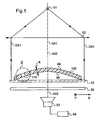
- FIG. 1 there is shown a device for acquiring the position of the drilling holes of a spectacle lens.
- This acquisition device comprises lighting means 51, 52, a support 55 of the presentation lens 100 and capture means 53 of an image.
- the lighting means 51, 52 comprise a collimation lens 52 of axis A52 and a light source 51 placed at the focus of the collimation lens 52. After passing through the collimation lens 52, the light rays are thus directed in parallel. to the axis A52 of the collimation lens 52.
- the illumination direction D51 is thus parallel to the direction of the axis A52.
- the capture means 53 comprise a camera 53 provided with a lens having an optical axis A53.
- the device for acquiring the position of the drilling holes comprises an optical axis defined as the axis A52 of the collimation lens 52 and the axis A53 of the objective of the acquisition means 53. image by the acquisition means 53 is confused with the direction of illumination. D51.
- the support 55 of the presentation lens 100 is designed such that the presentation lens 100 extends in the plane transverse to the direction of illumination D51. The lens 100 is then illuminated in front.
- the support 55 of the lens 100 is here in the form of a transparent glass plate perpendicular to the direction of illumination D51, so that neither the front face 98 nor the rear face 99 are visually masked by the support 55 .
- This presentation lens 100 has two piercing holes, a first piercing hole 110 located on the side of the temporal area and another piercing hole (not shown) located on the side of the nasal area of the lens.
- the following description only details the acquisition of the drilling hole 110, but this description also applies to the acquisition of the other drilling hole.
- the drilling hole 110 comprises, on the one hand, a mouthpiece 111 which opens on the front face 98 of the lens 100 and, secondly, a mouth 112 which opens on the rear face 99 of the lens 100. It also defines the center C2 of the drilling hole 110 itself which is also the average of the positions of the centers C1, C3 of the front mouthpieces 111 and rear 112.
- the image capture means 53 are also connected with processing means 54 of this image.
- the processing means 54 of this image are designed to deduce from the acquired image the position of the center C1 of the mouth 111 of the drilling hole 110 in the front face 98.
- the processing means 54 may also be designed to deduce from the acquired image, the position of the center of the mouth 112 of the drilling hole 110 on the rear face 99.
- the drilling hole position acquisition device is designed such that the camera 53 sees the lens in projected vision.
- the lighting means 51, 52 and the camera 53 are distributed on either side of the support of the lens.
- the frosted glass plate 50 is centered on the axis A52 of the collimating lens 52 and extends in the plane transverse to this axis A52.
- the frosted glass plate 50 makes it possible to form the shadow of the lens 100 and in particular the shadow of the drilling hole 110 of the lens.
- the image of the shadow of the drilling hole 110 of the lens is acquired by the acquisition device 53.
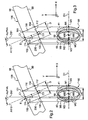
- This image represented on the lower part of the figure 2 shows an overall figure 90 of the drilling hole.
- the overall figure 90 of the piercing hole comprises two rings 40, 41 of substantially oval shape which intersect each other.
- the first ring 40 is the projected shadow of the mouthpiece 111 on the front face of the drilling hole 110
- the second ring 41 is the projected shadow of the mouth 112 on the rear face.
- the portion constituted by the superposition of the two rings 40, 41 is clear. Indeed, this portion is the result of the projection of a portion of the piercing hole which is traversed by the light rays without meeting the material of the lens. Conversely, the non-superposed portions of the two rings are dark due to the reflection or diffusion of these rays by the side wall of the drilling hole.
- the point 102 of the drilling hole 110 results from the intersection between, on the one hand, a cutting plane of the lens passing through an axis parallel to the illumination direction D51 and the axis A110 of the drilling hole 110 and on the other hand, the part of the contour of the mouth 111 in the front face 98 of the lens, located towards the outside of the lens.
- point 101 is defined as the point of intersection of the cutting plane of the lens with the portion of the contour of the mouth 111 of the front face 98 of the lens, located towards the inside of the lens.
- the points 105 and 104 are defined as the points of intersection of the cutting plane of the lens with the portion of the mouth 99 on the rear face 99 of the lens, located respectively outwardly and inwardly of the lens. lens.
- a line D1 which is the straight line passing through the center of the two rings 40, 41.
- This line D1 corresponds approximately to the trace on the screen 50 of the plane passing through the axis A52 of the lens 100 and the center C2 of hole 110.
- the points M1 and M2 are the points of intersection of the straight line D1 with respectively the right and left parts of the ring 40 as shown in FIG. Figure 2B . These points M1 and M2 are the image points of the points 101 and 102. Similarly, the points M4 and M5 are the points of intersection of the line D1 with respectively the right and left parts of the second ring 41 as represented on FIG. Figure 2B . These points M4 and M5 are the image points of the points 104 and 105.
- XM1, XM2, XM4, XM5 denote the positions of the points M1, M2, M4, M5 on the line D1.
- the point MC1 is the image point on the line D1 of the center C1, in projection in the image capture plane, whose position XMC1 is to be calculated. Once the position XMC1 of the center C1 is determined we calculate its distance from a reference point of the edge of the lens.
- a first method of execution of the main embodiment illustrated by the figure 2 , it is intended to determine the position XM90 of the center M90 of the overall figure 90 of the drilling hole and to deduce the position of the center C1 of the mouthpiece 111 on the front face 98 of this drilling hole 110.
- the processing system 54 includes a user interface and a display screen (not shown) which displays the overall image 90 of the drilling hole 110.
- the processing system 54 is also designed to allow display on the display. 60.
- This ring has dimensions that can be modified by the operator.
- the treatment system 54 is also designed such that this locating ring 60 is movable by the operator on the display screen. The displacement of the registration ring 60 as well as the adjustments of its dimensions can be obtained using control tools integrated in the user interface of the processing system 54.
- the operator sizes and centers the registration ring 60 on the overall image 90 of the drilling hole 110.
- the operator can, by example as illustrated by the figure 2 , superimpose the registration ring 60 in the overall figure 90 so that the locating ring 60 passes through the middle of the segments M1 M4 and M2M5.
- the optician may alternatively provide for adjusting the position and the dimension of the registration ring 60 to make it pass through the points M1 and M5 bordering the clear part of the overall figure 90. It can further adjust the position and the dimension of the registration ring 60 to make it pass through the points M2 and M4 bordering the dark part of the overall figure 90.
- the processing system 54 automatically detects and stores the position of the center M60 of the registration ring 60.
- the position of the center M60 is associated by the processing means 54 at the XM90 position of the center M90 of the overall figure 90.
- the operator points on the screen, with a tool integrated in the user interface such as a mouse or a stylus, the center M60 of the registration ring 60 which is then stored:
- the processing system 54 calculates the position of the center C1 of the mouth of the drilling hole 110 opening on said face from the position of the center M90 of said overall figure 90 and as a function of the angle of inclination ALPHA the drilling hole 110 and the thickness E of the lens.
- the angle of inclination ALPHA is the angle formed between the average direction of illumination D51 and the axis A110 of the drilling hole.
- the angle ALPHA and the thickness E of the lens can be measured by probing the lens, for example, or manually entered by the operator using an on-screen input interface provided for this purpose. .
- the considered thickness of the lens may be the local thickness of the lens around the piercing hole or the average thickness of the lens.
- XMC ⁇ 1 XM ⁇ 90 - E / 2. ⁇ sin ALPHA .
- the processing system 54 then associates said calculated position with the desired position of the center C1 of the mouth of the drilling hole 110 opening on the front face 98 of the lens 100.
- XMC ⁇ 3 XM ⁇ 90 + E / 2. ⁇ sin ALPHA .
- the calculation of the value of the diameter D of the hole 110 depends on the method of superposition of the registration ring 60 in the overall figure 90 used.
- the detection of the center M60 of the registration ring 60 is performed automatically by the processing system 54, which is then designed to superimpose (with proper centering and sizing) automatically the register ring 60 on the overall image 90 of the drilling hole 110 and thus deduce the position and the diameter of the center M60 of this ring.
- the figure 3 of the first method it is planned to improve the accuracy of the calculation of the position XMC1 of the projection MC1 of the center C1, from the position XM90 of the center M90 of the overall figure 90, taking into account the prismatic deviations induced by the presentation lens 100 and therefore the index of this lens.
- the index of the presentation lens is then different from 1, and is worth, for example, 1.5.
- the accuracy of the calculation of the diameter D of the hole in taking into account the index of this lens depends on the method of superposition of the registration ring 60 in the overall figure 90 used.
- the position of the center of the overall figure of the drilling hole is not determined, but the positions of points M1 and M2 are acquired.
- the points M1, M2, as recalled above, are the intersections of the line D1 with the right and left parts of the ring 40.
- the acquisition of the positions of the points M1 and M2 can be performed by an algorithm for automatically detecting the position of these points.
- This algorithm can be designed so as to take, on the one hand, the leftmost position of the darkest point of the overall figure 90 to obtain the position XM2 of the point M2 and, on the other hand, the position of the rightmost point of the clear portion of the overall figure 90 to obtain the position XM1 of the point M1. It is also possible, alternatively, that the overall figure is displayed on a screen and that the operator points on the screen the positions of the points M1 and M2.
- the center X12 of the segment M1, M2 is then determined.
- the processing means 54 then associate the position of the center X12 of the segment M1, M2 to the position XMC1 of the center C1 of the mouth of the drilling hole 110 opening on the front face. It is understood that, in this example, the offset of the point M2 due to the prismatic effects of the lens 110 is not taken into account, which is an approximation.
- the second method it is planned to improve the accuracy of the calculation of the position XMC1 of the center C1, from the position of the points M1 and M2 of the figure 90, as well as the precision of the calculation of the diameter D of the hole 110, taking into account the index n of the presentation lens 100.
- the points M1, M4 and M5 were not shifted during the projection of the points 101, 104 and 105 in the image capture plane, the rays emerging from these points having not been deviated by the lens of
- a ray passes through point 102, it then passes through the lens and is then deviated by a certain distance which depends on the angle ALPHA, the index n of the lens and the the average thickness E of the lens.
- the ray ends at the point M2. So, as represented on the figure 3 , the projected distance on the line D1 between the point 102 and the point 105 is actually equal to the distance between a point M3 and the point M5.
- the position of the point M3 corresponds to the theoretical position of the projection on the line D1 of the point 102 along the optical axis of the optical device, without prismatic deflection by the presentation lens 100.
- the position X13 of the center of the segment defined by the two points M1, M3 corresponds to the corrected position, in view of the prismatic deviations, from the center C1 of the mouthpiece 111 of the drilling hole 110.
- XMC ⁇ 1 XMC ⁇ 3 - E . sin ALPHA .
- D abs ⁇ XM ⁇ 4 - XM ⁇ 5 / cos ALPHA
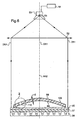
- the presentation lens 100 is seen by the camera 53 in direct vision.
- the camera 53 is arranged in such a way that the optical axis of its objective is parallel with the direction of illumination and that the optical center of its lens is located at the focus 51 of the collimation lens 52.
- a backlight assembly consisting of a matrix of light sources such as LEDs 56 and a plate of diffusion 57, is disposed on the side of the support plate 55 opposite to the lens 100.
- the camera 53 then sees directly, that is to say without intermediate projection screen, the presentation lens 100 on the front face.
- the lens of the camera acquires the image of the lens.
- the overall image of the piercing hole that the lens is acquired is schematically represented on the figure 7 .
- the ring 41 resulting from the projection view of the rear mouth of the drilling hole, flattens due to the optical deviation of the light rays from the portions of the contour of the mouth on the rear face located on the inner side of the hole.
- the lens
- This deformation can be corrected in a manner similar to that described above. But it is more convenient to directly read the diameter D40 of the ring 40 and to apply to it the geometric projection correction under the angle ALPHA.
- XMC3 XM ⁇ 2 + XM ⁇ 1 / 2 + abs ⁇ XM ⁇ 5 - XM ⁇ 2
- it is intended to further improve the accuracy of the calculation of the position of the center of the mouth of the front face of the drilling hole by taking into account at least one characteristic of corrective lens to pierce.
- This embodiment can also be applied to the rear face.
- the position of the center of the mouthpiece on the front face of the drilling hole is calculated according to one of the preceding embodiments which takes into account, in the calculation of the position of the drilling hole, the angle ALPHA formed between the mean direction D51 and the A110 axis of the drilling hole.
- the angle formed between an axis of the corrective lens and the normal to the face of the corrective lens is also acquired at the determined position of the drilling hole to be produced. Then the position of the drilling hole to be made on the corrective lens is corrected according to the difference in value between said angle and the angle ALPHA between the average illumination direction D51 and the axis A110 of the drilling hole.
- the measurement of this distance along the surface of the lens is carried out, in a manner known per se, from the position of the center of the mouth of the drilling hole determined according to one of the embodiments described above, of the XMB position of the reference point of the edge of the lens in the image plane and from the value of the base of the lens.
- R is the distance, projected on the line D1, from the center C1 to the geometric center of the contour of the lens (obtained by image processing), B being the base of the lens, and n being the index of the lens.
- the base of the lens can be entered manually by the operator using an on-screen input interface, or obtained, for example, by a spherometer.
- the angle ALPHA can also be calculated from the positions XM1 and XM4 of the points M1 and M4 with the following equation, in the measurement configuration previously defined in projected vision ( Figures 3 to 5 ):
- the thickness E of the lens can be measured for example by probing or be fixed at an average value of about 2 millimeters.
Landscapes
- Engineering & Computer Science (AREA)
- Mechanical Engineering (AREA)
- Chemical & Material Sciences (AREA)
- Ceramic Engineering (AREA)
- Inorganic Chemistry (AREA)
- Perforating, Stamping-Out Or Severing By Means Other Than Cutting (AREA)
- Drilling And Boring (AREA)
- Eyeglasses (AREA)
- Non-Portable Lighting Devices Or Systems Thereof (AREA)
Claims (12)
- Vorrichtung zum Bestimmen der Position und/oder eines Quermaßes (D) für ein Bohrloch (110) in einer Probierlinse (100) für eine fassungslose Brille, mit:- Haltemitteln (55) für die Linse (100),- Erfassungsmitteln (53) eines Gesamtbilds (90) des Bohrloches (110) in der Linse (100) entlang einer Beleuchtungs- (D51, A52) oder Bilderfassungsrichtung (A53),- Verarbeitungsmitteln (54) für das Bild, wenn die Linse von den Haltemitteln (55) getragen wird,dadurch gekennzeichnet, dass die Verarbeitungsmittel (54) anhand des Gesamtbilds des Bohrloches (110) die Position des Mittelpunkts (C1) der Mündung des Bohrloches (110) ermitteln können, das in eine der Seiten (98) der Linse (100) einmündet und/oder das Quermaß der Mündung des Bohrloches (110), das dem gesuchten Quermaß (D) entspricht.
- Vorrichtung nach Anspruch 1, in der die Verarbeitungsmittel (54) umfassen:- Mittel zum Aquirieren der Position des Mittelpunkts (M90) des Gesamtbildes (90) des Bohrloches (110) und- Mittel zur ersten Korrektur, die die Position des Mittelpunkts (C1) der Mündung des Bohrloches (110) auf dieser Seite anhand der Position des Mittelpunkts (M90) des Gesamtbildes (90) und in Abhängigkeit von mindestens einer repräsentativen Dateninformation über den Neigungswinkel (ALPHA) des Bohrloches (110), der zwischen der Beleuchtungs- (D51, A52) oder Bilderfassungsrichtung (A53) und der Achse (A110) des Bohrloches (110) gebildet wird, berechnen können.
- Vorrichtung nach vorausgehendem Anspruch, in der das Gesamtbild (90) mit einem ersten und einem zweiten Bilderring (40,41), die aus Bildern der Mündungen (111, 112) des Bohrloches (110) auf den Erfassungsmitteln (53) entstehen und teilweise überlappt sind, wobei die Mittel zum Aquirieren umfassen:- Mittel zum Erzeugen eines Markierungsrings (60)- Mittel zum Überlappen dieses Markierungsrings (60) mit dem Gesamtbild (90),- Mittel zum Speichern der Position des Mittelpunkts (M60) dieses Markierungsrings (60) und- Assoziationsmittel für die gespeicherte Position des Mittelpunkts (M60) dieses Markierungsrings (60) mit der Position des Mittelpunkts (M90) des Gesamtbildes (90) des Bohrloches (110).
- Vorrichtung nach einem der vorausgehenden Ansprüche, in der die Verarbeitungsmittel (54) umfassen:- Mittel zum Aquirieren des Quermaßes (DA) des erfassten Gesamtbildes (90) des Bohrloches (110) und- Mittel zur ersten Korrektur, die das Quermaß (D) der Mündung des Bohrloches (110) auf dieser Seite anhand des Quermaßes (DA) des Gesamtbildes (90) und in Abhängigkeit von mindestens einer repräsentativen Dateninformation über den Neigungswinkel (ALPHA) des Bohrloches (110) zwischen der Beleuchtungs- (D51, A52) oder der Bilderfassungsrichtung (A53) und der Achse (A110) des Bohrloches (110) berechnen können.
- Vorrichtung nach vorausgehendem Anspruch, in der das Gesamtbild (90) mit einem ersten und einem zweiten Bilderring (40, 41), die aus Bildern der Mündungen (111, 112) des Bohrloches (110) auf den Erfassungsmitteln (53) entstehen und teilweise überlappt sind, wobei die Mittel zum Aquirieren umfassen:- Mittel zum Erzeugen eines Markierungsrings (60)- Mittel zum Überlappen und zur Dimensionierung dieses Markierungsrings (60) mit dem Gesamtbild (90),- Mittel zum Speichern des Quermaßes (DA) dieses Markierungsrings (60) und- Assoziationsmittel für das gespeicherte Quermaß (DA) dieses Markierungsrings (60) mit dem Quermaß (DA) des Gesamtbildes (90) des Bohrloches (110).
- Vorrichtung nach einem der Ansprüche 2 bis 5, in der die Mittel zur ersten Korrektur zudem in Abhängigkeit des Indexes (n) und/oder der Stärke (E) der Probierlinse (100) arbeiten.
- Vorrichtung nach Anspruch 1, in der das Gesamtbild (90) mit einem ersten und einem zweiten Bilderring (40,41), die aus Bildern der Mündungen (111, 112) des Bohrloches (110) auf den Erfassungsmitteln (53) entstehen und teilweise überlappt sind, wobei die Verarbeitungsmittel (54) umfassen:- Mittel zum Erfassen des Mittelpunkts (MC1) des Bilderrings (40), der aus dem Bild der Mündung des Bohrloches (110) besteht, das in diese Seite (98) einmündet,- Mittel zur Definition mit oder ohne Korrektur der Position des Mittelpunkts (C1) der Mündung des Bohrloches (110), das in diese Seite (98) einmündet, in Abhängigkeit der Position dieses Mittelpunkts (MC1) dieses Bilderringes (40).
- Vorrichtung nach vorausgehendem Anspruch, in der die Mittel zur Definition der Position des Mittelpunkts (C1) der Mündung des Bohrloches (110), das in diese Seite (98) einmündet, eine Berechnung der ersten Korrektur in Abhängigkeit des Indexes (n) und/oder der Stärke (E) der Probierlinse (100) durchführen.
- Vorrichtung nach einem der Ansprüche 1, 7 und 8, in der das Gesamtbild (90) mit einem ersten und einem zweiten Bilderring (40,41), die aus den Bildern der Mündungen (111, 112) des Bohrloches (110) auf den Erfassungsmitteln (53) entstehen und teilweise überlappt sind, wobei die Verarbeitungsmittel (54) umfassen:- Mittel zum Aquirieren des Quermaßes (D40) des Bilderringes (40), der aus dem Bild der Mündung des Bohrloches (110), das in diese Seite (98) einmündet, besteht und- Mittel zur ersten Korrektur, die das Quermaß (D) der Mündung des Bohrloches (110) in diese Seite anhand des Quermaßes (D40) des Bilderrings (40) und in Abhängigkeit von mindestens einer repräsentativen Dateninformation über den Neigungswinkel (ALPHA) des Bohrloches (110) zwischen der Beleuchtungs- (D51, A52) oder der Bilderfassungsrichtung (A53) und der Achse (A110) des Bohrloches (110) berechnen können.
- Vorrichtung nach Anspruch 9, in der die Mittel zur ersten Korrektur zudem in Abhängigkeit des Indexes (n) und/oder der Stärke (E) der Probierlinse (100) funktionieren.
- Vorrichtung nach einem der vorausgehenden Ansprüche, in der die Verarbeitungsmittel (54) anhand des Gesamtbildes des Bohrloches (110) eine relative Projektionsdistanz zwischen dem Mittelpunkt (C1) der Mündung des Bohrloches (110) der Probierlinse (100) und dem Rand der Probierlinse (100) ermitteln können, in Projektion entlang der Beleuchtungs- oder Bilderfassungsrichtung in einer zur Beleuchtungs- oder Bilderfassungsrichtung annähernd senkrechten Erfassungsebene.
- Vorrichtung nach vorausgehendem Anspruch, in der die Verarbeitungsmittel (54) Mittel zur zweiten Korrektur umfassen, die anhand von dieser relativen Projektionsdistanz und in Abhängigkeit von mindestens einer repräsentativen Dateninformation über den Neigungswinkel (ALPHA) des Bohrloches (110) zwischen der Beleuchtungs- (D51, A52) oder der Bilderfassungsrichtung (A53) und der Achse (A110) des Bohrloches (110) eine reelle relative Distanz zwischen dem Mittelpunkt (C1) der Mündung und dem Rand der Probierlinse (100) ermitteln können, betrachtet in einer zur Achse (A110) des Bohrloches (110) senkrechten Ebene.
Applications Claiming Priority (2)
| Application Number | Priority Date | Filing Date | Title |
|---|---|---|---|
| FR0611124A FR2910644B1 (fr) | 2006-12-20 | 2006-12-20 | Dispositif de determination de la position et/ou d'une dimension transversale d'un trou de percage d'une lentille de presentation de lunettes a monture sans cercle |
| PCT/FR2007/002110 WO2008093015A2 (fr) | 2006-12-20 | 2007-12-19 | Dispositif de determination de la position et/ou d'une dimension transversale d'un trou de perçage d'une lentille de presentation de lunettes a monture sans cercle |
Publications (2)
| Publication Number | Publication Date |
|---|---|
| EP2091689A2 EP2091689A2 (de) | 2009-08-26 |
| EP2091689B1 true EP2091689B1 (de) | 2010-01-27 |
Family
ID=38069214
Family Applications (1)
| Application Number | Title | Priority Date | Filing Date |
|---|---|---|---|
| EP07872397A Active EP2091689B1 (de) | 2006-12-20 | 2007-12-19 | Vorrichtung zur bestimmung der position und/oder der querabmessung eines bohrlochs in einer linse zur herstellung von brillen mit randlosem rahmen |
Country Status (6)
| Country | Link |
|---|---|
| US (1) | US8320710B2 (de) |
| EP (1) | EP2091689B1 (de) |
| AT (1) | ATE456424T1 (de) |
| DE (1) | DE602007004648D1 (de) |
| FR (1) | FR2910644B1 (de) |
| WO (1) | WO2008093015A2 (de) |
Families Citing this family (8)
| Publication number | Priority date | Publication date | Assignee | Title |
|---|---|---|---|---|
| DE102008060590B4 (de) | 2008-12-05 | 2014-09-04 | Schneider Gmbh & Co. Kg | Verfahren und Vorrichtung zur Randvermessung von optischen Linsen |
| FR2983313B1 (fr) * | 2011-11-29 | 2014-06-27 | Essilor Int | Support de lentille ophtalmiquë pour dispositif de centrage |
| WO2014177386A1 (en) * | 2013-04-29 | 2014-11-06 | Essilor International (Compagnie Generale D'optique) | Method of locally thickening an ophthalmic lens |
| FR3024247B1 (fr) * | 2014-07-25 | 2018-02-09 | Essilor International | Machine d'acquisition d'images de lentilles optiques et procede de detourage de lentilles optiques |
| FR3024246B1 (fr) * | 2014-07-25 | 2016-08-05 | Essilor Int | Procede d'elaboration d'une consigne de detourage d'une lentille optique |
| US9905026B1 (en) * | 2016-09-14 | 2018-02-27 | The Boeing Company | Photogrammetric identification of locations for performing work |
| CN115540746B (zh) * | 2022-01-06 | 2023-06-20 | 深圳荣耀智能机器有限公司 | 结构件侧孔位置度检测方法 |
| CN115690383B (zh) * | 2022-11-02 | 2023-12-05 | 广州市市政工程试验检测有限公司 | 图像采集装置的标定参数获取方法及钻孔成像方法 |
Family Cites Families (12)
| Publication number | Priority date | Publication date | Assignee | Title |
|---|---|---|---|---|
| DE19804428A1 (de) * | 1998-02-05 | 1999-08-19 | Wernicke & Co Gmbh | Verfahren zum Markieren oder Bohren von Löchern in Brillengläsern und Vorrichtung zur Durchführung des Verfahrens |
| JP2000105356A (ja) * | 1998-04-28 | 2000-04-11 | Vision Megane:Kk | メガネのレンズ取付構造 |
| US6312126B1 (en) * | 1999-04-28 | 2001-11-06 | Vision Optic Co., Ltd. | Eyeglasses having rimless spectacle frame with adjustable temples and lenses |
| JP3040995B1 (ja) * | 1999-06-14 | 2000-05-15 | 英明 橘 | 眼鏡のレンズ止着機構 |
| US6523952B1 (en) * | 2002-05-03 | 2003-02-25 | The Beta Group, Inc. | Eyeglass frame assembly |
| DK176022B1 (da) * | 2003-03-07 | 2005-12-19 | Lindberg As | Apparat, fikstur samt fremgangsmåde til fiksering af brilleglas for uindfattede briller |
| FR2865046B1 (fr) * | 2004-01-08 | 2006-03-10 | Frederic Dupuy | Dispositif pour le percage de verres et la finition des vis d'assemblage et son procede associe |
| WO2006003939A1 (ja) * | 2004-06-30 | 2006-01-12 | Hoya Corporation | 眼鏡レンズの製造方法 |
| US20060286902A1 (en) * | 2004-07-13 | 2006-12-21 | Ricardo Covarrubias | Eyeglass component engraving device |
| JP2006189472A (ja) * | 2004-12-28 | 2006-07-20 | Nidek Co Ltd | 眼鏡レンズ加工装置 |
| JP4708035B2 (ja) * | 2005-01-06 | 2011-06-22 | 株式会社ニデック | 眼鏡レンズ加工装置 |
| JP5085898B2 (ja) * | 2006-07-31 | 2012-11-28 | 株式会社ニデック | 眼鏡レンズ加工装置 |
-
2006
- 2006-12-20 FR FR0611124A patent/FR2910644B1/fr not_active Expired - Fee Related
-
2007
- 2007-12-19 AT AT07872397T patent/ATE456424T1/de not_active IP Right Cessation
- 2007-12-19 EP EP07872397A patent/EP2091689B1/de active Active
- 2007-12-19 DE DE602007004648T patent/DE602007004648D1/de active Active
- 2007-12-19 US US12/519,644 patent/US8320710B2/en active Active
- 2007-12-19 WO PCT/FR2007/002110 patent/WO2008093015A2/fr not_active Ceased
Also Published As
| Publication number | Publication date |
|---|---|
| ATE456424T1 (de) | 2010-02-15 |
| FR2910644A1 (fr) | 2008-06-27 |
| EP2091689A2 (de) | 2009-08-26 |
| FR2910644B1 (fr) | 2009-02-27 |
| US8320710B2 (en) | 2012-11-27 |
| US20100092068A1 (en) | 2010-04-15 |
| WO2008093015A2 (fr) | 2008-08-07 |
| WO2008093015A3 (fr) | 2008-09-18 |
| DE602007004648D1 (de) | 2010-03-18 |
Similar Documents
| Publication | Publication Date | Title |
|---|---|---|
| EP1722924B1 (de) | Vorrichtung zum zentrieren/festklemmen eines brillenglases, zugehörige verfahren zur manuellen zentrierung und verfahren zur automatischen erfassung | |
| EP3066521B1 (de) | Verfahren zur bestimmung mindestens eines optischen designparameters für eine progressive kontaktlinse | |
| EP2091689A2 (de) | Vorrichtung zur bestimmung der position und/oder der querabmessung eines bohrlochs in einer linse zur herstellung von brillen mit randlosem rahmen | |
| EP2008149B1 (de) | Verfahren zum detektieren eines optischen koordinatensystems für eine optische linse | |
| EP1722923B1 (de) | Verfahren zur manuellen zentrierung einer ophthalmischen linse in einer zentrier-/verriegelungsvorrichtung und zugehörige zentrier-/verriegelungsvorrichtung | |
| CA2956030C (fr) | Procede d'elaboration d'une consigne de detourage d'une lentille optique | |
| EP2091690B9 (de) | Verfahren zur bestimmung der position eines in einem brillenglas zu erzeugenden bohrlochs | |
| EP2027968B1 (de) | Verfahren zur Bestimmung der Parameter für die Trägerherstellung einer Kontaktlinse | |
| EP2196845B1 (de) | Verfahren zur Vorbereitung einer ophthalmischen Linse zwecks ihres Einbaus in eine gewölbte Brillenfassung | |
| EP3164759B1 (de) | Verfahren zum betrachten von markierungen auf einer brille | |
| EP3074178B1 (de) | Verfahren zur bekantung eines brillenglases | |
| FR2860888A1 (fr) | Procede d'etalonnage d'une machine de percage de verres ophtalmiques, dispositif pour la mise en oeuvre d'un tel procede, et appareil d'usinage de verres opthalmiques equipe d'un tel dispositif. | |
| EP3172011B1 (de) | Maschine zur erfassung von bildern optischer linsen und verfahren zum besäumen von optischen linsen | |
| EP4116762B1 (de) | Vorrichtung zur unterstützung der herstellung eines endgültigen korrekturlinsenglases und entsprechendes verfahren | |
| FR2829842A1 (fr) | Dispositif d'acquisition des parametres de positionnement de verres ophtalmiques sur une monture de lunettes | |
| FR2901031A1 (fr) | Procede de centrage d'une lentille ophtalmique sur une monture de lunettes cambree | |
| EP0021998A1 (de) | Apparat zum Feststellen des Durchmessers von Brillengläsern | |
| WO2005092571A1 (fr) | Methode de centrage manuel d'une lentille ophtalmique de lunettes avec affichage intermittent d'un signe opaque servant à la correction de l'erreur de déviation prismatique induite par la lentille | |
| WO2006061475A1 (fr) | Methode de blocage d'une lentille ophtalmique en vue de son detourage et dispositif de preparation automatique au montage d'une lentille ophtalmique | |
| FR2903504A1 (fr) | Procede et dipositif de mesure du galbe d'une monture de lunettes | |
| EP1882207B1 (de) | Verfahren zum aufzeichnen von geometrischen kenngrössen einer zweiten linse mittels abtasten einer ersten linse, wobei beide linsen aus derselben charge stammen |
Legal Events
| Date | Code | Title | Description |
|---|---|---|---|
| PUAI | Public reference made under article 153(3) epc to a published international application that has entered the european phase |
Free format text: ORIGINAL CODE: 0009012 |
|
| 17P | Request for examination filed |
Effective date: 20090513 |
|
| AK | Designated contracting states |
Kind code of ref document: A2 Designated state(s): AT BE BG CH CY CZ DE DK EE ES FI FR GB GR HU IE IS IT LI LT LU LV MC MT NL PL PT RO SE SI SK TR |
|
| GRAP | Despatch of communication of intention to grant a patent |
Free format text: ORIGINAL CODE: EPIDOSNIGR1 |
|
| DAX | Request for extension of the european patent (deleted) | ||
| GRAS | Grant fee paid |
Free format text: ORIGINAL CODE: EPIDOSNIGR3 |
|
| GRAA | (expected) grant |
Free format text: ORIGINAL CODE: 0009210 |
|
| AK | Designated contracting states |
Kind code of ref document: B1 Designated state(s): AT BE BG CH CY CZ DE DK EE ES FI FR GB GR HU IE IS IT LI LT LU LV MC MT NL PL PT RO SE SI SK TR |
|
| REG | Reference to a national code |
Ref country code: GB Ref legal event code: FG4D Free format text: NOT ENGLISH |
|
| REG | Reference to a national code |
Ref country code: CH Ref legal event code: EP |
|
| REG | Reference to a national code |
Ref country code: IE Ref legal event code: FG4D |
|
| REF | Corresponds to: |
Ref document number: 602007004648 Country of ref document: DE Date of ref document: 20100318 Kind code of ref document: P |
|
| REG | Reference to a national code |
Ref country code: NL Ref legal event code: VDEP Effective date: 20100127 |
|
| LTIE | Lt: invalidation of european patent or patent extension |
Effective date: 20100127 |
|
| PG25 | Lapsed in a contracting state [announced via postgrant information from national office to epo] |
Ref country code: AT Free format text: LAPSE BECAUSE OF FAILURE TO SUBMIT A TRANSLATION OF THE DESCRIPTION OR TO PAY THE FEE WITHIN THE PRESCRIBED TIME-LIMIT Effective date: 20100127 |
|
| PG25 | Lapsed in a contracting state [announced via postgrant information from national office to epo] |
Ref country code: IS Free format text: LAPSE BECAUSE OF FAILURE TO SUBMIT A TRANSLATION OF THE DESCRIPTION OR TO PAY THE FEE WITHIN THE PRESCRIBED TIME-LIMIT Effective date: 20100527 Ref country code: PT Free format text: LAPSE BECAUSE OF FAILURE TO SUBMIT A TRANSLATION OF THE DESCRIPTION OR TO PAY THE FEE WITHIN THE PRESCRIBED TIME-LIMIT Effective date: 20100527 Ref country code: NL Free format text: LAPSE BECAUSE OF FAILURE TO SUBMIT A TRANSLATION OF THE DESCRIPTION OR TO PAY THE FEE WITHIN THE PRESCRIBED TIME-LIMIT Effective date: 20100127 Ref country code: LT Free format text: LAPSE BECAUSE OF FAILURE TO SUBMIT A TRANSLATION OF THE DESCRIPTION OR TO PAY THE FEE WITHIN THE PRESCRIBED TIME-LIMIT Effective date: 20100127 Ref country code: ES Free format text: LAPSE BECAUSE OF FAILURE TO SUBMIT A TRANSLATION OF THE DESCRIPTION OR TO PAY THE FEE WITHIN THE PRESCRIBED TIME-LIMIT Effective date: 20100508 |
|
| REG | Reference to a national code |
Ref country code: IE Ref legal event code: FD4D |
|
| PG25 | Lapsed in a contracting state [announced via postgrant information from national office to epo] |
Ref country code: SI Free format text: LAPSE BECAUSE OF FAILURE TO SUBMIT A TRANSLATION OF THE DESCRIPTION OR TO PAY THE FEE WITHIN THE PRESCRIBED TIME-LIMIT Effective date: 20100127 Ref country code: PL Free format text: LAPSE BECAUSE OF FAILURE TO SUBMIT A TRANSLATION OF THE DESCRIPTION OR TO PAY THE FEE WITHIN THE PRESCRIBED TIME-LIMIT Effective date: 20100127 Ref country code: FI Free format text: LAPSE BECAUSE OF FAILURE TO SUBMIT A TRANSLATION OF THE DESCRIPTION OR TO PAY THE FEE WITHIN THE PRESCRIBED TIME-LIMIT Effective date: 20100127 Ref country code: LV Free format text: LAPSE BECAUSE OF FAILURE TO SUBMIT A TRANSLATION OF THE DESCRIPTION OR TO PAY THE FEE WITHIN THE PRESCRIBED TIME-LIMIT Effective date: 20100127 |
|
| PG25 | Lapsed in a contracting state [announced via postgrant information from national office to epo] |
Ref country code: GR Free format text: LAPSE BECAUSE OF FAILURE TO SUBMIT A TRANSLATION OF THE DESCRIPTION OR TO PAY THE FEE WITHIN THE PRESCRIBED TIME-LIMIT Effective date: 20100428 Ref country code: CY Free format text: LAPSE BECAUSE OF FAILURE TO SUBMIT A TRANSLATION OF THE DESCRIPTION OR TO PAY THE FEE WITHIN THE PRESCRIBED TIME-LIMIT Effective date: 20100127 Ref country code: EE Free format text: LAPSE BECAUSE OF FAILURE TO SUBMIT A TRANSLATION OF THE DESCRIPTION OR TO PAY THE FEE WITHIN THE PRESCRIBED TIME-LIMIT Effective date: 20100127 Ref country code: IE Free format text: LAPSE BECAUSE OF FAILURE TO SUBMIT A TRANSLATION OF THE DESCRIPTION OR TO PAY THE FEE WITHIN THE PRESCRIBED TIME-LIMIT Effective date: 20100127 Ref country code: SE Free format text: LAPSE BECAUSE OF FAILURE TO SUBMIT A TRANSLATION OF THE DESCRIPTION OR TO PAY THE FEE WITHIN THE PRESCRIBED TIME-LIMIT Effective date: 20100127 Ref country code: RO Free format text: LAPSE BECAUSE OF FAILURE TO SUBMIT A TRANSLATION OF THE DESCRIPTION OR TO PAY THE FEE WITHIN THE PRESCRIBED TIME-LIMIT Effective date: 20100127 |
|
| PG25 | Lapsed in a contracting state [announced via postgrant information from national office to epo] |
Ref country code: CZ Free format text: LAPSE BECAUSE OF FAILURE TO SUBMIT A TRANSLATION OF THE DESCRIPTION OR TO PAY THE FEE WITHIN THE PRESCRIBED TIME-LIMIT Effective date: 20100127 Ref country code: BG Free format text: LAPSE BECAUSE OF FAILURE TO SUBMIT A TRANSLATION OF THE DESCRIPTION OR TO PAY THE FEE WITHIN THE PRESCRIBED TIME-LIMIT Effective date: 20100427 Ref country code: SK Free format text: LAPSE BECAUSE OF FAILURE TO SUBMIT A TRANSLATION OF THE DESCRIPTION OR TO PAY THE FEE WITHIN THE PRESCRIBED TIME-LIMIT Effective date: 20100127 |
|
| PLBE | No opposition filed within time limit |
Free format text: ORIGINAL CODE: 0009261 |
|
| STAA | Information on the status of an ep patent application or granted ep patent |
Free format text: STATUS: NO OPPOSITION FILED WITHIN TIME LIMIT |
|
| 26N | No opposition filed |
Effective date: 20101028 |
|
| PG25 | Lapsed in a contracting state [announced via postgrant information from national office to epo] |
Ref country code: DK Free format text: LAPSE BECAUSE OF FAILURE TO SUBMIT A TRANSLATION OF THE DESCRIPTION OR TO PAY THE FEE WITHIN THE PRESCRIBED TIME-LIMIT Effective date: 20100127 |
|
| PG25 | Lapsed in a contracting state [announced via postgrant information from national office to epo] |
Ref country code: IT Free format text: LAPSE BECAUSE OF FAILURE TO SUBMIT A TRANSLATION OF THE DESCRIPTION OR TO PAY THE FEE WITHIN THE PRESCRIBED TIME-LIMIT Effective date: 20100127 |
|
| BERE | Be: lapsed |
Owner name: ESSILOR INTERNATIONAL (COMPAGNIE GENERALE D'OPTIQ Effective date: 20101231 |
|
| PG25 | Lapsed in a contracting state [announced via postgrant information from national office to epo] |
Ref country code: MC Free format text: LAPSE BECAUSE OF NON-PAYMENT OF DUE FEES Effective date: 20101231 |
|
| PG25 | Lapsed in a contracting state [announced via postgrant information from national office to epo] |
Ref country code: BE Free format text: LAPSE BECAUSE OF NON-PAYMENT OF DUE FEES Effective date: 20101231 |
|
| PG25 | Lapsed in a contracting state [announced via postgrant information from national office to epo] |
Ref country code: MT Free format text: LAPSE BECAUSE OF FAILURE TO SUBMIT A TRANSLATION OF THE DESCRIPTION OR TO PAY THE FEE WITHIN THE PRESCRIBED TIME-LIMIT Effective date: 20100127 |
|
| REG | Reference to a national code |
Ref country code: CH Ref legal event code: PL |
|
| PG25 | Lapsed in a contracting state [announced via postgrant information from national office to epo] |
Ref country code: HU Free format text: LAPSE BECAUSE OF FAILURE TO SUBMIT A TRANSLATION OF THE DESCRIPTION OR TO PAY THE FEE WITHIN THE PRESCRIBED TIME-LIMIT Effective date: 20100728 Ref country code: LU Free format text: LAPSE BECAUSE OF NON-PAYMENT OF DUE FEES Effective date: 20101219 |
|
| PG25 | Lapsed in a contracting state [announced via postgrant information from national office to epo] |
Ref country code: LI Free format text: LAPSE BECAUSE OF NON-PAYMENT OF DUE FEES Effective date: 20111231 Ref country code: TR Free format text: LAPSE BECAUSE OF FAILURE TO SUBMIT A TRANSLATION OF THE DESCRIPTION OR TO PAY THE FEE WITHIN THE PRESCRIBED TIME-LIMIT Effective date: 20100127 Ref country code: CH Free format text: LAPSE BECAUSE OF NON-PAYMENT OF DUE FEES Effective date: 20111231 |
|
| PGFP | Annual fee paid to national office [announced via postgrant information from national office to epo] |
Ref country code: GB Payment date: 20121207 Year of fee payment: 6 |
|
| GBPC | Gb: european patent ceased through non-payment of renewal fee |
Effective date: 20131219 |
|
| PG25 | Lapsed in a contracting state [announced via postgrant information from national office to epo] |
Ref country code: GB Free format text: LAPSE BECAUSE OF NON-PAYMENT OF DUE FEES Effective date: 20131219 |
|
| REG | Reference to a national code |
Ref country code: FR Ref legal event code: PLFP Year of fee payment: 9 |
|
| REG | Reference to a national code |
Ref country code: FR Ref legal event code: PLFP Year of fee payment: 10 |
|
| REG | Reference to a national code |
Ref country code: FR Ref legal event code: PLFP Year of fee payment: 11 |
|
| REG | Reference to a national code |
Ref country code: DE Ref legal event code: R082 Ref document number: 602007004648 Country of ref document: DE Representative=s name: 24IP LAW GROUP SONNENBERG FORTMANN, DE Ref country code: DE Ref legal event code: R081 Ref document number: 602007004648 Country of ref document: DE Owner name: ESSILOR INTERNATIONAL, FR Free format text: FORMER OWNER: ESSILOR INTERNATIONAL (COMPAGNIE GENERALE D'OPTIQUE), CHARENTON-LE-PONT, FR |
|
| REG | Reference to a national code |
Ref country code: FR Ref legal event code: TP Owner name: ESSILOR INTERNATIONAL, FR Effective date: 20180601 |
|
| P01 | Opt-out of the competence of the unified patent court (upc) registered |
Effective date: 20230525 |
|
| REG | Reference to a national code |
Ref country code: DE Ref legal event code: R082 Ref document number: 602007004648 Country of ref document: DE Representative=s name: SONNENBERG HARRISON PARTNERSCHAFT MBB PATENT- , DE |
|
| PGFP | Annual fee paid to national office [announced via postgrant information from national office to epo] |
Ref country code: FR Payment date: 20251226 Year of fee payment: 19 |
|
| PGFP | Annual fee paid to national office [announced via postgrant information from national office to epo] |
Ref country code: DE Payment date: 20251229 Year of fee payment: 19 |