EP2091720B1 - Vorrichtung und verfahren zur herstellung haubenversteifter verbundteile mit wärmeausdehnungsfähigen werkzeugbeschickblechen - Google Patents
Vorrichtung und verfahren zur herstellung haubenversteifter verbundteile mit wärmeausdehnungsfähigen werkzeugbeschickblechen Download PDFInfo
- Publication number
- EP2091720B1 EP2091720B1 EP07864611.4A EP07864611A EP2091720B1 EP 2091720 B1 EP2091720 B1 EP 2091720B1 EP 07864611 A EP07864611 A EP 07864611A EP 2091720 B1 EP2091720 B1 EP 2091720B1
- Authority
- EP
- European Patent Office
- Prior art keywords
- composite
- leg portions
- forming tool
- composite material
- tool
- Prior art date
- Legal status (The legal status is an assumption and is not a legal conclusion. Google has not performed a legal analysis and makes no representation as to the accuracy of the status listed.)
- Active
Links
Images

Classifications
-
- B—PERFORMING OPERATIONS; TRANSPORTING
- B29—WORKING OF PLASTICS; WORKING OF SUBSTANCES IN A PLASTIC STATE IN GENERAL
- B29C—SHAPING OR JOINING OF PLASTICS; SHAPING OF MATERIAL IN A PLASTIC STATE, NOT OTHERWISE PROVIDED FOR; AFTER-TREATMENT OF THE SHAPED PRODUCTS, e.g. REPAIRING
- B29C70/00—Shaping composites, i.e. plastics material comprising reinforcements, fillers or preformed parts, e.g. inserts
- B29C70/04—Shaping composites, i.e. plastics material comprising reinforcements, fillers or preformed parts, e.g. inserts comprising reinforcements only, e.g. self-reinforcing plastics
- B29C70/28—Shaping operations therefor
- B29C70/40—Shaping or impregnating by compression not applied
- B29C70/42—Shaping or impregnating by compression not applied for producing articles of definite length, i.e. discrete articles
- B29C70/44—Shaping or impregnating by compression not applied for producing articles of definite length, i.e. discrete articles using isostatic pressure, e.g. pressure difference-moulding, vacuum bag-moulding, autoclave-moulding or expanding rubber-moulding
-
- B—PERFORMING OPERATIONS; TRANSPORTING
- B29—WORKING OF PLASTICS; WORKING OF SUBSTANCES IN A PLASTIC STATE IN GENERAL
- B29C—SHAPING OR JOINING OF PLASTICS; SHAPING OF MATERIAL IN A PLASTIC STATE, NOT OTHERWISE PROVIDED FOR; AFTER-TREATMENT OF THE SHAPED PRODUCTS, e.g. REPAIRING
- B29C33/00—Moulds or cores; Details thereof or accessories therefor
- B29C33/38—Moulds or cores; Details thereof or accessories therefor characterised by the material or the manufacturing process
- B29C33/40—Plastics, e.g. foam or rubber
-
- B—PERFORMING OPERATIONS; TRANSPORTING
- B29—WORKING OF PLASTICS; WORKING OF SUBSTANCES IN A PLASTIC STATE IN GENERAL
- B29C—SHAPING OR JOINING OF PLASTICS; SHAPING OF MATERIAL IN A PLASTIC STATE, NOT OTHERWISE PROVIDED FOR; AFTER-TREATMENT OF THE SHAPED PRODUCTS, e.g. REPAIRING
- B29C70/00—Shaping composites, i.e. plastics material comprising reinforcements, fillers or preformed parts, e.g. inserts
- B29C70/04—Shaping composites, i.e. plastics material comprising reinforcements, fillers or preformed parts, e.g. inserts comprising reinforcements only, e.g. self-reinforcing plastics
- B29C70/28—Shaping operations therefor
- B29C70/54—Component parts, details or accessories; Auxiliary operations, e.g. feeding or storage of prepregs or SMC after impregnation or during ageing
- B29C70/549—Details of caul plates, e.g. materials or shape
-
- B—PERFORMING OPERATIONS; TRANSPORTING
- B29—WORKING OF PLASTICS; WORKING OF SUBSTANCES IN A PLASTIC STATE IN GENERAL
- B29D—PRODUCING PARTICULAR ARTICLES FROM PLASTICS OR FROM SUBSTANCES IN A PLASTIC STATE
- B29D99/00—Subject matter not provided for in other groups of this subclass
- B29D99/001—Producing wall or panel-like structures, e.g. for hulls, fuselages, or buildings
- B29D99/0014—Producing wall or panel-like structures, e.g. for hulls, fuselages, or buildings provided with ridges or ribs, e.g. joined ribs
-
- B—PERFORMING OPERATIONS; TRANSPORTING
- B29—WORKING OF PLASTICS; WORKING OF SUBSTANCES IN A PLASTIC STATE IN GENERAL
- B29K—INDEXING SCHEME ASSOCIATED WITH SUBCLASSES B29B, B29C OR B29D, RELATING TO MOULDING MATERIALS OR TO MATERIALS FOR MOULDS, REINFORCEMENTS, FILLERS OR PREFORMED PARTS, e.g. INSERTS
- B29K2827/00—Use of polyvinylhalogenides or derivatives thereof as mould material
- B29K2827/12—Use of polyvinylhalogenides or derivatives thereof as mould material containing fluorine
-
- B—PERFORMING OPERATIONS; TRANSPORTING
- B29—WORKING OF PLASTICS; WORKING OF SUBSTANCES IN A PLASTIC STATE IN GENERAL
- B29K—INDEXING SCHEME ASSOCIATED WITH SUBCLASSES B29B, B29C OR B29D, RELATING TO MOULDING MATERIALS OR TO MATERIALS FOR MOULDS, REINFORCEMENTS, FILLERS OR PREFORMED PARTS, e.g. INSERTS
- B29K2883/00—Use of polymers having silicon, with or without sulfur, nitrogen, oxygen, or carbon only, in the main chain, as mould material
Definitions
- Embodiments of the disclosure relate to the formation of a composite part and, more particularly, to apparatus and methods for forming hat stiffened composite parts using stretchable tooling cauls.
- Composite structures such as those utilized in the aircraft and other industries, are commonly formed by curing a polymeric composite material while the material is covered, at least partially, and supported by forming tools.
- One common composite structure employed in aerospace and other applications is a hat stiffened composite part.
- the fabrication process begins by placing composite material on a base tool, placing a tooling mandrel on the composite material supported by the base tool, placing additional composite material over one tooling mandrel, and covering at least part of the composite material with a forming tool.
- the forming tool usually covers at least the composite material that overlays the tooling mandrel and helps define the hat shape.
- the composite material may then be subjected to a curing process, such as debulking and heating, to further adhere and bond the composite layers in order to produce an integral composite structure.
- US 5,688,353 discloses a method of fabricating a low total density, stabilised ramped honeycomb core for high pressure co-cure moulding of a lightweight honeycomb core composite article.
- the composite moulding apparatus is a semi-rigid moulding apparatus as defined in the preamble of claim 1, which comprises a rigid base member and a complimentary semi-rigid mould member, The moulding surfaces of the rigid base member and the complimentary semi-rigid mould member in combination define the outer mould line surface of the lightweight honeycomb core composite article to be fabricated.
- the complimentary semi-rigid mould member is a semi-rigid shaped member formed from a fibre-reinforced elastomeric material and is operative to provide uniform pressure transferred during the high-pressure co-cure moulding process.
- rigid reinforcement inserts are disposed in the semi-rigid mould member and operative to provide symmetric pressure distributions over the ramped surfaces of the lightweight honeycomb core composite article being fabricated.
- the rigid reinforcement inserts are formed to have a planar configuration that matches the corresponding configurations of the ramped surfaces of the lightweight honeycomb core composite article being fabricated.
- EP1238785 discloses a method for producing a profiled shell-like article and mould which is useful therefore.
- the composite forming apparatus comprises a base tool, a tooling mandrel upon the base tool and a composite forming tool which overlays the tooling mandrel.
- the composite forming tool comprises sides with an insert therein, the inserts being of a different material to the remainder of the sides. The insert extends along part of the side portion.
- composite material may be scrapped in failed attempts to produce parts having the critical dimensions using an almost non-expansive forming tool.
- the difference in expansion between the tooling mandrel and the less thermally expansive forming tool may also impair the bonding process of the composite material so that the resulting part exhibits flaws, such as disbonds.
- thermally expansive forming tools have been developed that are capable of more expansion than less thermally expansive tools.
- both nearly non-expansive and more thermally expansive forming tools fail to consistently produce parts that meet the critical dimensional requirements.
- a hat stiffened composite part generally requires a specific corner radius at the intersection of the hat stiffener legs and the corresponding planar structure. This is often a critical dimension for a hat stiffened composite part.
- a thermally expansive tooling mandrel may be used to form the inside of the hat structure, while a less thermally expansive forming tool may be used to form the outside of the hat structure.
- the thermally expansive tooling mandrel expands during the curing process, while the less thermally expansive forming tool does not expand nearly as much. The problem with this difference in expansion is that the corner radius of the finished part is out of tolerance.
- Embodiments of the disclosure may address the above needs and achieve other advantages by providing improved apparatus and methods for the formation of a composite part, such as a hat stiffened composite part.
- a composite part such as a hat stiffened composite part.
- embodiments of the disclosure provide apparatus and methods for forming a composite part with greater flexibility, thereby reducing the amount and severity of any flaws.
- composite parts may be formed by using a stretchable tooling caul and stretchable tooling mandrel.
- a tool for forming a composite part includes first and second leg portions and third and fourth leg portions that are connected to the first and second leg portions, respectively.
- the tool further includes an interconnect portion that extends between and connects the third and fourth leg portions.
- the first and third leg portions and the second and fourth leg portions may define respective planar surfaces.
- the first and second leg portions __ include respective foot portions.
- the foot portions of the first and second leg portions may be parallel with the interconnect portion.
- the first and second leg portions of the composite forming tool include a material that is less thermally expansive than a material that forms the third and fourth leg portions and the interconnect portion.
- the first and second leg portions and respective foot portions may be formed of fluoroelastomer and the third and fourth leg portions and the interconnect portion may include silicone rubber.
- the first and second leg portions may include fluoroelastomer with fiber reinforcement.
- a method of forming a composite part includes placing initial composite material on a base tool and placing a tooling mandrel on the composite material. The method further includes placing additional composite material over the tooling mandrel and covering at least a portion of the composite material that overlays the tooling mandrel with a composite forming tool. Also, the method includes heating the composite material, such as by applying radiant heat to the composite part, to at least partially cure the composite material. The method may include permitting the tooling mandrel to also expand during the heating of the composite material.
- a first portion of the composite forming tool may be permitted to change size, such as by expanding more greatly, during the heating of the composite material to a greater degree than a second portion of the composite forming tool, wherein the second portion of the composite forming tool is closer to the base tool than the first portion of the composite forming tool.
- an apparatus for composite forming includes a base tool and a tooling mandrel upon the base tool.
- the tooling mandrel may include opposed first and second surfaces, wherein the first surface has a smaller radius than the radius of the second surface.
- the apparatus also includes a composite forming tool that overlays the tooling mandrel and has a first and second leg portions with respective foot portions, third and fourth leg portions connected to the first and second leg portions, respectively, and an interconnect portion extending between and connecting the third and fourth leg portions.
- the foot portions of the first and second leg portions may be parallel with the interconnect portion.
- the first and third leg portions and the second and fourth leg portions may define respective planar surfaces.
- the first and second leg portions with respective foot portions may be formed of fluoroelastomer. Also, the first and second leg portions may be formed of fluoroelastomer with fiber reinforcement.
- the third and fourth leg portions, the interconnect portion, and the tooling mandrel may be formed of silicone rubber.
- a composite forming apparatus 10 there is shown a composite forming apparatus 10 .
- the composite forming apparatus 10 depicted in Fig. 1 and described below is configured to form a hat stiffened composite part 50 , such as a hat stiffened composite beam
- the composite forming apparatus 10 and the associated forming method may be configured to form other types of composite structures. While hat stiffened and other types of composite parts are commonly employed in aerospace applications, the resulting composite parts may be employed in other applications and other industries if so desired.
- the forming apparatus 10 includes a composite forming tool 20 , a tooling mandrel 30 , and a base bond tool 40 .
- Base bond tool 40 is typically designed to support the composite structure during forming operations and, in some instances, may define at least a portion of the resulting shape of the composite structure. As such, the base band tool 40 generally has a planar shape but could be otherwise depending upon the shape of the resulting composite part.
- the base bond tool 40 is typically made of steel, carbon or glass epoxy, or other metallic or non-metallic materials.
- the tooling mandrel 30 is generally designed to define an interior space or void within the resulting composite structure and, as such, may have various shapes and sizes depending upon the size and shape of the resulting composite part.
- a tooling mandrel 30 is shown to be a trapezoid with a first surface 31 having a smaller cross sectional width than the width of an opposed second surface 32 .
- the tooling mandrel 30 may be made of various materials, such as silicone rubber.
- Composite forming tool 20 generally has a shape that complements the tooling mandrel 30 which, in turn, is driven by the shape and size of the resulting composite part. However, the shape of the composite forming tool 20 may differ from the tooling mandrel 30 if dictated by the shape and size of the resulting composite part.
- the composite forming tool's 20 shape may include tapered portions, thickness differences between one portion and another, and other features to assist in producing the required part.
- composite forming tool 20 includes foot portions 21 , first leg portion 22 and second leg portion 23 , third leg portion 24 and fourth leg portion 25, and interconnect portion 26.
- first and third leg portions 22,24 comprise a first leg 27 and second and fourth leg portions 23,25 comprise a second leg 28 .
- Each leg may be split equally to establish both leg portions or each leg portion may constitute different amounts of the overall leg so long as the first and second leg portions 22,23 are proximate the respective foot portions 21 and the third and fourth portions 24,25 are proximate the interconnect portion 26 .
- First and second leg portions 22,23 are less thermally expansive than third and fourth leg portions 24,25 because third and fourth leg portions 24,25 are formed of a material with a greater coefficient of thermal expansion than first and second leg portions 22,23 .
- the first and second leg portions 22,23 can be formed of fluoroelastomer, while the third and fourth leg portions 24,25 and the interconnect portion 26 can be formed of silicone rubber.
- the foot portions 21 are generally formed of the same material as the first and second leg portions 22,23 , such as a fluoroelastomer.
- the first and second leg portions 22,23 and respective foot portions 21 may include a layer of glass or carbon fiber reinforcement.
- third and fourth leg portions 24,25 expand and contract more than first and second leg portions 22,23 as the temperature changes, such as during curing of the composite part. Consequently, the composite forming tool 20 and tooling mandrel 30 permit curvature change while still controlling the critical shape of the radius defined at the intersection between the legs of the composite part and the corresponding planar structure.
- the first and second leg portions 22,23 , as well as respective foot portions 21 may also contain extra thickness when compared with third and fourth leg portions 24,25 in order to provide greater control over part shape.
- Fig. 2 shows the tooling mandrel 30 placed upon composite material 51 that lies on base bond tool 40 .
- the composite material 51 may be one or more plies or sheets of prepreg material, such as a matrix of graphite fibers in cloth or tape form preimpregnated with a conventional resin laid up with a 0,45,90 orientation, 0,30,60,90 orientation, or other suitable orientation.
- additional composite material 52 is placed over the tooling mandrel 30 as shown in Fig. 3 .
- the additional composite material 52 may be one or more plies, such as wrap and tube plies, or sheets of composite material, such as prepeg material.
- the additional composite material 52 may be formed of the same or a different composite material as that of the composite material 51 .
- additional composite material 52 may have the same or a different fiber orientation as that of composite material 51 .
- the next step in forming a composite part may be placing the composite forming tool 20 so as to cover at least a portion of additional composite material 52 .
- Vacuum bag 60 may be placed over composite forming tool 20 and composite material 51 in order to vacuum bag composite forming tool 20 , tooling mandrel 30 , composite material 51 , and additional composite material 52 to the base bond tool 40 .
- a curing process takes place after the composite forming tool 20 is placed on top of additional composite material 52 and is generally held in place, such as by means of evacuating a vacuum bag 60 or the like.
- a curing process can include the application of heat, such as by means of radiating heat and, optionally, the application of compressive or evacuated pressure force to the composite material.
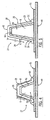
- Fig. 5 shows third and fourth leg portions 24,25 of the composite forming tool 20 changing size during the heating of the composite materials 52,51 to a greater degree than first and second leg portions 22,23 of the composite forming tool 20 . Also in Fig.
- tooling mandrel 30 expands during the heating of the composite material, typically to a greater degree than the first and second leg portions 22,23 but in an amount less than or equal to the expansion of the third and fourth leg portions 24,25 .
- the relative change in size of composite forming tool 20 as seen when comparing Fig. 4 to Fig. 5 is not generally the typical magnitude of expansion, but has been exaggerated for purposes of illustration.
- the line A between the first and third leg portions 22,24 and the line B between the second and fourth leg portions 23,25 are for illustration purposes only and are not generally visible. Both lines A,B help to show how the third and fourth leg portions 24,25 expand more than the first and second leg portions 22,23 .
- FIG. 4 roughly divides the unheated first leg 27 into 2 equal portions, first and third leg portions 22,24 .
- Fig. 4 shows that the length of the first leg portion 22 , length L1 , is roughly the same as the length of the third leg portion 24 , length L3 .
- the curing process which takes place in Fig. 5 , causes the third leg portion 24 to expand to a greater degree than that of the first leg portion 22 because, as previously discussed; of the difference in the coefficient of thermal expansion of the materials that make up the separate leg portions.
- the length L3 of the third leg portion 24 is shown to increase during the curing process, while the length L1 of the first leg portion 22 is not shown to increase as much as length L3 .
- Fig. 5 shows that line A no longer divides first leg 27 into roughly two equal portions, but, instead, the third leg portion 24 now forms more than half of the overall leg as a result of third leg portion 24 expanding to a greater degree than first leg portion 22 .
- the second and fourth leg portions 23,25 which form the second leg 28 , also expand in lesser and greater amounts, respectively, during the curing process in the same manner as discussed above in connection with the first leg 27 .
- the composite forming apparatus 10 and composite material 51,52 are cooled and the composite forming tool 20 and tooling mandrel 30 are thereafter removed. Both the composite forming tool 20 and the tooling mandrel 30 may be reused for the production of multiple composite parts. Then, the composite part, such as a hat stiffened composite part 50 , is removed from the base bond tool 40 . After cooling down, the composite may retain the shape it had during curing because of the resin curing and solidifying. In other embodiments, different types of composite parts may be formed.
- first and second leg portions 22,23 By forming the first and second leg portions 22,23 with material that does not expand to as great a degree as the other portions of the leg, a corner shape can be constrained or held within tolerances during fabrication, which is desirable with respect to the integrity of composite parts. As such, the corners defined between the foot portions 21 and the first and second leg portions 22,23 can be formed to a more exacting tolerance than other portions of the composite part, such as the corners between the third and fourth leg portions 24,25 and the interconnecting portion 26 .
- the composite forming tool 20 is configured to form composite parts that meet even quite exacting tolerances for some of the features while still permitting the inevitable expansion of the composite material and the tooling mandrel 30 which occurs during the curing process.
- the composite forming apparatus 10 may have other shapes and/or other portions of the composite forming tool 20 may be formed of less thermally expansive material.
- the composite forming tool 20 will include less thermally expansive material with a lower coefficient of thermal expansion proximate those features of the composite part that have smaller tolerances and more thermally expansive material with a greater coefficient of thermal expansion proximate those other features of the composite part that have looser tolerances, with the expansion of the composite material 51,52 and/or the tooling mandrel 30 predominately accommodated by the expansion of those portions of the composite forming tool 20 formed of the more thermally expansive material. Therefore, it is to be understood that the inventions are not to be limited to the specific embodiments disclosed and that modifications and other embodiments are intended to be included within the scope of the appended claims. Although specific terms are employed herein, they are used in a generic and descriptive sense only and not for purposes of limitation.
Landscapes
- Engineering & Computer Science (AREA)
- Mechanical Engineering (AREA)
- Chemical & Material Sciences (AREA)
- Composite Materials (AREA)
- Architecture (AREA)
- Civil Engineering (AREA)
- Structural Engineering (AREA)
- Manufacturing & Machinery (AREA)
- Moulding By Coating Moulds (AREA)
- Moulds For Moulding Plastics Or The Like (AREA)
Claims (11)
- Verbundwerkstoffformwerkzeug (20), das aufweist:einen ersten (22) und einen zweiten (23) Schenkelbereich, die mit entsprechenden Fußbereichen (21) verbunden sind;einen dritten (24) und einen vierten (25) Schenkelbereich, die jeweils mit dem ersten bzw. dem zweiten Schenkelbereich (22, 23) verbunden sind; undeinen Verbindungsbereich (26), der sich zwischen dem dritten und dem vierten Schenkelbereich (24, 25) erstreckt und diese verbindet, wobei der erste und der zweite Schenkelbereich (22, 23) des Verbundwerkstoffformwerkzeugs ein Material aufweisen, das thermisch weniger ausdehnungsfähig ist als ein Material, das den dritten und den vierten Schenkelbereich (24, 25) und den Verbindungsbereich (26) bildet, dadurch gekennzeichnet, dassder erste und der zweite Schenkelbereich (22, 23) an einem ihrer Enden mit den Fußbereichen (21) und an ihrem anderen Ende jeweils entsprechend mit dem dritten und dem vierten Schenkelbereich (24, 25) verbunden sind und der dritte und der vierte Schenkelbereich (24, 25) an deren anderen Ende mit dem Verbindungsbereich (26) verbunden sind.
- Verbundwerkstoffformwerkzeug (20) nach Anspruch 1, wobei der erste und der zweite Schenkelbereich (22, 23) ein Fluorelastomer aufweisen.
- Verbundwerkstoffformwerkzeug (20) nach Anspruch 1, wobei der dritte und der vierte Schenkelbereich (24, 25) und der Verbindungsbereich (26) einen Siliconkautschuk aufweisen.
- Verbundwerkstoffformwerkzeug (20) nach Anspruch 1, wobei die Fußbereiche (21) des ersten und des zweiten Schenkelbereichs (22, 23) parallel zu dem Verbindungsbereich (26) verlaufen.
- Verbundwerkstoffformwerkzeug (20) nach Anspruch 1, wobei der erste (22) und der dritte (24) Schenkelbereich und der zweite (23) und der vierte (25) Schenkelbereich jeweils planare Oberflächen definieren.
- Verbundwerkstoffformwerkzeug (20) nach Anspruch 1, wobei der erste und der zweite Schenkelbereich (22, 23) ein Fluorelastomer mit Faserverstärkung aufweisen.
- Verfahren zur Herstellung eines Verbundwerkstoffteils, das umfasst:Anordnen eines anfänglichen Verbundwerkstoffes auf einer Werkzeuggrundplatte (40);Anordnen eines Werkzeugdorns (30) auf dem Verbundmaterial; Anordnen eines zusätzlichen Verbundwerkstoffes (52) über dem Werkzeugdorn;Abdecken zumindest eines Teils des über dem Werkzeugdorn liegenden Verbundwerkstoffes mit einem Verbundwerkstoffformwerkzeug (20);Erwärmen des Verbundwerkstoffes, um den Verbundwerkstoff zumindest zum Teil zu härten; undZulassen, dass ein erster Abschnitt (24, 25, 26) des Verbundwerkstoffformwerkzeugs (20) während des Erwärmens des Verbundwerkstoffes seine Größe stärker ändert als ein zweiter Abschnitt des Verbundwerkstoffformwerkzeugs, wobei sich der zweite Abschnitt (21, 22, 23) des Verbundwerkstoffformwerkzeugs näher an der Werkzeuggrundplatte (40) befindet als der erste Abschnitt des Verbundwerkstoffformwerkzeugs.
- Verfahren zur Herstellung eines Verbundwerkstoffteils nach Anspruch 7, das ferner umfasst, einen Druck auf das Verbundmaterial auszuüben, während es erwärmt wird.
- Verfahren zur Herstellung eines Verbundwerkstoffteils nach Anspruch 7, wobei das Erwärmen des Verbundwerkstoffes umfasst, den Verbundwerkstoff Strahlungswärme auszusetzen.
- Verfahren zur Herstellung eines Verbundwerkstoffteils nach Anspruch 7, wobei das Zulassen der Größenänderung des ersten Abschnitts des Verbundwerkstoffformwerkzeugs umfasst, zuzulassen, dass der erste Abschnitt des Verbundwerkstoffformwerkzeugs stärker expandiert als der zweite Abschnitt des Verbundwerkstoffformwerkzeugs.
- Verfahren zur Herstellung eines Verbundwerkstoffteils nach Anspruch 7, worin ferner zugelassen wird, dass sich der Werkzeugdorn während des Erwärmens des Verbundwerkstoffes ebenfalls ausdehnt.
Applications Claiming Priority (2)
| Application Number | Priority Date | Filing Date | Title |
|---|---|---|---|
| US11/561,602 US7854874B2 (en) | 2006-11-20 | 2006-11-20 | Apparatus and methods for forming hat stiffened composite parts using thermally expansive tooling cauls |
| PCT/US2007/085124 WO2008064168A2 (en) | 2006-11-20 | 2007-11-19 | Apparatus and methods for forming hat stiffened composite parts using thermally expansive tooling cauls |
Publications (2)
| Publication Number | Publication Date |
|---|---|
| EP2091720A2 EP2091720A2 (de) | 2009-08-26 |
| EP2091720B1 true EP2091720B1 (de) | 2015-11-18 |
Family
ID=39327174
Family Applications (1)
| Application Number | Title | Priority Date | Filing Date |
|---|---|---|---|
| EP07864611.4A Active EP2091720B1 (de) | 2006-11-20 | 2007-11-19 | Vorrichtung und verfahren zur herstellung haubenversteifter verbundteile mit wärmeausdehnungsfähigen werkzeugbeschickblechen |
Country Status (6)
| Country | Link |
|---|---|
| US (2) | US7854874B2 (de) |
| EP (1) | EP2091720B1 (de) |
| JP (1) | JP5424891B2 (de) |
| CN (1) | CN101541513B (de) |
| ES (1) | ES2555155T3 (de) |
| WO (1) | WO2008064168A2 (de) |
Families Citing this family (30)
| Publication number | Priority date | Publication date | Assignee | Title |
|---|---|---|---|---|
| US8043554B2 (en) * | 2007-06-08 | 2011-10-25 | The Boeing Company | Manufacturing process using bladderless mold line conformal hat stringer |
| US20080302912A1 (en) * | 2007-06-08 | 2008-12-11 | The Boeing Company | Bladderless Mold Line Conformal Hat Stringer |
| EP2440395B1 (de) * | 2009-06-12 | 2014-11-19 | Alenia Aermacchi S.p.A. | Verfahren zur herstellung versteifter platten aus verbundwerkstoff |
| FR2959694B1 (fr) * | 2010-05-10 | 2012-08-03 | Lorraine Construction Aeronautique | Dispositif pour la fabrication d'une piece composite par injection de resine |
| FR2963272B1 (fr) * | 2010-07-29 | 2012-08-17 | Airbus Operations Sas | Procede de fabrication d'un panneau raidi en materiau composite |
| US8556618B2 (en) * | 2011-04-07 | 2013-10-15 | Spirit Aerosystems, Inc. | Method and bladder apparatus for forming composite parts |
| FR2985213B1 (fr) * | 2011-12-28 | 2016-12-30 | Airbus Operations Sas | Panneau composite auto-raidi et procede de realisation |
| US9126355B2 (en) * | 2012-05-02 | 2015-09-08 | Spirit Aerosystems, Inc. | Composite material part manufacturing process using removable and retainable material |
| US20130299073A1 (en) * | 2012-05-08 | 2013-11-14 | Lockheed Martin Corporation | Contour caul with expansion region |
| FR2991228B1 (fr) | 2012-05-29 | 2015-03-06 | Airbus Operations Sas | Procede et dispositif de realisation d'un panneau composite auto-raidi |
| US9333713B2 (en) | 2012-10-04 | 2016-05-10 | The Boeing Company | Method for co-curing composite skins and stiffeners in an autoclave |
| US8986484B2 (en) * | 2012-10-10 | 2015-03-24 | The Boeing Company | Shape-distorting tooling system and method for curing composite parts |
| US9498903B2 (en) * | 2012-10-31 | 2016-11-22 | The Boeing Company | System and method for manufacturing monolithic structures using expanding internal tools |
| FR2999970B1 (fr) | 2012-12-20 | 2015-06-19 | Airbus Operations Sas | Procede de realisation d'une preforme textile a fibres continues par circulation d'un flux de gaz chaud a travers un ensemble fibreux |
| US10308343B2 (en) | 2013-05-30 | 2019-06-04 | The Boeing Company | Composite hat stiffener |
| US9623620B2 (en) * | 2013-12-19 | 2017-04-18 | Embraer S.A. | Three-dimensional reuseable curing caul for use in curing integrated composite components and methods of making the same |
| FR3015433B1 (fr) | 2013-12-23 | 2016-02-12 | Airbus Operations Sas | Ensemble pour aeronef comprenant un mat d'accrochage integre a la nacelle et agence en partie arriere du fuselage |
| US11577432B2 (en) * | 2014-06-03 | 2023-02-14 | Kenji Kingsford | Composite structure reinforcement utilizing thermal properties of forming elements |
| US10449734B2 (en) * | 2014-09-18 | 2019-10-22 | Alenia Aermacchi S.P.A. | Methods for manufacturing elongated structural elements of composite material |
| CN104924628B (zh) * | 2015-04-29 | 2017-06-06 | 中航复合材料有限责任公司 | 整体复合材料加筋筒体的成型方法、铺叠工装、固化模和长桁定位装置 |
| US10807280B2 (en) * | 2015-06-22 | 2020-10-20 | The Boeing Company | Method of extracting a tooling mandrel from a composite laminate cavity |
| US11104113B2 (en) | 2017-04-19 | 2021-08-31 | The Boeing Company | Systems and methods for assembling elongate composite structures |
| EP3659774B1 (de) * | 2017-07-25 | 2023-05-31 | Subaru Corporation | Verbundstoffmaterialformgestell und verbundstoffmaterialformverfahren |
| JP7337051B2 (ja) | 2017-10-12 | 2023-09-01 | アルバニー エンジニアード コンポジッツ インコーポレイテッド | オメガ形状補強材の三次元織物プリフォーム |
| CN110757830B (zh) * | 2018-07-26 | 2022-07-26 | 中国商用飞机有限责任公司 | 一种帽型长桁的热隔膜成型方法 |
| US11155047B2 (en) * | 2018-10-08 | 2021-10-26 | Textron Innovations Inc. | Caul body and a method for forming a composite structure |
| US11198267B2 (en) * | 2018-10-29 | 2021-12-14 | The Boeing Company | Bulk factor compensated tool for fabrication of a composite part |
| JP6570160B1 (ja) * | 2019-03-04 | 2019-09-04 | 日本飛行機株式会社 | 圧力パッド、圧力パッドの製造方法およびハニカムコアサンドイッチ構造体の製造方法 |
| CN117203125A (zh) * | 2020-12-28 | 2023-12-08 | 列奥纳多股份公司 | 用于制造复合材料制成的、用加劲桁条增强的结构部件的方法和结构部件 |
| US12053942B2 (en) * | 2022-01-07 | 2024-08-06 | The Boeing Company | Stringer manufacturing system using a caul |
Family Cites Families (25)
| Publication number | Priority date | Publication date | Assignee | Title |
|---|---|---|---|---|
| US3745204A (en) * | 1971-09-07 | 1973-07-10 | Sfs Ind | Process for making improved seals |
| US3995081A (en) * | 1974-10-07 | 1976-11-30 | General Dynamics Corporation | Composite structural beams and method |
| GB1604872A (en) * | 1978-03-29 | 1981-12-16 | Rohm & Haas | Reinforcing a layer of plastics material |
| JPS6172529A (ja) * | 1984-09-17 | 1986-04-14 | Mitsui Toatsu Chem Inc | 複合材料の製法 |
| GB2173144B (en) * | 1985-04-02 | 1989-08-09 | Rolls Royce Plc | Moulding of composite materials |
| US4822436A (en) * | 1986-03-07 | 1989-04-18 | Northrop Corporation | Apparatus for debulking and autoclaving laminates of complex shapes |
| US5071338A (en) * | 1987-09-08 | 1991-12-10 | United Technologies Corporation | Tool for forming complex composite articles |
| JPH0183524U (de) * | 1987-11-20 | 1989-06-02 | ||
| DE3885717T2 (de) * | 1987-12-03 | 1994-03-31 | United Technologies Corp | Werkzeug und Verfahren zum Formen von komplexen Gegenständen aus Verbundwerkstoff. |
| US4836765A (en) * | 1987-12-03 | 1989-06-06 | United Technologies Corporation | Molding apparatus for composite materials |
| JP3016786B2 (ja) * | 1988-12-27 | 2000-03-06 | 日産自動車株式会社 | 繊維強化樹脂部材の製造方法 |
| US5002476A (en) * | 1989-11-24 | 1991-03-26 | Lockheed Corporation | Tooling for composite parts |
| JP3193064B2 (ja) * | 1991-04-22 | 2001-07-30 | 富士重工業株式会社 | 複合材料の一体成形方法 |
| US5190773A (en) * | 1991-11-18 | 1993-03-02 | United Technologies Corporation | Mold for fabricating composite articles having integrally bonded stiffening members |
| US5242523A (en) * | 1992-05-14 | 1993-09-07 | The Boeing Company | Caul and method for bonding and curing intricate composite structures |
| US5354195A (en) * | 1992-12-23 | 1994-10-11 | United Technologies Corporation | Composite molding apparatus for high pressure co-cure molding of lightweight honeycomb core composite articles having ramped surfaces utilizing low density, stabilized ramped honeycomb cores |
| JPH0852812A (ja) * | 1994-08-12 | 1996-02-27 | Mitsubishi Heavy Ind Ltd | 複合材加圧成形治具及び複合材成形体の製造方法 |
| JPH09300384A (ja) * | 1996-05-13 | 1997-11-25 | Nippon Zeon Co Ltd | 反応射出成形品の製造方法および金型装置 |
| US6217000B1 (en) * | 1996-10-25 | 2001-04-17 | The Boeing Company | Composite fabrication method and tooling to improve part consolidation |
| US5817269A (en) * | 1996-10-25 | 1998-10-06 | The Boeing Company | Composite fabrication method and tooling to improve part consolidation |
| JP3698517B2 (ja) * | 1997-04-25 | 2005-09-21 | 富士重工業株式会社 | 複合材の成形装置 |
| EP1238785B1 (de) | 2001-03-05 | 2004-04-28 | Swiss Luggage SL AG | Verfahren zur Herstellung eines profilierten, schalenartigen Gegenstands sowie eine hierzu verwendbare Form |
| JP4713778B2 (ja) * | 2001-07-24 | 2011-06-29 | 富士重工業株式会社 | 翼構造およびその製造方法 |
| US8632653B2 (en) * | 2005-05-03 | 2014-01-21 | The Boeing Company | Method of manufacturing curved composite structural elements |
| US7824171B2 (en) * | 2005-10-31 | 2010-11-02 | The Boeing Company | Corner-consolidating inflatable apparatus and method for manufacturing composite structures |
-
2006
- 2006-11-20 US US11/561,602 patent/US7854874B2/en active Active
-
2007
- 2007-11-19 CN CN2007800431000A patent/CN101541513B/zh active Active
- 2007-11-19 WO PCT/US2007/085124 patent/WO2008064168A2/en not_active Ceased
- 2007-11-19 JP JP2009538477A patent/JP5424891B2/ja active Active
- 2007-11-19 ES ES07864611.4T patent/ES2555155T3/es active Active
- 2007-11-19 EP EP07864611.4A patent/EP2091720B1/de active Active
-
2010
- 2010-10-15 US US12/905,770 patent/US8523553B2/en active Active
Also Published As
| Publication number | Publication date |
|---|---|
| WO2008064168A2 (en) | 2008-05-29 |
| ES2555155T3 (es) | 2015-12-29 |
| US20080116618A1 (en) | 2008-05-22 |
| US8523553B2 (en) | 2013-09-03 |
| US20110024052A1 (en) | 2011-02-03 |
| WO2008064168A3 (en) | 2008-07-24 |
| US7854874B2 (en) | 2010-12-21 |
| EP2091720A2 (de) | 2009-08-26 |
| JP5424891B2 (ja) | 2014-02-26 |
| JP2010510111A (ja) | 2010-04-02 |
| CN101541513B (zh) | 2012-08-22 |
| CN101541513A (zh) | 2009-09-23 |
Similar Documents
| Publication | Publication Date | Title |
|---|---|---|
| EP2091720B1 (de) | Vorrichtung und verfahren zur herstellung haubenversteifter verbundteile mit wärmeausdehnungsfähigen werkzeugbeschickblechen | |
| US10286577B2 (en) | Composite mandrel for autoclave curing applications | |
| US8337740B2 (en) | Reinforced internal composite structures | |
| JP7619758B2 (ja) | 複合部品用の内部ツーリング | |
| JP5315713B2 (ja) | Frp製部材用プリフォームの製造方法 | |
| US8758664B2 (en) | Method for forming composite components and tool for use therein | |
| CN114269548B (zh) | 用于制造由纤维复合材料构成的构件的方法和装置 | |
| JPS6228742B2 (de) | ||
| JP2010540294A (ja) | 被成形材の成形方法 | |
| CN105873745B (zh) | Frp成型夹具和frp结构体的成型方法 | |
| CA2741486A1 (en) | Manufacturing method of a complex geometry panel in prepreg composite material | |
| CN101815606A (zh) | 用于生产部件的方法以及纤维增强热塑性部件 | |
| CN106864769B (zh) | 使用铰接式芯轴的复合飞机制造工具和方法 | |
| Jain et al. | Spring-in study of the aileron rib manufactured from advanced thermoplastic composite | |
| JP2003071864A (ja) | 複合材補強板の製造方法 | |
| US20200130291A1 (en) | Bulk Factor Compensated Tool for Fabrication of a Composite Part | |
| US20200122361A1 (en) | Mandrel for Processing a Composite Part and Method for Fabricating a Composite Part | |
| WO2019188195A1 (ja) | 繊維強化樹脂の製造方法 | |
| WO2011015823A1 (en) | Composite tool pin | |
| US20090218723A1 (en) | Automated prototyping of a composite airframe | |
| US11478958B2 (en) | Multi-component mandrel for processing a composite part and method for fabricating a composite part | |
| JP4941811B2 (ja) | プリフォーム、frp成形体の製造方法 | |
| WO2014099841A1 (en) | Expandable mandrel and method of making hollow composite structures | |
| US11110671B2 (en) | Layup support configured to provide support for laying up composite material | |
| CN114055804B (zh) | 结构体的制造方法和结构体 |
Legal Events
| Date | Code | Title | Description |
|---|---|---|---|
| PUAI | Public reference made under article 153(3) epc to a published international application that has entered the european phase |
Free format text: ORIGINAL CODE: 0009012 |
|
| 17P | Request for examination filed |
Effective date: 20090506 |
|
| AK | Designated contracting states |
Kind code of ref document: A2 Designated state(s): AT BE BG CH CY CZ DE DK EE ES FI FR GB GR HU IE IS IT LI LT LU LV MC MT NL PL PT RO SE SI SK TR |
|
| DAX | Request for extension of the european patent (deleted) | ||
| 17Q | First examination report despatched |
Effective date: 20100203 |
|
| GRAP | Despatch of communication of intention to grant a patent |
Free format text: ORIGINAL CODE: EPIDOSNIGR1 |
|
| INTG | Intention to grant announced |
Effective date: 20150528 |
|
| GRAS | Grant fee paid |
Free format text: ORIGINAL CODE: EPIDOSNIGR3 |
|
| GRAA | (expected) grant |
Free format text: ORIGINAL CODE: 0009210 |
|
| REG | Reference to a national code |
Ref country code: FR Ref legal event code: PLFP Year of fee payment: 9 |
|
| AK | Designated contracting states |
Kind code of ref document: B1 Designated state(s): AT BE BG CH CY CZ DE DK EE ES FI FR GB GR HU IE IS IT LI LT LU LV MC MT NL PL PT RO SE SI SK TR |
|
| REG | Reference to a national code |
Ref country code: GB Ref legal event code: FG4D |
|
| REG | Reference to a national code |
Ref country code: CH Ref legal event code: EP |
|
| REG | Reference to a national code |
Ref country code: AT Ref legal event code: REF Ref document number: 761317 Country of ref document: AT Kind code of ref document: T Effective date: 20151215 |
|
| REG | Reference to a national code |
Ref country code: IE Ref legal event code: FG4D |
|
| REG | Reference to a national code |
Ref country code: ES Ref legal event code: FG2A Ref document number: 2555155 Country of ref document: ES Kind code of ref document: T3 Effective date: 20151229 |
|
| REG | Reference to a national code |
Ref country code: DE Ref legal event code: R096 Ref document number: 602007044031 Country of ref document: DE |
|
| REG | Reference to a national code |
Ref country code: NL Ref legal event code: MP Effective date: 20160218 |
|
| REG | Reference to a national code |
Ref country code: LT Ref legal event code: MG4D |
|
| REG | Reference to a national code |
Ref country code: AT Ref legal event code: MK05 Ref document number: 761317 Country of ref document: AT Kind code of ref document: T Effective date: 20151118 |
|
| PG25 | Lapsed in a contracting state [announced via postgrant information from national office to epo] |
Ref country code: IS Free format text: LAPSE BECAUSE OF FAILURE TO SUBMIT A TRANSLATION OF THE DESCRIPTION OR TO PAY THE FEE WITHIN THE PRESCRIBED TIME-LIMIT Effective date: 20160318 Ref country code: NL Free format text: LAPSE BECAUSE OF FAILURE TO SUBMIT A TRANSLATION OF THE DESCRIPTION OR TO PAY THE FEE WITHIN THE PRESCRIBED TIME-LIMIT Effective date: 20151118 Ref country code: LT Free format text: LAPSE BECAUSE OF FAILURE TO SUBMIT A TRANSLATION OF THE DESCRIPTION OR TO PAY THE FEE WITHIN THE PRESCRIBED TIME-LIMIT Effective date: 20151118 |
|
| PG25 | Lapsed in a contracting state [announced via postgrant information from national office to epo] |
Ref country code: SE Free format text: LAPSE BECAUSE OF FAILURE TO SUBMIT A TRANSLATION OF THE DESCRIPTION OR TO PAY THE FEE WITHIN THE PRESCRIBED TIME-LIMIT Effective date: 20151118 Ref country code: LV Free format text: LAPSE BECAUSE OF FAILURE TO SUBMIT A TRANSLATION OF THE DESCRIPTION OR TO PAY THE FEE WITHIN THE PRESCRIBED TIME-LIMIT Effective date: 20151118 Ref country code: PT Free format text: LAPSE BECAUSE OF FAILURE TO SUBMIT A TRANSLATION OF THE DESCRIPTION OR TO PAY THE FEE WITHIN THE PRESCRIBED TIME-LIMIT Effective date: 20160318 Ref country code: BE Free format text: LAPSE BECAUSE OF NON-PAYMENT OF DUE FEES Effective date: 20151130 Ref country code: GR Free format text: LAPSE BECAUSE OF FAILURE TO SUBMIT A TRANSLATION OF THE DESCRIPTION OR TO PAY THE FEE WITHIN THE PRESCRIBED TIME-LIMIT Effective date: 20160219 Ref country code: PL Free format text: LAPSE BECAUSE OF FAILURE TO SUBMIT A TRANSLATION OF THE DESCRIPTION OR TO PAY THE FEE WITHIN THE PRESCRIBED TIME-LIMIT Effective date: 20151118 Ref country code: FI Free format text: LAPSE BECAUSE OF FAILURE TO SUBMIT A TRANSLATION OF THE DESCRIPTION OR TO PAY THE FEE WITHIN THE PRESCRIBED TIME-LIMIT Effective date: 20151118 Ref country code: AT Free format text: LAPSE BECAUSE OF FAILURE TO SUBMIT A TRANSLATION OF THE DESCRIPTION OR TO PAY THE FEE WITHIN THE PRESCRIBED TIME-LIMIT Effective date: 20151118 |
|
| REG | Reference to a national code |
Ref country code: CH Ref legal event code: PL |
|
| PG25 | Lapsed in a contracting state [announced via postgrant information from national office to epo] |
Ref country code: LI Free format text: LAPSE BECAUSE OF NON-PAYMENT OF DUE FEES Effective date: 20151130 Ref country code: CZ Free format text: LAPSE BECAUSE OF FAILURE TO SUBMIT A TRANSLATION OF THE DESCRIPTION OR TO PAY THE FEE WITHIN THE PRESCRIBED TIME-LIMIT Effective date: 20151118 Ref country code: CH Free format text: LAPSE BECAUSE OF NON-PAYMENT OF DUE FEES Effective date: 20151130 |
|
| REG | Reference to a national code |
Ref country code: DE Ref legal event code: R097 Ref document number: 602007044031 Country of ref document: DE |
|
| REG | Reference to a national code |
Ref country code: IE Ref legal event code: MM4A |
|
| PG25 | Lapsed in a contracting state [announced via postgrant information from national office to epo] |
Ref country code: EE Free format text: LAPSE BECAUSE OF FAILURE TO SUBMIT A TRANSLATION OF THE DESCRIPTION OR TO PAY THE FEE WITHIN THE PRESCRIBED TIME-LIMIT Effective date: 20151118 Ref country code: DK Free format text: LAPSE BECAUSE OF FAILURE TO SUBMIT A TRANSLATION OF THE DESCRIPTION OR TO PAY THE FEE WITHIN THE PRESCRIBED TIME-LIMIT Effective date: 20151118 Ref country code: RO Free format text: LAPSE BECAUSE OF FAILURE TO SUBMIT A TRANSLATION OF THE DESCRIPTION OR TO PAY THE FEE WITHIN THE PRESCRIBED TIME-LIMIT Effective date: 20151118 Ref country code: SK Free format text: LAPSE BECAUSE OF FAILURE TO SUBMIT A TRANSLATION OF THE DESCRIPTION OR TO PAY THE FEE WITHIN THE PRESCRIBED TIME-LIMIT Effective date: 20151118 |
|
| PLBE | No opposition filed within time limit |
Free format text: ORIGINAL CODE: 0009261 |
|
| STAA | Information on the status of an ep patent application or granted ep patent |
Free format text: STATUS: NO OPPOSITION FILED WITHIN TIME LIMIT |
|
| PG25 | Lapsed in a contracting state [announced via postgrant information from national office to epo] |
Ref country code: MC Free format text: LAPSE BECAUSE OF FAILURE TO SUBMIT A TRANSLATION OF THE DESCRIPTION OR TO PAY THE FEE WITHIN THE PRESCRIBED TIME-LIMIT Effective date: 20151118 |
|
| 26N | No opposition filed |
Effective date: 20160819 |
|
| PG25 | Lapsed in a contracting state [announced via postgrant information from national office to epo] |
Ref country code: IE Free format text: LAPSE BECAUSE OF NON-PAYMENT OF DUE FEES Effective date: 20151119 |
|
| REG | Reference to a national code |
Ref country code: FR Ref legal event code: PLFP Year of fee payment: 10 |
|
| PG25 | Lapsed in a contracting state [announced via postgrant information from national office to epo] |
Ref country code: SI Free format text: LAPSE BECAUSE OF FAILURE TO SUBMIT A TRANSLATION OF THE DESCRIPTION OR TO PAY THE FEE WITHIN THE PRESCRIBED TIME-LIMIT Effective date: 20151118 |
|
| PG25 | Lapsed in a contracting state [announced via postgrant information from national office to epo] |
Ref country code: BE Free format text: LAPSE BECAUSE OF FAILURE TO SUBMIT A TRANSLATION OF THE DESCRIPTION OR TO PAY THE FEE WITHIN THE PRESCRIBED TIME-LIMIT Effective date: 20151118 |
|
| PG25 | Lapsed in a contracting state [announced via postgrant information from national office to epo] |
Ref country code: HU Free format text: LAPSE BECAUSE OF FAILURE TO SUBMIT A TRANSLATION OF THE DESCRIPTION OR TO PAY THE FEE WITHIN THE PRESCRIBED TIME-LIMIT; INVALID AB INITIO Effective date: 20071119 Ref country code: BG Free format text: LAPSE BECAUSE OF FAILURE TO SUBMIT A TRANSLATION OF THE DESCRIPTION OR TO PAY THE FEE WITHIN THE PRESCRIBED TIME-LIMIT Effective date: 20151118 |
|
| PG25 | Lapsed in a contracting state [announced via postgrant information from national office to epo] |
Ref country code: CY Free format text: LAPSE BECAUSE OF FAILURE TO SUBMIT A TRANSLATION OF THE DESCRIPTION OR TO PAY THE FEE WITHIN THE PRESCRIBED TIME-LIMIT Effective date: 20151118 |
|
| PG25 | Lapsed in a contracting state [announced via postgrant information from national office to epo] |
Ref country code: MT Free format text: LAPSE BECAUSE OF FAILURE TO SUBMIT A TRANSLATION OF THE DESCRIPTION OR TO PAY THE FEE WITHIN THE PRESCRIBED TIME-LIMIT Effective date: 20151118 Ref country code: TR Free format text: LAPSE BECAUSE OF FAILURE TO SUBMIT A TRANSLATION OF THE DESCRIPTION OR TO PAY THE FEE WITHIN THE PRESCRIBED TIME-LIMIT Effective date: 20151118 |
|
| REG | Reference to a national code |
Ref country code: FR Ref legal event code: PLFP Year of fee payment: 11 |
|
| PG25 | Lapsed in a contracting state [announced via postgrant information from national office to epo] |
Ref country code: LU Free format text: LAPSE BECAUSE OF NON-PAYMENT OF DUE FEES Effective date: 20151119 |
|
| P01 | Opt-out of the competence of the unified patent court (upc) registered |
Effective date: 20230516 |
|
| PGFP | Annual fee paid to national office [announced via postgrant information from national office to epo] |
Ref country code: DE Payment date: 20251128 Year of fee payment: 19 |
|
| PGFP | Annual fee paid to national office [announced via postgrant information from national office to epo] |
Ref country code: GB Payment date: 20251127 Year of fee payment: 19 |
|
| PGFP | Annual fee paid to national office [announced via postgrant information from national office to epo] |
Ref country code: IT Payment date: 20251119 Year of fee payment: 19 |
|
| PGFP | Annual fee paid to national office [announced via postgrant information from national office to epo] |
Ref country code: FR Payment date: 20251125 Year of fee payment: 19 |
|
| PGFP | Annual fee paid to national office [announced via postgrant information from national office to epo] |
Ref country code: ES Payment date: 20251201 Year of fee payment: 19 |