EP2091787B1 - Dispositif d'absorption d'énergie - Google Patents
Dispositif d'absorption d'énergie Download PDFInfo
- Publication number
- EP2091787B1 EP2091787B1 EP07846911A EP07846911A EP2091787B1 EP 2091787 B1 EP2091787 B1 EP 2091787B1 EP 07846911 A EP07846911 A EP 07846911A EP 07846911 A EP07846911 A EP 07846911A EP 2091787 B1 EP2091787 B1 EP 2091787B1
- Authority
- EP
- European Patent Office
- Prior art keywords
- hollow longitudinal
- energy absorption
- longitudinal section
- absorption device
- section
- Prior art date
- Legal status (The legal status is an assumption and is not a legal conclusion. Google has not performed a legal analysis and makes no representation as to the accuracy of the status listed.)
- Not-in-force
Links
- 238000010521 absorption reaction Methods 0.000 title claims abstract description 75
- 230000007704 transition Effects 0.000 claims description 23
- 238000000034 method Methods 0.000 claims description 13
- 238000004519 manufacturing process Methods 0.000 description 9
- 229910000831 Steel Inorganic materials 0.000 description 7
- 239000000463 material Substances 0.000 description 7
- 239000010959 steel Substances 0.000 description 7
- 238000005096 rolling process Methods 0.000 description 4
- 238000000418 atomic force spectrum Methods 0.000 description 3
- 230000002349 favourable effect Effects 0.000 description 3
- 230000002093 peripheral effect Effects 0.000 description 3
- 238000004088 simulation Methods 0.000 description 3
- 244000089486 Phragmites australis subsp australis Species 0.000 description 2
- 230000000694 effects Effects 0.000 description 2
- 238000005304 joining Methods 0.000 description 2
- 230000035939 shock Effects 0.000 description 2
- 239000000853 adhesive Substances 0.000 description 1
- 230000001070 adhesive effect Effects 0.000 description 1
- 230000004323 axial length Effects 0.000 description 1
- 238000005452 bending Methods 0.000 description 1
- 238000010586 diagram Methods 0.000 description 1
- 238000006073 displacement reaction Methods 0.000 description 1
- 239000002994 raw material Substances 0.000 description 1
- 238000005476 soldering Methods 0.000 description 1
- 238000007711 solidification Methods 0.000 description 1
- 230000008023 solidification Effects 0.000 description 1
- 230000006641 stabilisation Effects 0.000 description 1
- 238000011105 stabilization Methods 0.000 description 1
- 230000000087 stabilizing effect Effects 0.000 description 1
- 239000007858 starting material Substances 0.000 description 1
- 238000003860 storage Methods 0.000 description 1
- 238000005482 strain hardening Methods 0.000 description 1
- 238000011144 upstream manufacturing Methods 0.000 description 1
- 238000003466 welding Methods 0.000 description 1
Images






Classifications
-
- B—PERFORMING OPERATIONS; TRANSPORTING
- B60—VEHICLES IN GENERAL
- B60R—VEHICLES, VEHICLE FITTINGS, OR VEHICLE PARTS, NOT OTHERWISE PROVIDED FOR
- B60R19/00—Wheel guards; Radiator guards, e.g. grilles; Obstruction removers; Fittings damping bouncing force in collisions
- B60R19/02—Bumpers, i.e. impact receiving or absorbing members for protecting vehicles or fending off blows from other vehicles or objects
- B60R19/24—Arrangements for mounting bumpers on vehicles
- B60R19/26—Arrangements for mounting bumpers on vehicles comprising yieldable mounting means
- B60R19/34—Arrangements for mounting bumpers on vehicles comprising yieldable mounting means destroyed upon impact, e.g. one-shot type
-
- B—PERFORMING OPERATIONS; TRANSPORTING
- B60—VEHICLES IN GENERAL
- B60R—VEHICLES, VEHICLE FITTINGS, OR VEHICLE PARTS, NOT OTHERWISE PROVIDED FOR
- B60R16/00—Electric or fluid circuits specially adapted for vehicles and not otherwise provided for; Arrangement of elements of electric or fluid circuits specially adapted for vehicles and not otherwise provided for
- B60R16/02—Electric or fluid circuits specially adapted for vehicles and not otherwise provided for; Arrangement of elements of electric or fluid circuits specially adapted for vehicles and not otherwise provided for electric constitutive elements
-
- F—MECHANICAL ENGINEERING; LIGHTING; HEATING; WEAPONS; BLASTING
- F16—ENGINEERING ELEMENTS AND UNITS; GENERAL MEASURES FOR PRODUCING AND MAINTAINING EFFECTIVE FUNCTIONING OF MACHINES OR INSTALLATIONS; THERMAL INSULATION IN GENERAL
- F16F—SPRINGS; SHOCK-ABSORBERS; MEANS FOR DAMPING VIBRATION
- F16F7/00—Vibration-dampers; Shock-absorbers
- F16F7/12—Vibration-dampers; Shock-absorbers using plastic deformation of members
-
- F—MECHANICAL ENGINEERING; LIGHTING; HEATING; WEAPONS; BLASTING
- F16—ENGINEERING ELEMENTS AND UNITS; GENERAL MEASURES FOR PRODUCING AND MAINTAINING EFFECTIVE FUNCTIONING OF MACHINES OR INSTALLATIONS; THERMAL INSULATION IN GENERAL
- F16F—SPRINGS; SHOCK-ABSORBERS; MEANS FOR DAMPING VIBRATION
- F16F7/00—Vibration-dampers; Shock-absorbers
- F16F7/12—Vibration-dampers; Shock-absorbers using plastic deformation of members
- F16F7/123—Deformation involving a bending action, e.g. strap moving through multiple rollers, folding of members
-
- Y—GENERAL TAGGING OF NEW TECHNOLOGICAL DEVELOPMENTS; GENERAL TAGGING OF CROSS-SECTIONAL TECHNOLOGIES SPANNING OVER SEVERAL SECTIONS OF THE IPC; TECHNICAL SUBJECTS COVERED BY FORMER USPC CROSS-REFERENCE ART COLLECTIONS [XRACs] AND DIGESTS
- Y10—TECHNICAL SUBJECTS COVERED BY FORMER USPC
- Y10T—TECHNICAL SUBJECTS COVERED BY FORMER US CLASSIFICATION
- Y10T29/00—Metal working
- Y10T29/49—Method of mechanical manufacture
- Y10T29/49826—Assembling or joining
Definitions
- the present invention relates to an energy absorption device having a first hollow longitudinal section of first cross-sectional width and a second hollow longitudinal section of second cross-sectional width and a slipped transition region between the hollow longitudinal sections.
- Such energy absorption devices are used in vehicles and arranged for example between bumper and body. In an accident, they deform plastically and thereby absorb energy. In light accidents, the energy absorption capacity may be sufficient to prevent plastic deformation of the body.
- the energy absorption device is arranged aligned parallel to the vehicle's longitudinal direction.
- the US 6,802,548 B2 suggests the use of a cup-shaped shock absorbing element which is upstream of the energy absorbing device on the bumper side.
- a pivoting of the bumper-side hollow longitudinal section is prevented or at least largely minimized with the aid of the cup-shaped shock absorption element.
- the present invention further relates to an energy absorbing device for a bumper assembly of a vehicle having a hollow longitudinal portion oriented for forming and oriented obliquely to the vehicle longitudinal direction and an adjoining, inverted region to which a mounting portion of the energy absorbing device is provided which defines a mounting plane of the energy absorbing device.
- an energy absorbing device which has a tube intended for reshaping and an inverted area adjoining thereto, to which an attachment piece which extends outwards adjoins.
- the extension is attached to a guide member which is formed as an annular disc.
- the extension piece and the guide part are aligned parallel to the cross-sectional plane of the tube. In this way, the tube can deform correctly undulating and pass through the opening of the guide member.
- the present invention has for its object to improve a generic energy absorption device to the effect that in the simplest possible way obliquely acting accident forces can be absorbed with good efficiency, and to provide a method for producing such an energy absorption device.
- the axial direction of the hollow longitudinal section or the continuation section can be aligned obliquely to a vehicle longitudinal direction and extend the axial direction of the respective other section substantially parallel to the vehicle longitudinal direction.
- oblique accident forces are well received and the forces are still relatively straight into the body introduced, for example, in a side member of the body to which the energy absorption device may be attached.
- the hollow longitudinal portion may be aligned at about 5 ° to 20 ° obliquely to the axial direction of the continuation portion, preferably by about 8 ° to 12 °, more preferably by about 10 °. In this way, oblique accident forces are easy to catch and absorb and yet forces acting parallel to the vehicle longitudinal direction are still easily absorbed and absorbed.
- a guide may be provided, on which rolls the hollow longitudinal section during forming. This results in a telescoping movement with good stability.
- the hollow longitudinal section intended for reshaping can be oriented obliquely to the vehicle longitudinal direction and as a continuation section an attachment section of the energy absorption device can be provided, which defines a mounting plane of the energy absorption device, wherein the mounting plane is aligned in an initial state before an energy absorption obliquely to the transverse direction of the hollow longitudinal section.
- the oblique orientation of the transverse direction of the hollow longitudinal section to the fastening plane are accident forces acting obliquely to the vehicle longitudinal direction well absorbable.
- the forming process is surprisingly easy and can be achieved as an energy absorption efficiency, as in energy absorption devices are possible in which the mounting plane is aligned parallel to the transverse direction of the hollow longitudinal section.
- the mounting plane can be aligned approximately perpendicular to the vehicle longitudinal direction.
- the hollow longitudinal section is aligned obliquely to the vehicle longitudinal direction and can accommodate obliquely acting accident forces substantially corresponding to its longitudinal direction. With the attachment portion, the remaining forces can largely be passed in the vehicle longitudinal direction.
- the inverted portion may be formed at an end portion of the energy absorbing device.
- the everting deformation of the hollow longitudinal section begins at the end of the energy absorbing device.
- the energy absorption device can be fastened to a body structure in the direction of the longitudinal section approximately at the level of the inverted area. In this way, the energy absorbing device can be stored with good stability.
- the hollow longitudinal section can adapt well in its orientation to accident forces whose direction deviates from the original direction of its longitudinal axis.
- the inverted region may have a U-shaped slip-on shape.
- the transition from the longitudinal section to the mounting portion is easy and feasible even in a narrower space.
- the attachment portion may be formed in the manner of a flange, a brim or a collar.
- the energy absorbing device is easily and extensively mounted on a vehicle.
- a vehicle structure having an energy absorption device with at least one of the aforementioned configurations can be provided particularly favorably, the vehicle structure having a wall which forms a guide of the hollow longitudinal section on which it can be unrolled during forming.
- existing structures of a vehicle for example, a side member, in particular an interior thereof. With the rolling the contact of wall and umstülpendem longitudinal section runs smoothly.
- the energy absorbing device may comprise a first hollow longitudinal section of first cross-sectional width and a second longitudinal hollow section of second cross-sectional width, and as an invaginated section an inverted transition section between the hollow longitudinal sections, wherein the first longitudinal hollow section and the second longitudinal hollow section are obliquely aligned in an initial state prior to energy absorption , With the oblique orientation of the hollow longitudinal sections obliquely acting accident forces can be well absorbed and absorbed. In this case, surprisingly, a similarly good force curve is achieved as with energy absorption devices with straight longitudinal sections, that is, a good efficiency in the energy absorption is achieved.
- the stülptex the hollow longitudinal sections can be aligned obliquely to the vehicle direction.
- the oblique accident force can be absorbed very efficiently.
- the longitudinal section intended for reshaping can absorb the accident force in its longitudinal direction.
- the hollow longitudinal section of lesser cross-sectional width can be particularly favorable for the hollowed-out hollow longitudinal section of the energy absorption device.
- the hollow longitudinal section of greater cross-sectional width can be used for stabilizing, it has the wider support apparatus, so to speak.
- the hollow longitudinal section of larger cross-sectional width can form a guide of the hollow longitudinal section of smaller cross-sectional width.
- the longitudinal portion of lesser cross-sectional width can be supported on the longitudinal section of larger cross-sectional width and roll it. This results in a telescoping movement with good stability.
- an energy absorption device with obliquely oriented hollow longitudinal sections can be produced easily and with good precision, in particular with regard to the angularity of the hollow longitudinal sections relative to one another.
- the tube of the first cross-sectional width can be enlarged in sections to the second cross-sectional width by means of hydroforming.
- the longitudinal section of greater cross-sectional width can be produced with good precision and at the same time solidified by the deformation, that is, it receives a higher deformation resistance.
- FIG. 1 an energy absorption device 1 of a first embodiment of the invention is shown in a perspective view.
- the energy absorption device 1 has a hollow longitudinal section 2 intended for forming.
- the hollow longitudinal section 2 is adjoined by a turned-over region 3, on which a fastening section 4 is provided as a continuation section.
- the attachment portion defines a mounting plane of the energy absorbing device 1.
- the attachment portion 4 is formed approximately flange-like and the mounting plane 5 is determined by a contact surface 6 of the mounting portion 4 on the side of the inverted region 3.
- attachment portion brim-like or collar-like.
- the hollow longitudinal section 2 is tubular in this embodiment of the invention.
- other open or closed hollow body-like shapes are possible, for example, with an angular cross-section.
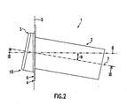
- the energy absorption device 1 is shown in a side view. From this representation it is particularly clear that the fastening plane 5 is aligned obliquely to the transverse direction of the hollow longitudinal section 2. That is, it extends obliquely to a line, not shown, perpendicular to the longitudinal axis 7 of the hollow longitudinal section 2 extending straight line. In other words, a normal 8 of the attachment plane 5 extends obliquely to the longitudinal axis 7 of the hollow longitudinal section 2.
- the hollow longitudinal section is aligned obliquely to the axial direction of the attachment section.
- the normal 8 runs in the axial direction of the attachment portion.
- the mounting plane and the transverse direction include an angle of about 5 ° to 20 °, preferably an angle of 8 ° to 12 °, and more preferably an angle of about 10 °.
- the normal 8 and the longitudinal axis 7 of the hollow longitudinal section 2 include an angle 9 of the size described above.
- FIG. 3 is a longitudinal sectional view of the energy absorption device according to the line III-III in FIG. 2 shown. It can be seen that the invaginated region 3 formed in an end region 10 of the energy absorption device has a purely U-shaped turn-up mold with a U-bend 17. From the outer U-section 11 of the invaginated area 3 goes directly into the mounting portion 4.
- the attachment portion 4 starts in the immediate vicinity of the hollow longitudinal portion 2. That is, the distance of the attachment portion 4 to the hollow longitudinal portion 2 is small compared to the cross-sectional width of the hollow longitudinal portion 2. In addition, the attachment portion is approximately in the direction of the hollow longitudinal portion at the level of the inverted area 3.
- the energy absorption device is stable and can be stored directly on a vehicle structure.
- an end 12 of the energy absorbing device opposite the inverted region 3 remains sufficiently movable to adapt to accident forces whose direction is oblique to the longitudinal axis 7 of the hollow longitudinal section.
- a pivoting of the hollow longitudinal portion 2 can be compensated, wherein in a peripheral portion of a stülpendes deformation of the hollow longitudinal portion can occur.
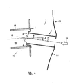
- FIG. 4 shows the energy absorbing device schematically in a arranged between a body structure 13 and a bumper arrangement 14 layer.
- the body structure 13 may be, for example, a longitudinal member whose longitudinal direction 15 is parallel to the vehicle longitudinal direction.
- the energy absorbing device 1 is fixed to the body structure 13 so that the normal 8 of the attachment plane 5 and the longitudinal direction 15 of the body structure are parallel to each other. In this embodiment of the invention, they even coincide. Accordingly, the fastening plane 5 is approximately perpendicular to the vehicle longitudinal direction aligned and the longitudinal axis 7 of the hollow longitudinal section 2 extends at an angle of said size obliquely to the vehicle longitudinal direction.
- the energy absorbing device is shown in an initial state prior to energy absorption. If an accident force 16 acts approximately in the direction of the longitudinal axis 7 of the hollow longitudinal section 2, the energy absorption device deforms plastically. In this case, the U-bend 17 of the invaginated area 3 is bent and always new material of the everting hollow hollow longitudinal section 2 forms a preceding arc.
- the hollow longitudinal section telescopes into a cavity 18 of the body structure 13. With advancing, energy absorbing telescoping inside the leading round comes into contact with a wall 19 of the body structure 13.
- the wall 19 serves the hollow longitudinal section as a support and guidance in further everting deformation.
- the hollow longitudinal section can roll over on the wall 19 umstülpend. Thus, a contact with the wall runs smoothly.
- the energy absorbing device can be made by a deep drawing method of a sheet, e.g. B. from a round blank.
- a part of the flat material is used to form the hollow longitudinal section 2 and the invaginated region 3.
- a part of the flat material remains flat and is used to form the attachment portion 4.
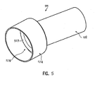
- FIG. 5 an energy absorption device 101 of a second embodiment of the invention is shown in a perspective view, in FIG. 6 in a plan view and in FIG. 7 in a longitudinal sectional view according to FIG. 6 ,
- the energy absorbing device 101 has a first hollow longitudinal portion 102 having a first cross-sectional width 103 and a second hollow longitudinal portion 104 having a second cross-sectional width 105.
- the first cross-sectional width 103 is smaller than the second cross-sectional width 105.
- the first and second hollow longitudinal sections 102, 104 are tubular in this embodiment.
- other open or closed hollow body-like shapes are possible, for example, with a polygonal cross-sectional shape.
- an inverted transition region 106 is formed.
- a turned-up region which is connected to a continuation section, adjoins a hollow longitudinal section intended for reshaping.
- the first hollow longitudinal section or the second hollow longitudinal section may be the continuation section.
- the inverted transition region has a substantially S-shaped or double-U-shaped longitudinal section profile, as seen from FIG. 7 evident.
- a first U-bend 107 starts from the first hollow longitudinal profile 102 and is arranged within the second hollow longitudinal section 104.
- a second U-bend 108 starts from the second hollow longitudinal profile 104 and is arranged outside the first hollow longitudinal section 102 and surrounds the same.
- the first hollow longitudinal section 102 and the second hollow longitudinal section 104 are aligned obliquely with each other, their longitudinal axes 109, 110 forming an angle 111 with one another.
- the angle 111 is selected in the range of about 5 to 20 °, preferably in the range of about 8 to 12 °, and more preferably in the range of about 10 °.
- the energy absorbing device is integrally formed.
- FIG. 4 illustrates how the energy absorbing device 101 may be disposed in a vehicle. In the present embodiment, it is provided between a body structure 112 and a bumper assembly 113. The illustration is in FIG. 8 a schematic view of the longitudinal section profiles.
- the bumper assembly 113 may be a cross member or cross profile of a bumper, and the body structure 112 may be a side rail of a vehicle body.
- the second hollow longitudinal section of greater cross-sectional width is attached to the body structure 112 and its longitudinal axis 110 is parallel to the longitudinal axis 114 of the body structure 112, these two longitudinal axes 110, 114 coinciding in this embodiment of the invention.
- the longitudinal axis 114 of the body structure 112 extends parallel to the longitudinal direction of the vehicle.
- the first hollow longitudinal section 102 of smaller cross-sectional width is arranged running obliquely to the vehicle longitudinal direction.
- the longitudinal axis 109 of the first hollow longitudinal section consequently includes the same angle with the vehicle longitudinal direction as with the longitudinal axis 110 of the second hollow longitudinal section 104.
- Embodiments are also possible in which the longitudinal axis of the hollow longitudinal section of lesser cross-sectional width runs parallel to the longitudinal axis of the body structure and is fastened thereto.
- the hollow longitudinal section of larger cross-sectional width would then be arranged running obliquely to the vehicle longitudinal direction.
- the first hollow longitudinal section arranged on the bumper side has a higher slip-over capability than the second hollow longitudinal section arranged on the body side.
- the energy absorbing deformation of the energy absorbing device 101 is substantially at the expense of the first hollow longitudinal portion 102. That is, in this embodiment of the invention, the second hollow longitudinal portion is the continuation portion.
- FIG. 9 is the energy absorption device 101 in the initial state before the absorption of the accident energy, ie in the state as in the FIGS. 5 to 8 is shown.
- the first hollow longitudinal section 102 begins to plastically deform from the first U-bend 107.
- a deviation of the direction of the accident force 115 from the direction of the longitudinal axis 109 of the first hollow longitudinal section 102 is compensated by the quasi loose storage of the transition region and by a bulging deformation, which initially takes place only in a peripheral portion.
- the first U-bend 107 of the transition region 106 is bent and always new material of the first hollow longitudinal portion 102 now forms a preceding arc 170. This reaches the inside of the second hollow longitudinal portion 104.
- the second hollow longitudinal portion 104 forms a guide of the first Hollow longitudinal section 102.
- the first hollow longitudinal section is supported on the second hollow longitudinal section and rolls on this from, as shown in the Figures 10 and 11 is shown.
- the accident force received by the obliquely oriented first hollow longitudinal section 102 is still relatively straightly introduced into the body structure 112 by the second hollow longitudinal section. With its larger cross-sectional width 105, the second hollow longitudinal section 104 is well stabilized.
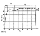
- FIG. 12 is a Kraftwegdiagramm for the energy absorption device according to the invention shown.
- a first path section 120 includes the Hook's region. With the transition to a second path section 121, the plastic deformation of the energy absorption device begins. In the course of the second path section 121 of the effort increases in sections, and then falls off slightly afterwards. This increased force is required for the bending of the original first U-bend 107.
- FIG. 13 there is shown a tube 130 of first cross-sectional width 103 used in a first embodiment of the manufacturing method according to the invention.
- an Innhoch horrumformungs vide the cross-sectional width of the tube 130 is enlarged in sections.
- a longitudinally section approximately conical transition region 131 is formed between the resulting hollow longitudinal sections 102, 104, as in FIG. 14 is shown.
- the two hollow longitudinal sections 102, 104 are now pressed in the longitudinal direction to each other, that is, the conical transition region 131 is compressed, resulting in an S or double-U-shaped transition region. Subsequently, the hollow longitudinal portions 102, 104 are brought with a tool in an angular alignment with each other, wherein the transition region plastically deformed and in the FIGS. 5 to 7 takes form shown.
- FIGS. 15 and 16 a second embodiment of the manufacturing method according to the invention is illustrated.
- a tube 140 is used, as in FIG. 13 shown, but has a larger cross-sectional width.
- the tube 140 is clamped between axial bearings or brackets 142, 143.
- the cross-sectional width of the tube 140 is partially narrowed.
- a transition region 141 is formed, which initially has an approximately wedge-shaped profile in longitudinal section.
- the length of the tube 140 would extend without the axial bearing 142, 143.
- the axial bearings 142, 143 force the tube 140 to maintain its axial length, the transition region 141 is deformed in an inverted manner.
- forming an S- or double-U-shaped transition region in this manufacturing process is an integrated process.
- the resulting hollow longitudinal portions 102, 104 are aligned with the aid of a tool at an angle to each other, wherein the transition region plastically deformed and in the FIGS. 5 to 7 takes form shown.
- the transition region 141 is compressed after rolling as in the first embodiment of the manufacturing process.
- the second U-bend 108 that is to say the U-bend adjoining the second hollow longitudinal section 104 not provided for everting deformation, can be stabilized by a joining method. This counteracts deformation at the expense of the second hollow longitudinal section.
- a joining material adhesive welding material or soldering material can be used, which is introduced into this U-bend 108.
- Joining stabilization has a similar effect as good work hardening or providing profiling in the second U-bend. These measures can be taken additionally or alternatively.
- the solidification measures can also be made on the first U-bend 107 when the second hollow longitudinal section is provided for everting deformation.
- the energy absorbing device may be made of, for example, steels with induced plasticity. You will experience a significant increase in stretchability with greater strength during forming. In this way, the energy absorbing device can also be made by rolling under narrowing of the cross-sectional width, wherein the area of narrowed cross-sectional, d. H. the first hollow longitudinal section remains the inverted cross-sectional section, although its strength increases somewhat as a result of the deformation.
- induced plasticity steels for example, light weight steels with induced plasticity (LIP) steels, extremely high strength steels with induced plasticity (STB) or twinning induced plasticity (TWIP) steels can be used.
- LIP light weight steels with induced plasticity
- STB extremely high strength steels with induced plasticity
- TWIP twinning induced plasticity
- the energy absorbing device of the first embodiment of the invention can be manufactured from the mentioned steels.
Landscapes
- Engineering & Computer Science (AREA)
- Mechanical Engineering (AREA)
- General Engineering & Computer Science (AREA)
- Vibration Dampers (AREA)
- Body Structure For Vehicles (AREA)
- Buildings Adapted To Withstand Abnormal External Influences (AREA)
Claims (17)
- Dispositif d'absorption d'énergie (1, 101) pour un dispositif d'amortissement des chocs d'un véhicule, avec un tronçon longitudinal creux (2, 102) qui est destiné à être déformé, une zone retournée (3, 106) qui fait suite au tronçon longitudinal creux, et un tronçon de prolongement (4, 104) qui est relié à la zone retournée,
caractérisé en ce que le tronçon longitudinal creux (2, 102), dans une position initiale avant une absorption d'énergie, est incliné par rapport au sens axial du tronçon de prolongement (4, 104). - Dispositif d'absorption d'énergie selon la revendication 1, caractérisé en ce que le sens axial du tronçon longitudinal creux (2, 102) ou du tronçon de prolongement (4, 104) est incliné par rapport à un sens longitudinal du véhicule, et le sens axial de l'autre tronçon est globalement parallèle au sens longitudinal du véhicule.
- Dispositif d'absorption d'énergie selon la revendication 1 ou 2, caractérisé en ce que le tronçon longitudinal creux (2, 102) est incliné d'environ 5° à 20° par rapport au sens axial du tronçon de prolongement (4, 104), de préférence d'environ 8° à 12°, plus spécialement d'environ 10°.
- Dispositif d'absorption d'énergie selon l'une au moins des revendications précédentes, caractérisé en ce qu'il est prévu un guide (19, 104) sur lequel le tronçon longitudinal creux (2, 102) roule lors de la déformation.
- Dispositif d'absorption d'énergie (1) selon l'une au moins des revendications précédentes, étant précisé que le tronçon longitudinal creux (2) destiné à être déformé est incliné par rapport au sens longitudinal du véhicule et qu'il est prévu comme tronçon de prolongement un tronçon de fixation (4) du dispositif d'absorption d'énergie qui définit un plan de fixation (5) du dispositif d'absorption d'énergie,
caractérisé en ce que le plan de fixation (5), dans un état initial avant une absorption d'énergie, est incliné par rapport au sens transversal du tronçon longitudinal creux (2). - Dispositif d'absorption d'énergie selon la revendication 5, caractérisé en ce que le plan de fixation (5) est à peu près perpendiculaire au sens longitudinal du véhicule.
- Dispositif d'absorption d'énergie selon l'une au moins des revendications précédentes, caractérisé en ce que la zone retournée (3) est formée sur une zone d'extrémité (10) du dispositif d'absorption d'énergie.
- Dispositif d'absorption d'énergie selon l'une au moins des revendications précédentes, caractérisé en ce qu'il est apte à être fixé à une structure de carrosserie (13) à peu près à la hauteur de la zone retournée (3), dans le sens du tronçon longitudinal creux (2).
- Dispositif d'absorption d'énergie selon l'une au moins des revendications précédentes, caractérisé en ce que la zone retournée (3) a une forme retournée seulement en U.
- Dispositif d'absorption d'énergie selon l'une au moins des revendications 5 à 9, caractérisé en ce que le tronçon de fixation (4) a la forme d'une bride, d'un rebord ou d'une collerette.
- Structure de véhicule avec un dispositif d'absorption d'énergie selon l'une au moins des revendications précédentes, caractérisée en ce qu'elle présente une paroi (19) qui forme un guide du tronçon longitudinal creux (2) sur lequel ce dernier est apte à rouler lors de la déformation.
- Dispositif d'absorption d'énergie (101) selon l'une au moins des revendications 1 à 4, avec un premier tronçon longitudinal creux (102) présentant une première largeur de section transversale (103), et un second tronçon longitudinal creux (104) présentant une seconde largeur de section transversale (105), et comme zone retournée un
tronçon de transition retourné (106) entre les tronçons longitudinaux creux,
caractérisé en ce que le premier tronçon longitudinal creux (102) et le second tronçon longitudinal creux (104), dans un état initial avant une absorption d'énergie, sont inclinés l'un par rapport à l'autre. - Dispositif d'absorption d'énergie selon la revendication 12, caractérisé en ce que le tronçon creux le plus apte à être retourné (102) est incliné par rapport au sens longitudinal du véhicule.
- Dispositif d'absorption d'énergie selon la revendication 12 ou 13, caractérisé en ce que le tronçon longitudinal creux (102) de plus petite largeur de section transversale (103) est plus apte à être retourné que le tronçon longitudinal creux (104) de plus grande largeur de section transversale (105).
- Dispositif d'absorption d'énergie selon la revendication 14, caractérisé en ce que le tronçon longitudinal creux (104) de plus grande largeur de section transversale (105) forme un guide du tronçon longitudinal creux (102) de plus petite largeur de section transversale (103).
- Procédé pour fabriquer un dispositif d'absorption d'énergie (101) d'une seule pièce qui comporte un premier tronçon longitudinal creux (102) présentant une première largeur de section transversale (103), et un second tronçon longitudinal creux (104) présentant une seconde largeur de section transversale (105), ainsi qu'une zone de transition retournée (106) entre les deux tronçons longitudinaux creux, le procédé ayant les étapes suivantes :modification locale de la largeur de section transversale d'un tube (130, 140) présentant une première largeur de section transversale jusqu'à obtention de la seconde largeur de section transversale, en formant les tronçons longitudinaux creux (102, 104) présentant les première et seconde largeurs de section transversale (103, 105), et écrasement du tube (130, 140), moyennant quoi la zone de transmission retournée (106) est formée,caractérisé en ce que les tronçons longitudinaux creux (102, 104) sont inclinés l'un par rapport à l'autre.
- Procédé selon la revendication 16, caractérisé en ce que le tube (130) présentant la première largeur de section transversale (103) est agrandi localement par déformation par haute pression interne jusqu'à obtention de la seconde largeur de section transversale (105).
Applications Claiming Priority (3)
| Application Number | Priority Date | Filing Date | Title |
|---|---|---|---|
| DE200620018616 DE202006018616U1 (de) | 2006-12-08 | 2006-12-08 | Energieabsorptionsvorrichtung |
| DE200610057993 DE102006057993A1 (de) | 2006-12-08 | 2006-12-08 | Energieabsorptionsvorrichtung |
| PCT/EP2007/010386 WO2008067951A1 (fr) | 2006-12-08 | 2007-11-29 | Dispositif d'absorption d'énergie |
Publications (2)
| Publication Number | Publication Date |
|---|---|
| EP2091787A1 EP2091787A1 (fr) | 2009-08-26 |
| EP2091787B1 true EP2091787B1 (fr) | 2011-03-09 |
Family
ID=39146885
Family Applications (1)
| Application Number | Title | Priority Date | Filing Date |
|---|---|---|---|
| EP07846911A Not-in-force EP2091787B1 (fr) | 2006-12-08 | 2007-11-29 | Dispositif d'absorption d'énergie |
Country Status (9)
| Country | Link |
|---|---|
| US (1) | US8070197B2 (fr) |
| EP (1) | EP2091787B1 (fr) |
| JP (1) | JP2010511555A (fr) |
| KR (1) | KR20090088439A (fr) |
| AT (1) | ATE501000T1 (fr) |
| CA (1) | CA2671986A1 (fr) |
| DE (1) | DE502007006696D1 (fr) |
| RU (1) | RU2444656C2 (fr) |
| WO (1) | WO2008067951A1 (fr) |
Families Citing this family (7)
| Publication number | Priority date | Publication date | Assignee | Title |
|---|---|---|---|---|
| GB0904343D0 (en) * | 2009-03-13 | 2009-04-29 | Linde Ag | Vehicle structures |
| ES2409118T3 (es) * | 2009-06-08 | 2013-06-25 | Faurecia Exteriors Gmbh | Elemento de absorción de energía para sistemas de gestión de choques en automóviles |
| JP5507971B2 (ja) * | 2009-11-16 | 2014-05-28 | アイシン精機株式会社 | 衝撃吸収具及び車両用バンパ装置 |
| DE102012103426B4 (de) * | 2012-04-19 | 2018-03-08 | Deutsches Zentrum für Luft- und Raumfahrt e.V. | Energieabsorptionsvorrichtung und Fahrzeug |
| DE102014108979B4 (de) * | 2014-06-26 | 2019-10-17 | Thyssenkrupp Steel Europe Ag | Vorrichtung zur Absorption von Energie bei einem Fahrzeugaufprall |
| FR3038573A1 (fr) * | 2015-07-06 | 2017-01-13 | Peugeot Citroen Automobiles Sa | Structure arriere de vehicule pour choc urbain |
| US9457746B1 (en) * | 2015-11-09 | 2016-10-04 | Ford Global Technologies, Llc | Energy absorbing system for vehicular impacts |
Family Cites Families (13)
| Publication number | Priority date | Publication date | Assignee | Title |
|---|---|---|---|---|
| US3912295A (en) * | 1974-03-04 | 1975-10-14 | Budd Co | Crash energy-attenuating means for a vehicle frame construction |
| SU968535A1 (ru) * | 1981-03-03 | 1982-10-23 | Ростовское Высшее Военное Командное Училище Им.Главного Маршала Артиллерии Неделина М.И. | Пластический амортизатор |
| JP3380537B2 (ja) * | 1999-09-02 | 2003-02-24 | オーエム工業株式会社 | 車輌の衝撃吸収装置 |
| DE10042221A1 (de) | 1999-09-02 | 2001-08-09 | Om Corp | Stoßdämpfer für ein Fahrzeug, das plastische Verformungen ausnutzt |
| JP2002331888A (ja) | 2001-05-10 | 2002-11-19 | Om Kogyo Kk | バンパ取付構造 |
| US7070217B2 (en) * | 2002-04-19 | 2006-07-04 | Magna International Inc. | Collision energy-absorbing device |
| JP2004042883A (ja) * | 2002-05-14 | 2004-02-12 | Aisin Seiki Co Ltd | バンパ装置 |
| US6854574B2 (en) | 2002-05-29 | 2005-02-15 | Asteer Co., Ltd. | Shock absorber |
| JP4257128B2 (ja) * | 2003-02-03 | 2009-04-22 | 株式会社アステア | 衝撃吸収装置 |
| JP4219189B2 (ja) * | 2003-02-28 | 2009-02-04 | 株式会社アステア | 車体メンバに対するバンパ補強材の支持構造 |
| EP1714834A1 (fr) | 2004-02-10 | 2006-10-25 | Sango Co., Ltd. | Dispositif d absorption des chocs pour un vehicule |
| JP2006008088A (ja) * | 2004-06-22 | 2006-01-12 | Sango Co Ltd | 車両の衝撃吸収装置 |
| JP4795713B2 (ja) * | 2005-04-22 | 2011-10-19 | フタバ産業株式会社 | 衝撃吸収装置 |
-
2007
- 2007-11-27 US US12/517,827 patent/US8070197B2/en not_active Expired - Fee Related
- 2007-11-29 WO PCT/EP2007/010386 patent/WO2008067951A1/fr not_active Ceased
- 2007-11-29 AT AT07846911T patent/ATE501000T1/de active
- 2007-11-29 DE DE502007006696T patent/DE502007006696D1/de active Active
- 2007-11-29 RU RU2009125698/11A patent/RU2444656C2/ru not_active IP Right Cessation
- 2007-11-29 KR KR1020097014197A patent/KR20090088439A/ko not_active Ceased
- 2007-11-29 JP JP2009539645A patent/JP2010511555A/ja active Pending
- 2007-11-29 EP EP07846911A patent/EP2091787B1/fr not_active Not-in-force
- 2007-11-29 CA CA002671986A patent/CA2671986A1/fr not_active Abandoned
Also Published As
| Publication number | Publication date |
|---|---|
| US8070197B2 (en) | 2011-12-06 |
| CA2671986A1 (fr) | 2008-06-12 |
| RU2009125698A (ru) | 2011-01-20 |
| KR20090088439A (ko) | 2009-08-19 |
| JP2010511555A (ja) | 2010-04-15 |
| EP2091787A1 (fr) | 2009-08-26 |
| US20100320782A1 (en) | 2010-12-23 |
| WO2008067951A1 (fr) | 2008-06-12 |
| ATE501000T1 (de) | 2011-03-15 |
| RU2444656C2 (ru) | 2012-03-10 |
| WO2008067951A8 (fr) | 2010-03-04 |
| DE502007006696D1 (de) | 2011-04-21 |
Similar Documents
| Publication | Publication Date | Title |
|---|---|---|
| EP2773549B1 (fr) | Châssis auxiliaire muni de moulures | |
| EP2091787B1 (fr) | Dispositif d'absorption d'énergie | |
| EP3530497B1 (fr) | Composant de châssis à butée disque excentrique ainsi que procédé de fabrication d'un composant de châssis | |
| EP2477765B1 (fr) | Méthode de fabrication d'un bras oscillant pour véhicule | |
| DE10326554B4 (de) | Verfahren zum Herstellen einer Stossstangenverstärkung | |
| EP2910454B1 (fr) | Composant de châssis avec butée de disque d'excentrique | |
| DE102015209060B4 (de) | Lenksäule für ein Kraftfahrzeug und Energieabsorptionseinrichtung | |
| DE102009031981B4 (de) | Verfahren zur Herstellung eines Kraftfahrzeugbauteils in Form eines Torsionsprofils | |
| EP3475589B1 (fr) | Système d'articulation, module préfabriqué et procédé de fabrication d'un module préfabriqué d'un système d'articulation | |
| DE19756459A1 (de) | Aufprallträger für eine Kraftfahrzeugtür | |
| DE102007038713B4 (de) | Verfahren zur Herstellung von partiell verstärkten Hohlprofilen | |
| DE10135063B4 (de) | Luftfedertopf sowie Verfahren zur Herstellung desselben | |
| DE202007018727U1 (de) | Abschleppbuchseneinheit | |
| DE102013107179B4 (de) | Stoßabsorptionsvorrichtung für ein Kraftfahrzeug | |
| DE102009011378A1 (de) | Türaufprallträger | |
| DE102007056645B4 (de) | Schweller eines Kraftfahrzeugs und Kraftfahrzeug | |
| DE102008000936A1 (de) | Radaufhängung für ein Fahrzeug und Verbindungselement für eine solche Radaufhängung | |
| DE10130794A1 (de) | Strukturteil eines Kraftfahrzeugkörpers und Verfahren zu dessen Herstellung | |
| EP1828551A1 (fr) | Cames destinees a des arbres a cames fabriques | |
| DE102015204917A1 (de) | Seitentür für ein Fahrzeug sowie Fahrzeug mit einer derartigen Seitentür | |
| DE102005035478B4 (de) | Verfahren und Werkzeug zur Herstellung eines Flansches an einem Buchsenlager | |
| DE102005026444B4 (de) | Energieabsorptionsvorrichtung und Verfahren zum Herstellen einer einstückigen Energieabsorptionsvorrichtung | |
| EP0648985A2 (fr) | Absorbeur solaire et méthode pour sa fabrication | |
| EP2330307A1 (fr) | Elément de support pour palier et son procédé de fabrication | |
| DE102006057993A1 (de) | Energieabsorptionsvorrichtung |
Legal Events
| Date | Code | Title | Description |
|---|---|---|---|
| PUAI | Public reference made under article 153(3) epc to a published international application that has entered the european phase |
Free format text: ORIGINAL CODE: 0009012 |
|
| 17P | Request for examination filed |
Effective date: 20090608 |
|
| AK | Designated contracting states |
Kind code of ref document: A1 Designated state(s): AT BE BG CH CY CZ DE DK EE ES FI FR GB GR HU IE IS IT LI LT LU LV MC MT NL PL PT RO SE SI SK TR |
|
| 17Q | First examination report despatched |
Effective date: 20091210 |
|
| DAX | Request for extension of the european patent (deleted) | ||
| GRAP | Despatch of communication of intention to grant a patent |
Free format text: ORIGINAL CODE: EPIDOSNIGR1 |
|
| GRAS | Grant fee paid |
Free format text: ORIGINAL CODE: EPIDOSNIGR3 |
|
| GRAA | (expected) grant |
Free format text: ORIGINAL CODE: 0009210 |
|
| AK | Designated contracting states |
Kind code of ref document: B1 Designated state(s): AT BE BG CH CY CZ DE DK EE ES FI FR GB GR HU IE IS IT LI LT LU LV MC MT NL PL PT RO SE SI SK TR |
|
| REG | Reference to a national code |
Ref country code: GB Ref legal event code: FG4D Free format text: NOT ENGLISH |
|
| REG | Reference to a national code |
Ref country code: CH Ref legal event code: EP |
|
| REG | Reference to a national code |
Ref country code: IE Ref legal event code: FG4D Free format text: LANGUAGE OF EP DOCUMENT: GERMAN |
|
| REF | Corresponds to: |
Ref document number: 502007006696 Country of ref document: DE Date of ref document: 20110421 Kind code of ref document: P |
|
| REG | Reference to a national code |
Ref country code: DE Ref legal event code: R096 Ref document number: 502007006696 Country of ref document: DE Effective date: 20110421 |
|
| REG | Reference to a national code |
Ref country code: SE Ref legal event code: TRGR |
|
| REG | Reference to a national code |
Ref country code: ES Ref legal event code: FG2A Ref document number: 2360928 Country of ref document: ES Kind code of ref document: T3 Effective date: 20110610 |
|
| REG | Reference to a national code |
Ref country code: NL Ref legal event code: VDEP Effective date: 20110309 |
|
| PG25 | Lapsed in a contracting state [announced via postgrant information from national office to epo] |
Ref country code: LV Free format text: LAPSE BECAUSE OF FAILURE TO SUBMIT A TRANSLATION OF THE DESCRIPTION OR TO PAY THE FEE WITHIN THE PRESCRIBED TIME-LIMIT Effective date: 20110309 Ref country code: LT Free format text: LAPSE BECAUSE OF FAILURE TO SUBMIT A TRANSLATION OF THE DESCRIPTION OR TO PAY THE FEE WITHIN THE PRESCRIBED TIME-LIMIT Effective date: 20110309 Ref country code: GR Free format text: LAPSE BECAUSE OF FAILURE TO SUBMIT A TRANSLATION OF THE DESCRIPTION OR TO PAY THE FEE WITHIN THE PRESCRIBED TIME-LIMIT Effective date: 20110610 |
|
| REG | Reference to a national code |
Ref country code: SK Ref legal event code: T3 Ref document number: E 9449 Country of ref document: SK |
|
| LTIE | Lt: invalidation of european patent or patent extension |
Effective date: 20110309 |
|
| PG25 | Lapsed in a contracting state [announced via postgrant information from national office to epo] |
Ref country code: BG Free format text: LAPSE BECAUSE OF FAILURE TO SUBMIT A TRANSLATION OF THE DESCRIPTION OR TO PAY THE FEE WITHIN THE PRESCRIBED TIME-LIMIT Effective date: 20110609 Ref country code: FI Free format text: LAPSE BECAUSE OF FAILURE TO SUBMIT A TRANSLATION OF THE DESCRIPTION OR TO PAY THE FEE WITHIN THE PRESCRIBED TIME-LIMIT Effective date: 20110309 Ref country code: SI Free format text: LAPSE BECAUSE OF FAILURE TO SUBMIT A TRANSLATION OF THE DESCRIPTION OR TO PAY THE FEE WITHIN THE PRESCRIBED TIME-LIMIT Effective date: 20110309 Ref country code: NL Free format text: LAPSE BECAUSE OF FAILURE TO SUBMIT A TRANSLATION OF THE DESCRIPTION OR TO PAY THE FEE WITHIN THE PRESCRIBED TIME-LIMIT Effective date: 20110309 Ref country code: CY Free format text: LAPSE BECAUSE OF FAILURE TO SUBMIT A TRANSLATION OF THE DESCRIPTION OR TO PAY THE FEE WITHIN THE PRESCRIBED TIME-LIMIT Effective date: 20110309 |
|
| REG | Reference to a national code |
Ref country code: IE Ref legal event code: FD4D |
|
| PG25 | Lapsed in a contracting state [announced via postgrant information from national office to epo] |
Ref country code: PT Free format text: LAPSE BECAUSE OF FAILURE TO SUBMIT A TRANSLATION OF THE DESCRIPTION OR TO PAY THE FEE WITHIN THE PRESCRIBED TIME-LIMIT Effective date: 20110711 Ref country code: EE Free format text: LAPSE BECAUSE OF FAILURE TO SUBMIT A TRANSLATION OF THE DESCRIPTION OR TO PAY THE FEE WITHIN THE PRESCRIBED TIME-LIMIT Effective date: 20110309 Ref country code: IE Free format text: LAPSE BECAUSE OF FAILURE TO SUBMIT A TRANSLATION OF THE DESCRIPTION OR TO PAY THE FEE WITHIN THE PRESCRIBED TIME-LIMIT Effective date: 20110309 |
|
| PG25 | Lapsed in a contracting state [announced via postgrant information from national office to epo] |
Ref country code: RO Free format text: LAPSE BECAUSE OF FAILURE TO SUBMIT A TRANSLATION OF THE DESCRIPTION OR TO PAY THE FEE WITHIN THE PRESCRIBED TIME-LIMIT Effective date: 20110309 Ref country code: IS Free format text: LAPSE BECAUSE OF FAILURE TO SUBMIT A TRANSLATION OF THE DESCRIPTION OR TO PAY THE FEE WITHIN THE PRESCRIBED TIME-LIMIT Effective date: 20110709 |
|
| PLBE | No opposition filed within time limit |
Free format text: ORIGINAL CODE: 0009261 |
|
| STAA | Information on the status of an ep patent application or granted ep patent |
Free format text: STATUS: NO OPPOSITION FILED WITHIN TIME LIMIT |
|
| 26N | No opposition filed |
Effective date: 20111212 |
|
| PG25 | Lapsed in a contracting state [announced via postgrant information from national office to epo] |
Ref country code: PL Free format text: LAPSE BECAUSE OF FAILURE TO SUBMIT A TRANSLATION OF THE DESCRIPTION OR TO PAY THE FEE WITHIN THE PRESCRIBED TIME-LIMIT Effective date: 20110309 Ref country code: DK Free format text: LAPSE BECAUSE OF FAILURE TO SUBMIT A TRANSLATION OF THE DESCRIPTION OR TO PAY THE FEE WITHIN THE PRESCRIBED TIME-LIMIT Effective date: 20110309 |
|
| REG | Reference to a national code |
Ref country code: DE Ref legal event code: R097 Ref document number: 502007006696 Country of ref document: DE Effective date: 20111212 |
|
| BERE | Be: lapsed |
Owner name: COSMA ENGINEERING EUROPE AG Effective date: 20111130 |
|
| PG25 | Lapsed in a contracting state [announced via postgrant information from national office to epo] |
Ref country code: MC Free format text: LAPSE BECAUSE OF NON-PAYMENT OF DUE FEES Effective date: 20111130 |
|
| REG | Reference to a national code |
Ref country code: CH Ref legal event code: PL |
|
| PG25 | Lapsed in a contracting state [announced via postgrant information from national office to epo] |
Ref country code: CH Free format text: LAPSE BECAUSE OF NON-PAYMENT OF DUE FEES Effective date: 20111130 Ref country code: LI Free format text: LAPSE BECAUSE OF NON-PAYMENT OF DUE FEES Effective date: 20111130 |
|
| PG25 | Lapsed in a contracting state [announced via postgrant information from national office to epo] |
Ref country code: BE Free format text: LAPSE BECAUSE OF NON-PAYMENT OF DUE FEES Effective date: 20111130 |
|
| PG25 | Lapsed in a contracting state [announced via postgrant information from national office to epo] |
Ref country code: MT Free format text: LAPSE BECAUSE OF FAILURE TO SUBMIT A TRANSLATION OF THE DESCRIPTION OR TO PAY THE FEE WITHIN THE PRESCRIBED TIME-LIMIT Effective date: 20110309 |
|
| PGFP | Annual fee paid to national office [announced via postgrant information from national office to epo] |
Ref country code: AT Payment date: 20121029 Year of fee payment: 6 |
|
| PG25 | Lapsed in a contracting state [announced via postgrant information from national office to epo] |
Ref country code: LU Free format text: LAPSE BECAUSE OF NON-PAYMENT OF DUE FEES Effective date: 20111129 |
|
| PG25 | Lapsed in a contracting state [announced via postgrant information from national office to epo] |
Ref country code: TR Free format text: LAPSE BECAUSE OF FAILURE TO SUBMIT A TRANSLATION OF THE DESCRIPTION OR TO PAY THE FEE WITHIN THE PRESCRIBED TIME-LIMIT Effective date: 20110309 |
|
| PG25 | Lapsed in a contracting state [announced via postgrant information from national office to epo] |
Ref country code: HU Free format text: LAPSE BECAUSE OF FAILURE TO SUBMIT A TRANSLATION OF THE DESCRIPTION OR TO PAY THE FEE WITHIN THE PRESCRIBED TIME-LIMIT Effective date: 20110309 |
|
| PGFP | Annual fee paid to national office [announced via postgrant information from national office to epo] |
Ref country code: GB Payment date: 20131127 Year of fee payment: 7 Ref country code: SK Payment date: 20131104 Year of fee payment: 7 Ref country code: FR Payment date: 20131108 Year of fee payment: 7 Ref country code: CZ Payment date: 20131118 Year of fee payment: 7 Ref country code: DE Payment date: 20131127 Year of fee payment: 7 Ref country code: SE Payment date: 20131112 Year of fee payment: 7 |
|
| PGFP | Annual fee paid to national office [announced via postgrant information from national office to epo] |
Ref country code: IT Payment date: 20131115 Year of fee payment: 7 Ref country code: ES Payment date: 20131011 Year of fee payment: 7 |
|
| REG | Reference to a national code |
Ref country code: AT Ref legal event code: MM01 Ref document number: 501000 Country of ref document: AT Kind code of ref document: T Effective date: 20131129 |
|
| PG25 | Lapsed in a contracting state [announced via postgrant information from national office to epo] |
Ref country code: AT Free format text: LAPSE BECAUSE OF NON-PAYMENT OF DUE FEES Effective date: 20131129 |
|
| REG | Reference to a national code |
Ref country code: DE Ref legal event code: R119 Ref document number: 502007006696 Country of ref document: DE |
|
| REG | Reference to a national code |
Ref country code: SE Ref legal event code: EUG |
|
| GBPC | Gb: european patent ceased through non-payment of renewal fee |
Effective date: 20141129 |
|
| PG25 | Lapsed in a contracting state [announced via postgrant information from national office to epo] |
Ref country code: SK Free format text: LAPSE BECAUSE OF NON-PAYMENT OF DUE FEES Effective date: 20141129 Ref country code: CZ Free format text: LAPSE BECAUSE OF NON-PAYMENT OF DUE FEES Effective date: 20141129 Ref country code: SE Free format text: LAPSE BECAUSE OF NON-PAYMENT OF DUE FEES Effective date: 20141130 |
|
| REG | Reference to a national code |
Ref country code: SK Ref legal event code: MM4A Ref document number: E 9449 Country of ref document: SK Effective date: 20141129 |
|
| REG | Reference to a national code |
Ref country code: FR Ref legal event code: ST Effective date: 20150731 |
|
| PG25 | Lapsed in a contracting state [announced via postgrant information from national office to epo] |
Ref country code: DE Free format text: LAPSE BECAUSE OF NON-PAYMENT OF DUE FEES Effective date: 20150602 Ref country code: GB Free format text: LAPSE BECAUSE OF NON-PAYMENT OF DUE FEES Effective date: 20141129 |
|
| PG25 | Lapsed in a contracting state [announced via postgrant information from national office to epo] |
Ref country code: FR Free format text: LAPSE BECAUSE OF NON-PAYMENT OF DUE FEES Effective date: 20141201 |
|
| REG | Reference to a national code |
Ref country code: ES Ref legal event code: FD2A Effective date: 20151229 |
|
| PG25 | Lapsed in a contracting state [announced via postgrant information from national office to epo] |
Ref country code: IT Free format text: LAPSE BECAUSE OF NON-PAYMENT OF DUE FEES Effective date: 20141129 |
|
| PG25 | Lapsed in a contracting state [announced via postgrant information from national office to epo] |
Ref country code: ES Free format text: LAPSE BECAUSE OF NON-PAYMENT OF DUE FEES Effective date: 20141130 |