EP2092165B1 - Verwendung eines turboladers und abwärmeumwandlungssystem - Google Patents
Verwendung eines turboladers und abwärmeumwandlungssystem Download PDFInfo
- Publication number
- EP2092165B1 EP2092165B1 EP07857258A EP07857258A EP2092165B1 EP 2092165 B1 EP2092165 B1 EP 2092165B1 EP 07857258 A EP07857258 A EP 07857258A EP 07857258 A EP07857258 A EP 07857258A EP 2092165 B1 EP2092165 B1 EP 2092165B1
- Authority
- EP
- European Patent Office
- Prior art keywords
- turbine
- waste heat
- evaporator
- working fluid
- turbocharger
- Prior art date
- Legal status (The legal status is an assumption and is not a legal conclusion. Google has not performed a legal analysis and makes no representation as to the accuracy of the status listed.)
- Revoked
Links
- 239000002918 waste heat Substances 0.000 title claims abstract description 34
- 238000006243 chemical reaction Methods 0.000 title claims description 3
- 239000012530 fluid Substances 0.000 claims abstract description 33
- 239000007789 gas Substances 0.000 claims abstract description 24
- XLYOFNOQVPJJNP-UHFFFAOYSA-N water Substances O XLYOFNOQVPJJNP-UHFFFAOYSA-N 0.000 claims abstract description 13
- 239000003507 refrigerant Substances 0.000 claims description 4
- 230000005611 electricity Effects 0.000 claims description 2
- 239000002360 explosive Substances 0.000 claims description 2
- 231100000252 nontoxic Toxicity 0.000 claims description 2
- 230000003000 nontoxic effect Effects 0.000 claims description 2
- 238000004064 recycling Methods 0.000 abstract description 4
- 239000007788 liquid Substances 0.000 abstract description 3
- 238000000034 method Methods 0.000 abstract description 3
- 238000002485 combustion reaction Methods 0.000 description 5
- 238000004519 manufacturing process Methods 0.000 description 5
- MSSNHSVIGIHOJA-UHFFFAOYSA-N pentafluoropropane Chemical compound FC(F)CC(F)(F)F MSSNHSVIGIHOJA-UHFFFAOYSA-N 0.000 description 4
- 230000006835 compression Effects 0.000 description 3
- 238000007906 compression Methods 0.000 description 3
- 239000012809 cooling fluid Substances 0.000 description 3
- 238000001704 evaporation Methods 0.000 description 2
- 230000008020 evaporation Effects 0.000 description 2
- 229910000831 Steel Inorganic materials 0.000 description 1
- 238000009835 boiling Methods 0.000 description 1
- 238000009833 condensation Methods 0.000 description 1
- 230000005494 condensation Effects 0.000 description 1
- 238000001816 cooling Methods 0.000 description 1
- 230000001419 dependent effect Effects 0.000 description 1
- 239000000284 extract Substances 0.000 description 1
- 239000002803 fossil fuel Substances 0.000 description 1
- 239000000446 fuel Substances 0.000 description 1
- 239000011521 glass Substances 0.000 description 1
- 230000001050 lubricating effect Effects 0.000 description 1
- 238000005461 lubrication Methods 0.000 description 1
- 239000000123 paper Substances 0.000 description 1
- 238000010248 power generation Methods 0.000 description 1
- 230000011218 segmentation Effects 0.000 description 1
- 239000010959 steel Substances 0.000 description 1
- 239000000126 substance Substances 0.000 description 1
- 238000004056 waste incineration Methods 0.000 description 1
Images

Classifications
-
- F—MECHANICAL ENGINEERING; LIGHTING; HEATING; WEAPONS; BLASTING
- F01—MACHINES OR ENGINES IN GENERAL; ENGINE PLANTS IN GENERAL; STEAM ENGINES
- F01K—STEAM ENGINE PLANTS; STEAM ACCUMULATORS; ENGINE PLANTS NOT OTHERWISE PROVIDED FOR; ENGINES USING SPECIAL WORKING FLUIDS OR CYCLES
- F01K25/00—Plants or engines characterised by use of special working fluids, not otherwise provided for; Plants operating in closed cycles and not otherwise provided for
- F01K25/08—Plants or engines characterised by use of special working fluids, not otherwise provided for; Plants operating in closed cycles and not otherwise provided for using special vapours
- F01K25/10—Plants or engines characterised by use of special working fluids, not otherwise provided for; Plants operating in closed cycles and not otherwise provided for using special vapours the vapours being cold, e.g. ammonia, carbon dioxide, ether
-
- F—MECHANICAL ENGINEERING; LIGHTING; HEATING; WEAPONS; BLASTING
- F02—COMBUSTION ENGINES; HOT-GAS OR COMBUSTION-PRODUCT ENGINE PLANTS
- F02B—INTERNAL-COMBUSTION PISTON ENGINES; COMBUSTION ENGINES IN GENERAL
- F02B37/00—Engines characterised by provision of pumps driven at least for part of the time by exhaust
- F02B37/04—Engines with exhaust drive and other drive of pumps, e.g. with exhaust-driven pump and mechanically-driven second pump
- F02B37/10—Engines with exhaust drive and other drive of pumps, e.g. with exhaust-driven pump and mechanically-driven second pump at least one pump being alternatively or simultaneously driven by exhaust and other drive, e.g. by pressurised fluid from a reservoir or an engine-driven pump
-
- F—MECHANICAL ENGINEERING; LIGHTING; HEATING; WEAPONS; BLASTING
- F02—COMBUSTION ENGINES; HOT-GAS OR COMBUSTION-PRODUCT ENGINE PLANTS
- F02B—INTERNAL-COMBUSTION PISTON ENGINES; COMBUSTION ENGINES IN GENERAL
- F02B39/00—Component parts, details, or accessories relating to, driven charging or scavenging pumps, not provided for in groups F02B33/00 - F02B37/00
- F02B39/02—Drives of pumps; Varying pump drive gear ratio
- F02B39/08—Non-mechanical drives, e.g. fluid drives having variable gear ratio
- F02B39/085—Non-mechanical drives, e.g. fluid drives having variable gear ratio the fluid drive using expansion of fluids other than exhaust gases, e.g. a Rankine cycle
-
- Y—GENERAL TAGGING OF NEW TECHNOLOGICAL DEVELOPMENTS; GENERAL TAGGING OF CROSS-SECTIONAL TECHNOLOGIES SPANNING OVER SEVERAL SECTIONS OF THE IPC; TECHNICAL SUBJECTS COVERED BY FORMER USPC CROSS-REFERENCE ART COLLECTIONS [XRACs] AND DIGESTS
- Y02—TECHNOLOGIES OR APPLICATIONS FOR MITIGATION OR ADAPTATION AGAINST CLIMATE CHANGE
- Y02T—CLIMATE CHANGE MITIGATION TECHNOLOGIES RELATED TO TRANSPORTATION
- Y02T10/00—Road transport of goods or passengers
- Y02T10/10—Internal combustion engine [ICE] based vehicles
- Y02T10/12—Improving ICE efficiencies
Definitions
- the invention relates to the field of waste heat conversion. It departs from a system for converting waste heat by means of a closed organic rankine cycle system as described in the preamble of claim 3.
- Industrial processes generally produce waste heat, e.g. by gas condensation or cooling fluids, or comprised in exhaust gases from chemical, glass, paper or steel production processes, from waste incineration processes, or from fuel combustion in internal combustion engines such as gas turbines or reciprocating engines. Such waste heat is commonly discharged to the atmosphere.
- a bottoming cycle is commonly used. Bottoming cycles usually require high exhaust temperatures, yet an example of a bottoming cycle which requires lower exhaust temperatures is the Organic Rankine Cycle (ORC).
- ORC produces shaft power from lower temperature waste heat sources by using an organic working fluid with a boiling temperature suited to the heat source.
- the patent US 6880344 describes a closed rankine cycle that can efficiently use waste heat from several sources in a reciprocating or gas turbine engine system.
- a prior-art centrifugal compressor is used as the turbine.
- the organic rankine cycle system is combined with a vapour compression cycle system with the turbine generator of the organic rankine cycle generating the power necessary to operate the motor of the refrigerant compressor of the vapour compression cycle.
- the latter is applied with its evaporator cooling the inlet air into a gas turbine, and the organic rankine cycle is applied to receive heat from a gas turbine exhaust to heat its evaporator.
- a common condenser is used for the organic rankine cycle and the vapour compression cycle, with a common organic working fluid or refrigerant R-245fa being circulated within both systems.
- an organic rankine cycle system is applied to an internal combustion engine to cool the fluids thereof, and the turbo charged air is cooled first by the organic rankine cycle system and then by an air conditioner prior to passing into the intake of the engine.
- waste heat sources of comparatively low quality which so far have been disregarded mainly for economical reasons as well as for a lack of suitable equipment, are exploited by a novel waste heat recycling procedure.
- a closed rankine cycle system is powered with waste heat that is provided e.g. in the form of a hot cooling fluid or a flow of residual heat gas having a comparatively low temperature of less than 350°C, eventually less than 250°C and in some circumstances even less than 200°C.
- a suitable working fluid is evaporated to a pressure of less than 8 bar and preferably less than 6 bar, and subsequently fed to a turbine for producing shaft power.
- the limited pressure of the working fluid in the rankine cycle system allows using standard equipment and piping instead of high pressure equipment and piping, and prevents the heat exchanger from being subject to restrictive safety regulations.
- the shaft power can be used to generate pressurized gases such as air, by means of a turbocharger originally developed for an internal combustion engine such as a diesel and/or gas engine in the 500 kW plus power range.
- a turbocharger originally developed for an internal combustion engine such as a diesel and/or gas engine in the 500 kW plus power range.
- the one-stage axial or radial turbines of these turbochargers are well suited to the thermodynamic conditions chosen and in addition, due to their proven design and lifecycle stability, compensate for the somewhat reduced thermodynamic efficiency.
- the compressor stage of the turbocharger can be removed from the shaft of the turbine and replaced by a generator for generating electricity.
- the working fluid is an organic, non-toxic, non-explosive refrigerant such as R-245fa, available e.g. from Honeywell Inc. as Honeywell HFC-245fa or Genetron® 245fa.
- R-245fa organic, non-toxic, non-explosive refrigerant
- a working fluid of this kind could be evaporated and heated to a temperature of approximately 60°C by means of waste heat at a temperature of less than 200°C, where in some circumstances even waste heat temperatures as low as 150°C for a residual heat gas or 120°C for a cooling fluid were sufficient.
- the turbine is a high-speed turbine rotating at a speed of more than 1.5 times a nominal AC network frequency of an electric power network.
- This directly driven high speed generator including a frequency converter allows for a highly efficient power generation and avoids the drawbacks of a gear box between the turbine and the generator.
- a turbine inlet casing with a segmented cross section and comprising several distinct flow channels for guiding the evaporated working fluid to the blades of the rotor of the turbine is provided.
- the segmentation allows a better operation of the turbine at part-load conditions.
- variable inlet guide vanes may be employed, which likewise enable the turbine to operate in a broader load range and at high efficiencies.
- An exemplary guide-vane system for an axial flow exhaust gas turbocharger is disclosed in the EP1264079 .
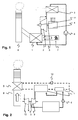
- Fig.1 shows a schematic illustration of a closed rankine cycle system, comprising, in a clockwise flow direction of the working fluid as indicated by the arrows, an evaporator 1 or boiler for the evaporation of a working fluid, a turbine 2 fed with vapour from the evaporator to drive, via a common shaft 3, a generator 4 connected to an electric power network or any other load, a separator 11, a condenser 5 for condensing the exhaust vapours from the turbine and means, such as a pump 6, for recycling the condensed working fluid to the evaporator 1.
- the separator 11 separates or extracts working fluid residues from the lubricating fluids such as oil used in the oil/lubrication system of the gearing of the turbine 2, and re-injects the separated working fluid residues into the main working fluid cycle as indicated by the dashed line.
- Residual heat gas or hot exhaust gas from the waste heat source 7 has a temperature, when entering the evaporator 1, which is below 350°C, and eventually below 250°C, at ambient pressure, and is finally released to the ambient via chimney 8.
- the working fluid is heated up to 60°C at a pressure of less than 8 bar and expanded in the turbine 2 to 30°C at ambient pressure, where it is still gaseous.
- Fig.2 depicts a system with an intermediate water circuit (dashed line).
- a water heat exchanger 9 is placed in the exhaust gas stream in chimney 8, where water is being heated up by heat from the residual gas.
- the water is conducted to evaporator 1, where the working fluid is evaporated and the steam condenses.
- the water is then cycled back to the water heat exchanger 9 by means of a water pump 10.
- evaporator 1 is a two-stage evaporator consisting of a liquid-liquid pre-heater and a gas-liquid evaporator, the two stages being serially traversed by the water and, in the opposite direction, by the working fluid.
- the turbine 2 is connected, via shaft 3, to a compressor instead of a generator, and the shaft power is used to generate pressurized gases.
- the rest of the working fluid cycle is unchanged with respect to Fig.1 .
Landscapes
- Engineering & Computer Science (AREA)
- Chemical & Material Sciences (AREA)
- Combustion & Propulsion (AREA)
- Mechanical Engineering (AREA)
- General Engineering & Computer Science (AREA)
- Engine Equipment That Uses Special Cycles (AREA)
- Processing Of Solid Wastes (AREA)
- Processing And Handling Of Plastics And Other Materials For Molding In General (AREA)
- Yarns And Mechanical Finishing Of Yarns Or Ropes (AREA)
- Spray-Type Burners (AREA)
- Thermotherapy And Cooling Therapy Devices (AREA)
- Central Heating Systems (AREA)
Claims (9)
- Verwendung eines Turboladers, der eine Turbine (2) aufweist, die über eine Welle (3) mit einer Kompressorstufe verbunden ist, um mit Druck beaufschlagte Gase zu erzeugen,
dadurch gekennzeichnet, dass die Turbine (2) des Turboladers mit einem System mit geschlossenem Rankine-Zyklus gekoppelt ist, das einen Verdampfer (1), die Turbine (2) des Turboladers und einen Kondensator (5) enthält, wobei der Verdampfer (1) durch Verlustwärme von einer Verlustwärmequelle (7) mit einer Verlustwärmetemperatur, die 350 °C und vorzugsweise 250 °C nicht übersteigt, erwärmt wird, wobei Arbeitsfluid in dem Verdampfer (1) verdampft wird, um die Turbine (2) bei einem Druck, der 8 Bar nicht übersteigt, anzutreiben und wobei der Kondensator (5) zwischen der Turbine (2) und dem Verdampfer (1) fluidtechnisch angeschlossen ist. - System, das Verlustwärme von einer Verlustwärmequelle (7) in Wellenleistung umsetzt, mit einem System mit geschlossenem Rankine-Zyklus, das einen durch die Verlustwärme erhitzten Verdampfer (1), eine Turbine (2), die durch ein im Verdampfer (1) verdampftes Arbeitsfluid angetrieben wird und mit einer Welle (3) verbunden ist, und einen Kondensator (5), der zwischen der Turbine (2) und dem Verdampfer (1) fluidtechnisch angeschlossen ist, enthält,
dadurch gekennzeichnet, dass eine Verlustwärmetemperatur im Verdampfer (1) 350 °C nicht übersteigt und vorzugsweise niedriger als 250 °C ist und dass ein Druck des verdampften Arbeitsfluids 8 Bar nicht übersteigt. - System nach Anspruch 2, dadurch gekennzeichnet, dass die Turbine (2) eine Turbine eines Turboladers ist, der über eine Welle (3) mit einem Generator (4) für die Erzeugung von Elektrizität verbunden ist.
- System nach Anspruch 2, dadurch gekennzeichnet, dass das Arbeitsfluid ein organisches, nicht toxisches, nicht explosives Kältemittel ist.
- System nach Anspruch 2, dadurch gekennzeichnet, dass Restwärme-Gase von der Verlustwärmequelle (7) über einen dazwischen angeordneten Wasser- oder Ölkreis in eine Wärmetauscherbeziehung mit dem Verdampfer (1) eintreten, um die Verlustwärme von dem Restwärmegas an das Arbeitsfluid zu übertragen.
- System nach Anspruch 2, dadurch gekennzeichnet, dass die Verlustwärme von der Verlustwärmequelle (7) das Arbeitsfluid in dem Verdampfer (1) ohne jegliches Zwischenfluid verdampft.
- System nach Anspruch 2, dadurch gekennzeichnet, dass die Turbine (2) eine Hochgeschwindigkeitsturbine mit einem einfachen Getriebe ist und sich mit einer Drehzahl dreht, die wenigstens gleich der 1,5-fachen Nennwechselstromfrequenz eines elektrischen Stromnetzes ist, und einen Hochgeschwindigkeitsgenerator, der Leistungselektronik für die Frequenzumsetzung enthält, versorgt.
- System nach Anspruch 2, dadurch gekennzeichnet, dass es einen Separator (11) zum Trennen von Arbeitsfluidresten von den in einem Ölsystem eines Getriebes der Turbine (2) verwendeten Fluiden enthält.
- System nach Anspruch 2, dadurch gekennzeichnet, dass die Turbine (2) ein segmentiertes Einlassgehäuse (13) oder eine variable Einlassführungsschaufel aufweist.
Priority Applications (3)
| Application Number | Priority Date | Filing Date | Title |
|---|---|---|---|
| EP10160319A EP2211028B1 (de) | 2006-12-20 | 2007-12-05 | Abwärme-Nutzungssystem |
| PL10160319T PL2211028T3 (pl) | 2006-12-20 | 2007-12-05 | Układ do przetwarzania ciepła odlotowego ze źródła ciepła odlotowego |
| EP07857258A EP2092165B1 (de) | 2006-12-20 | 2007-12-05 | Verwendung eines turboladers und abwärmeumwandlungssystem |
Applications Claiming Priority (3)
| Application Number | Priority Date | Filing Date | Title |
|---|---|---|---|
| EP06405537 | 2006-12-20 | ||
| PCT/EP2007/063349 WO2008074637A1 (en) | 2006-12-20 | 2007-12-05 | Use of a turbocharger and waste heat conversion system |
| EP07857258A EP2092165B1 (de) | 2006-12-20 | 2007-12-05 | Verwendung eines turboladers und abwärmeumwandlungssystem |
Related Child Applications (1)
| Application Number | Title | Priority Date | Filing Date |
|---|---|---|---|
| EP10160319.9 Division-Into | 2010-04-19 |
Publications (2)
| Publication Number | Publication Date |
|---|---|
| EP2092165A1 EP2092165A1 (de) | 2009-08-26 |
| EP2092165B1 true EP2092165B1 (de) | 2010-10-20 |
Family
ID=39301229
Family Applications (2)
| Application Number | Title | Priority Date | Filing Date |
|---|---|---|---|
| EP10160319A Revoked EP2211028B1 (de) | 2006-12-20 | 2007-12-05 | Abwärme-Nutzungssystem |
| EP07857258A Revoked EP2092165B1 (de) | 2006-12-20 | 2007-12-05 | Verwendung eines turboladers und abwärmeumwandlungssystem |
Family Applications Before (1)
| Application Number | Title | Priority Date | Filing Date |
|---|---|---|---|
| EP10160319A Revoked EP2211028B1 (de) | 2006-12-20 | 2007-12-05 | Abwärme-Nutzungssystem |
Country Status (8)
| Country | Link |
|---|---|
| EP (2) | EP2211028B1 (de) |
| AT (2) | ATE485439T1 (de) |
| CA (1) | CA2704281C (de) |
| DE (1) | DE602007010024D1 (de) |
| ES (1) | ES2374874T3 (de) |
| PL (1) | PL2211028T3 (de) |
| PT (1) | PT2211028E (de) |
| WO (1) | WO2008074637A1 (de) |
Families Citing this family (7)
| Publication number | Priority date | Publication date | Assignee | Title |
|---|---|---|---|---|
| DE202007018628U1 (de) * | 2007-06-14 | 2009-01-15 | Conpower Energieanlagen Gmbh & Co Kg. | Einrichtung zur Stromerzeugung aus Wärme |
| US8915083B2 (en) | 2008-10-14 | 2014-12-23 | George Erik McMillan | Vapor powered engine/electric generator |
| GB2471852A (en) | 2009-07-14 | 2011-01-19 | Creaidea B V | Use of a rankine cycle apparatus on a vessel to convert energy from waste streams to mechanical energy |
| EP2378089A1 (de) | 2010-04-13 | 2011-10-19 | ABB Schweiz AG | Umwandlungssystem zum Umwandeln der Abwärme auf die Schaftleistung |
| DE202010004882U1 (de) | 2010-04-13 | 2010-11-04 | Abb Switzerland Ltd. | Umwandlungssystem zur Umwandlung von Abwärme in Wellenleistung |
| SE1400492A1 (sv) | 2014-01-22 | 2015-07-23 | Climeon Ab | An improved thermodynamic cycle operating at low pressure using a radial turbine |
| CZ2015503A3 (cs) * | 2015-07-16 | 2017-03-08 | Vysoká Škola Báňská - Technická Univerzita Ostrava | Systém akumulace odpadního tepla vznikajícího při průmyslových procesech pro výrobu elektrické energie |
Family Cites Families (6)
| Publication number | Priority date | Publication date | Assignee | Title |
|---|---|---|---|---|
| US4942736A (en) * | 1988-09-19 | 1990-07-24 | Ormat Inc. | Method of and apparatus for producing power from solar energy |
| US6167706B1 (en) * | 1996-01-31 | 2001-01-02 | Ormat Industries Ltd. | Externally fired combined cycle gas turbine |
| DE10013335A1 (de) | 2000-03-17 | 2001-09-20 | Abb Turbo Systems Ag Baden | Leitapparat für eine axial durchströmte Abgasturbine |
| US6880344B2 (en) | 2002-11-13 | 2005-04-19 | Utc Power, Llc | Combined rankine and vapor compression cycles |
| US6892522B2 (en) * | 2002-11-13 | 2005-05-17 | Carrier Corporation | Combined rankine and vapor compression cycles |
| JP2006046763A (ja) * | 2004-08-03 | 2006-02-16 | Denso Corp | 廃熱利用装置を備える冷凍装置 |
-
2007
- 2007-12-05 PL PL10160319T patent/PL2211028T3/pl unknown
- 2007-12-05 DE DE602007010024T patent/DE602007010024D1/de active Active
- 2007-12-05 AT AT07857258T patent/ATE485439T1/de not_active IP Right Cessation
- 2007-12-05 WO PCT/EP2007/063349 patent/WO2008074637A1/en not_active Ceased
- 2007-12-05 ES ES10160319T patent/ES2374874T3/es active Active
- 2007-12-05 EP EP10160319A patent/EP2211028B1/de not_active Revoked
- 2007-12-05 CA CA2704281A patent/CA2704281C/en not_active Expired - Fee Related
- 2007-12-05 EP EP07857258A patent/EP2092165B1/de not_active Revoked
- 2007-12-05 AT AT10160319T patent/ATE527436T1/de active
- 2007-12-05 PT PT10160319T patent/PT2211028E/pt unknown
Also Published As
| Publication number | Publication date |
|---|---|
| EP2211028A2 (de) | 2010-07-28 |
| ATE485439T1 (de) | 2010-11-15 |
| DE602007010024D1 (de) | 2010-12-02 |
| PT2211028E (pt) | 2012-01-11 |
| CA2704281C (en) | 2013-02-05 |
| EP2211028B1 (de) | 2011-10-05 |
| ES2374874T3 (es) | 2012-02-22 |
| WO2008074637A1 (en) | 2008-06-26 |
| ATE527436T1 (de) | 2011-10-15 |
| CA2704281A1 (en) | 2008-06-26 |
| EP2092165A1 (de) | 2009-08-26 |
| EP2211028A3 (de) | 2010-11-03 |
| PL2211028T3 (pl) | 2012-03-30 |
Similar Documents
| Publication | Publication Date | Title |
|---|---|---|
| RU2551458C2 (ru) | Комбинированная тепловая система с замкнутым контуром для рекуперации отработанного тепла и способ ее эксплуатации | |
| AU2010221785B2 (en) | Dual reheat rankine cycle system and method thereof | |
| US6880344B2 (en) | Combined rankine and vapor compression cycles | |
| EP2203630B1 (de) | System zur verwertung von abfallwärme | |
| EP3314096B1 (de) | Energieanlage und verfahren zur erzeugung von nutzleistung aus wärme, die von einer wärmequelle geliefert wird | |
| EP2092165B1 (de) | Verwendung eines turboladers und abwärmeumwandlungssystem | |
| EP2372117A1 (de) | Energieerzeugung mit einem Radialverdichter | |
| EP2410153A2 (de) | Hybrid- System zur Stromerzeugung und Verfahren dafür | |
| RU2644801C2 (ru) | Термодинамическая система комбинированного цикла для выработки механической энергии и способ выработки механической энергии и приведения в действие турбомашины | |
| EP2386727A1 (de) | Turboexpander für Stromerzeugungssysteme | |
| AU2008349706A1 (en) | Method for operating a thermodynamic circuit, as well as a thermodynamic circuit | |
| WO2018122083A1 (en) | A heat pump and a process for producing a heated first medium and a cooled second medium | |
| WO2011005343A1 (en) | Combined cycle power plant | |
| EP3420201B1 (de) | Kaskadenkreislauf und verfahren zur abwärmerückgewinnung | |
| RU2821667C1 (ru) | Способ преобразования тепловой энергии в электрическую и турбоэлектрическая установка | |
| RU2811729C2 (ru) | Парогазовая энергетическая установка |
Legal Events
| Date | Code | Title | Description |
|---|---|---|---|
| PUAI | Public reference made under article 153(3) epc to a published international application that has entered the european phase |
Free format text: ORIGINAL CODE: 0009012 |
|
| 17P | Request for examination filed |
Effective date: 20090513 |
|
| AK | Designated contracting states |
Kind code of ref document: A1 Designated state(s): AT BE BG CH CY CZ DE DK EE ES FI FR GB GR HU IE IS IT LI LT LU LV MC MT NL PL PT RO SE SI SK TR |
|
| 17Q | First examination report despatched |
Effective date: 20100215 |
|
| DAX | Request for extension of the european patent (deleted) | ||
| GRAP | Despatch of communication of intention to grant a patent |
Free format text: ORIGINAL CODE: EPIDOSNIGR1 |
|
| GRAS | Grant fee paid |
Free format text: ORIGINAL CODE: EPIDOSNIGR3 |
|
| GRAA | (expected) grant |
Free format text: ORIGINAL CODE: 0009210 |
|
| AK | Designated contracting states |
Kind code of ref document: B1 Designated state(s): AT BE BG CH CY CZ DE DK EE ES FI FR GB GR HU IE IS IT LI LT LU LV MC MT NL PL PT RO SE SI SK TR |
|
| REG | Reference to a national code |
Ref country code: GB Ref legal event code: FG4D |
|
| REG | Reference to a national code |
Ref country code: CH Ref legal event code: EP |
|
| REG | Reference to a national code |
Ref country code: IE Ref legal event code: FG4D |
|
| REF | Corresponds to: |
Ref document number: 602007010024 Country of ref document: DE Date of ref document: 20101202 Kind code of ref document: P |
|
| REG | Reference to a national code |
Ref country code: CH Ref legal event code: NV Representative=s name: ABB SCHWEIZ AG INTELLECTUAL PROPERTY (CH-LC/IP) |
|
| REG | Reference to a national code |
Ref country code: NL Ref legal event code: VDEP Effective date: 20101020 |
|
| LTIE | Lt: invalidation of european patent or patent extension |
Effective date: 20101020 |
|
| PG25 | Lapsed in a contracting state [announced via postgrant information from national office to epo] |
Ref country code: LT Free format text: LAPSE BECAUSE OF FAILURE TO SUBMIT A TRANSLATION OF THE DESCRIPTION OR TO PAY THE FEE WITHIN THE PRESCRIBED TIME-LIMIT Effective date: 20101020 |
|
| PG25 | Lapsed in a contracting state [announced via postgrant information from national office to epo] |
Ref country code: FI Free format text: LAPSE BECAUSE OF FAILURE TO SUBMIT A TRANSLATION OF THE DESCRIPTION OR TO PAY THE FEE WITHIN THE PRESCRIBED TIME-LIMIT Effective date: 20101020 Ref country code: AT Free format text: LAPSE BECAUSE OF FAILURE TO SUBMIT A TRANSLATION OF THE DESCRIPTION OR TO PAY THE FEE WITHIN THE PRESCRIBED TIME-LIMIT Effective date: 20101020 Ref country code: LV Free format text: LAPSE BECAUSE OF FAILURE TO SUBMIT A TRANSLATION OF THE DESCRIPTION OR TO PAY THE FEE WITHIN THE PRESCRIBED TIME-LIMIT Effective date: 20101020 Ref country code: PT Free format text: LAPSE BECAUSE OF FAILURE TO SUBMIT A TRANSLATION OF THE DESCRIPTION OR TO PAY THE FEE WITHIN THE PRESCRIBED TIME-LIMIT Effective date: 20110221 Ref country code: SE Free format text: LAPSE BECAUSE OF FAILURE TO SUBMIT A TRANSLATION OF THE DESCRIPTION OR TO PAY THE FEE WITHIN THE PRESCRIBED TIME-LIMIT Effective date: 20101020 Ref country code: BG Free format text: LAPSE BECAUSE OF FAILURE TO SUBMIT A TRANSLATION OF THE DESCRIPTION OR TO PAY THE FEE WITHIN THE PRESCRIBED TIME-LIMIT Effective date: 20110120 Ref country code: IS Free format text: LAPSE BECAUSE OF FAILURE TO SUBMIT A TRANSLATION OF THE DESCRIPTION OR TO PAY THE FEE WITHIN THE PRESCRIBED TIME-LIMIT Effective date: 20110220 Ref country code: SI Free format text: LAPSE BECAUSE OF FAILURE TO SUBMIT A TRANSLATION OF THE DESCRIPTION OR TO PAY THE FEE WITHIN THE PRESCRIBED TIME-LIMIT Effective date: 20101020 Ref country code: NL Free format text: LAPSE BECAUSE OF FAILURE TO SUBMIT A TRANSLATION OF THE DESCRIPTION OR TO PAY THE FEE WITHIN THE PRESCRIBED TIME-LIMIT Effective date: 20101020 |
|
| PG25 | Lapsed in a contracting state [announced via postgrant information from national office to epo] |
Ref country code: GR Free format text: LAPSE BECAUSE OF FAILURE TO SUBMIT A TRANSLATION OF THE DESCRIPTION OR TO PAY THE FEE WITHIN THE PRESCRIBED TIME-LIMIT Effective date: 20110121 Ref country code: BE Free format text: LAPSE BECAUSE OF FAILURE TO SUBMIT A TRANSLATION OF THE DESCRIPTION OR TO PAY THE FEE WITHIN THE PRESCRIBED TIME-LIMIT Effective date: 20101020 |
|
| PLBI | Opposition filed |
Free format text: ORIGINAL CODE: 0009260 |
|
| PG25 | Lapsed in a contracting state [announced via postgrant information from national office to epo] |
Ref country code: EE Free format text: LAPSE BECAUSE OF FAILURE TO SUBMIT A TRANSLATION OF THE DESCRIPTION OR TO PAY THE FEE WITHIN THE PRESCRIBED TIME-LIMIT Effective date: 20101020 Ref country code: ES Free format text: LAPSE BECAUSE OF FAILURE TO SUBMIT A TRANSLATION OF THE DESCRIPTION OR TO PAY THE FEE WITHIN THE PRESCRIBED TIME-LIMIT Effective date: 20110131 Ref country code: CZ Free format text: LAPSE BECAUSE OF FAILURE TO SUBMIT A TRANSLATION OF THE DESCRIPTION OR TO PAY THE FEE WITHIN THE PRESCRIBED TIME-LIMIT Effective date: 20101020 Ref country code: MC Free format text: LAPSE BECAUSE OF NON-PAYMENT OF DUE FEES Effective date: 20101231 |
|
| PLAX | Notice of opposition and request to file observation + time limit sent |
Free format text: ORIGINAL CODE: EPIDOSNOBS2 |
|
| 26 | Opposition filed |
Opponent name: GENERAL ELECTRIC COMPANY Effective date: 20110720 |
|
| PG25 | Lapsed in a contracting state [announced via postgrant information from national office to epo] |
Ref country code: DK Free format text: LAPSE BECAUSE OF FAILURE TO SUBMIT A TRANSLATION OF THE DESCRIPTION OR TO PAY THE FEE WITHIN THE PRESCRIBED TIME-LIMIT Effective date: 20101020 Ref country code: PL Free format text: LAPSE BECAUSE OF FAILURE TO SUBMIT A TRANSLATION OF THE DESCRIPTION OR TO PAY THE FEE WITHIN THE PRESCRIBED TIME-LIMIT Effective date: 20101020 Ref country code: SK Free format text: LAPSE BECAUSE OF FAILURE TO SUBMIT A TRANSLATION OF THE DESCRIPTION OR TO PAY THE FEE WITHIN THE PRESCRIBED TIME-LIMIT Effective date: 20101020 Ref country code: RO Free format text: LAPSE BECAUSE OF FAILURE TO SUBMIT A TRANSLATION OF THE DESCRIPTION OR TO PAY THE FEE WITHIN THE PRESCRIBED TIME-LIMIT Effective date: 20101020 |
|
| REG | Reference to a national code |
Ref country code: FR Ref legal event code: ST Effective date: 20110831 |
|
| REG | Reference to a national code |
Ref country code: DE Ref legal event code: R026 Ref document number: 602007010024 Country of ref document: DE Effective date: 20110720 |
|
| PG25 | Lapsed in a contracting state [announced via postgrant information from national office to epo] |
Ref country code: FR Free format text: LAPSE BECAUSE OF NON-PAYMENT OF DUE FEES Effective date: 20110103 Ref country code: IE Free format text: LAPSE BECAUSE OF NON-PAYMENT OF DUE FEES Effective date: 20101205 |
|
| PLBB | Reply of patent proprietor to notice(s) of opposition received |
Free format text: ORIGINAL CODE: EPIDOSNOBS3 |
|
| PG25 | Lapsed in a contracting state [announced via postgrant information from national office to epo] |
Ref country code: MT Free format text: LAPSE BECAUSE OF FAILURE TO SUBMIT A TRANSLATION OF THE DESCRIPTION OR TO PAY THE FEE WITHIN THE PRESCRIBED TIME-LIMIT Effective date: 20101020 Ref country code: IT Free format text: LAPSE BECAUSE OF FAILURE TO SUBMIT A TRANSLATION OF THE DESCRIPTION OR TO PAY THE FEE WITHIN THE PRESCRIBED TIME-LIMIT Effective date: 20101020 |
|
| PGFP | Annual fee paid to national office [announced via postgrant information from national office to epo] |
Ref country code: CH Payment date: 20111227 Year of fee payment: 5 |
|
| RDAF | Communication despatched that patent is revoked |
Free format text: ORIGINAL CODE: EPIDOSNREV1 |
|
| REG | Reference to a national code |
Ref country code: DE Ref legal event code: R103 Ref document number: 602007010024 Country of ref document: DE Ref country code: DE Ref legal event code: R064 Ref document number: 602007010024 Country of ref document: DE |
|
| PGFP | Annual fee paid to national office [announced via postgrant information from national office to epo] |
Ref country code: DE Payment date: 20111222 Year of fee payment: 5 |
|
| RDAG | Patent revoked |
Free format text: ORIGINAL CODE: 0009271 |
|
| STAA | Information on the status of an ep patent application or granted ep patent |
Free format text: STATUS: PATENT REVOKED |
|
| REG | Reference to a national code |
Ref country code: CH Ref legal event code: PL |
|
| 27W | Patent revoked |
Effective date: 20120302 |
|
| GBPR | Gb: patent revoked under art. 102 of the ep convention designating the uk as contracting state |
Effective date: 20120302 |
|
| PG25 | Lapsed in a contracting state [announced via postgrant information from national office to epo] |
Ref country code: CH Free format text: LAPSE BECAUSE OF THE APPLICANT RENOUNCES Effective date: 20101020 Ref country code: LI Free format text: LAPSE BECAUSE OF THE APPLICANT RENOUNCES Effective date: 20101020 |
|
| PG25 | Lapsed in a contracting state [announced via postgrant information from national office to epo] |
Ref country code: CY Free format text: LAPSE BECAUSE OF FAILURE TO SUBMIT A TRANSLATION OF THE DESCRIPTION OR TO PAY THE FEE WITHIN THE PRESCRIBED TIME-LIMIT Effective date: 20101020 |
|
| REG | Reference to a national code |
Ref country code: DE Ref legal event code: R107 Ref document number: 602007010024 Country of ref document: DE Effective date: 20120906 |
|
| PG25 | Lapsed in a contracting state [announced via postgrant information from national office to epo] |
Ref country code: HU Free format text: LAPSE BECAUSE OF FAILURE TO SUBMIT A TRANSLATION OF THE DESCRIPTION OR TO PAY THE FEE WITHIN THE PRESCRIBED TIME-LIMIT Effective date: 20110421 Ref country code: LU Free format text: LAPSE BECAUSE OF REVOCATION BY EPO Effective date: 20101205 |