EP2092192B1 - Machine à piston axial hydrostatique - Google Patents
Machine à piston axial hydrostatique Download PDFInfo
- Publication number
- EP2092192B1 EP2092192B1 EP07857026A EP07857026A EP2092192B1 EP 2092192 B1 EP2092192 B1 EP 2092192B1 EP 07857026 A EP07857026 A EP 07857026A EP 07857026 A EP07857026 A EP 07857026A EP 2092192 B1 EP2092192 B1 EP 2092192B1
- Authority
- EP
- European Patent Office
- Prior art keywords
- piston
- axial piston
- control
- hydrostatic axial
- control piston
- Prior art date
- Legal status (The legal status is an assumption and is not a legal conclusion. Google has not performed a legal analysis and makes no representation as to the accuracy of the status listed.)
- Not-in-force
Links
- 230000002706 hydrostatic effect Effects 0.000 title claims abstract description 31
- 230000001105 regulatory effect Effects 0.000 claims abstract 2
- 230000033001 locomotion Effects 0.000 description 8
- 238000004519 manufacturing process Methods 0.000 description 6
- 239000010687 lubricating oil Substances 0.000 description 4
- 230000007935 neutral effect Effects 0.000 description 4
- 230000001419 dependent effect Effects 0.000 description 3
- 238000010276 construction Methods 0.000 description 2
- 238000010586 diagram Methods 0.000 description 2
- 238000006073 displacement reaction Methods 0.000 description 2
- 238000000605 extraction Methods 0.000 description 2
- 238000005461 lubrication Methods 0.000 description 2
- 238000011161 development Methods 0.000 description 1
- 230000018109 developmental process Effects 0.000 description 1
- 230000001050 lubricating effect Effects 0.000 description 1
- 239000000463 material Substances 0.000 description 1
- 238000005070 sampling Methods 0.000 description 1
- 238000007789 sealing Methods 0.000 description 1
Images


Classifications
-
- F—MECHANICAL ENGINEERING; LIGHTING; HEATING; WEAPONS; BLASTING
- F04—POSITIVE - DISPLACEMENT MACHINES FOR LIQUIDS; PUMPS FOR LIQUIDS OR ELASTIC FLUIDS
- F04B—POSITIVE-DISPLACEMENT MACHINES FOR LIQUIDS; PUMPS
- F04B1/00—Multi-cylinder machines or pumps characterised by number or arrangement of cylinders
- F04B1/12—Multi-cylinder machines or pumps characterised by number or arrangement of cylinders having cylinder axes coaxial with, or parallel or inclined to, main shaft axis
- F04B1/26—Control
- F04B1/30—Control of machines or pumps with rotary cylinder blocks
- F04B1/32—Control of machines or pumps with rotary cylinder blocks by varying the relative positions of a swash plate and a cylinder block
- F04B1/324—Control of machines or pumps with rotary cylinder blocks by varying the relative positions of a swash plate and a cylinder block by changing the inclination of the swash plate
Definitions
- the invention relates to a hydrostatic axial piston machine having the features of the preamble of claim 1.
- a cylinder drum In axial piston machines, a cylinder drum is rotatably arranged.
- the cylinder drum is rotatably connected to a drive shaft.
- In the cylinder drum are arranged distributed on a circumferential circle several cylinder bores.
- a working piston In the cylinder bores in each case a working piston is arranged longitudinally displaceable.
- the working piston In order to achieve a stroke of the arranged in the cylinder bores working piston during rotation of the cylinder drum, the working piston are supported on a running surface of a swash plate.
- the tread is arranged obliquely with respect to the axis of rotation of the cylinder drum.
- the inclination of this tread is adjustable.
- the tread is arranged on a swash plate, which is often designed as a pivoting cradle.
- Such axial piston machine is from the DE 199 49 169 A1 known.
- an adjusting device is arranged there in a housing opening.
- the adjusting device comprises an actuating piston which cooperates with the swash plate for tilt adjustment of the swash plate.
- a ball head is formed on the actuating piston, which engages in a spherical recess on the swash plate.
- joint connection between the actuating piston and the swash plate is an inclination of the two elements to each other, as it automatically occurs in an adjustment of the angle of the swash plate, possible.
- the receiving opening for receiving the adjusting device in the housing of Axial piston machine is provided, is arranged obliquely with respect to the axis of rotation of the cylinder drum.
- document FR2793850A discloses a hydrostatic axial piston machine according to the preamble of claim 1.
- the axial piston machine has a housing in which a cylindrical drum is rotatably mounted.
- a cylindrical drum is rotatably mounted in the cylinder drum.
- several cylinder recesses are arranged, in each of which a working piston is arranged longitudinally displaceable.
- the working piston are supported by means of a respective sliding shoe on a running surface of a swash plate.
- the connection between the working piston and the sliding shoes is designed to be movable.
- an actuating piston is provided, which with the swash plate for adjusting an inclination angle of the tread with respect to the axis of rotation of the cylinder drum cooperates.
- the adjusting piston according to the invention is connected to a Stellkolbengeleitschuh, which is supported on the running surface of the swash plate so as to generate a force on the swash plate.
- the construction according to the invention has the advantage that only one tread is to be formed on the part of the swashplate. This tread is usually designed as a simple flat surface. By means of the sliding shoe, therefore, a thrust force can be exerted by the adjusting piston on the running surface of the swash plate in a simple manner.
- the support point of the actuating piston sliding shoe can automatically adjust in the radial direction on the running surface during an adjusting movement.
- a special design of a hinge connection between the swash plate and the actuator piston is not required.
- the adjusting piston and the working piston have an identical geometry. This eliminates a separate production of the actuating piston. Due to the increased number of identical parts within the axial piston machine can thus be achieved a significant cost savings.
- a ball joint is arranged between the control piston and the Stellkolbengleitschuh.
- the actuating piston is arranged in an actuator housing and is longitudinally displaceable along a longitudinal axis of the actuator housing.
- the longitudinal axis of the actuator housing extends at least approximately parallel to a rotational axis of the cylinder drum.
- a stepped recess is preferably arranged in the actuator housing.
- the adjusting piston and a valve piston of a valve for actuating a control pressure acting on the actuating piston are arranged axially successively.
- a single multi-stage bore can be provided, in which all components that are needed to produce an actuating movement of the swash plate and thus a stroke volume of the axial piston machine, are arranged.
- a return spring can be provided within the actuator housing, with the aid of which the position of the actuating piston is returned to the valve piston.
- the return spring is identical to the pressure springs used in the cylinder bores of the cylinder drum.
- the actuator housing is fastened in a connection plate of the axial piston machine.
- the connection plate In the connection plate, the pressure lines for supplying and removing the conveyed for example by a hydraulic pump pressure medium are arranged. If, therefore, the actuator housing is arranged in the connection plate, it is possible to act on the valve piston arranged in the actuator housing with the pressures required for adjustment over shorter lines or channels. External lines can be omitted, since all channels can be provided within the terminal plate or within the actuator housing.
- the assembly is facilitated because the connection plate can be preassembled together with the adjusting device as an assembly and then inserted after the onset of the engine in the housing of the axial piston machine.
- a hydrostatic axial piston machine 1 is shown.
- the known hydrostatic axial piston machine 1 has an engine 2, which is arranged in a housing 3.
- the housing 3 is open at one end.
- the open end is closed by a connecting plate 4 after assembly of the engine 2 in the housing 3.
- the line connections are provided in a manner not shown.
- the engine 2 comprises a drive shaft 5 and a cylinder drum 6 rotatably connected therewith.
- the drive shaft 5 is arranged rotatably together with the cylinder drum 6 in the housing 3.
- the drive shaft 5 is rotatably mounted for this purpose at one end of the housing 3 in a first bearing 7.
- a second bearing 8 is provided, which is arranged in the illustrated embodiment in the connection plate 4.
- the drive shaft 5 penetrates with one end 9, the first bearing 7 and the end face of the housing 3 of the hydrostatic axial piston machine first
- the hydrostatic axial piston machine 1 is an adjustable hydraulic pump 1.
- the end 9 of the drive shaft 5 is therefore connected to drive the hydraulic pump with a drive motor.
- a working piston 11 is arranged in each case.
- the working piston 11 can be displaced along the center axis of the cylinder bore 10 in the longitudinal direction.
- the shoes 12 of the working piston 11 are supported by a sliding surface on a swash plate 15.
- the swash plate 15 is executed in the illustrated embodiment as a pivoting cradle which is rotatably mounted in a spherical bearing.
- a tread 16 is formed on its side facing the cylinder drum 6 as a flat surface.
- a return plate 14 is provided in order to prevent the sliding blocks 12 from lifting off the running surface 16 of the swash plate 15 during a suction stroke.
- the retraction plate 14 follows the inclination angle of the swash plate 15 and is mounted on a spherical bearing 17.
- a control plate 18 For temporary connection of the cylinder bores 10 with the lines of a hydrostatic circuit, a control plate 18 is provided. In the control plate 18 control openings 19, 20 are formed, with which the cylinder bores 10 communicate alternately during one revolution of the cylinder drum 6. In order to keep the cylinder drum 6 at the mouth side of the cylinder bores 10 on the control plate 18 in sealing engagement, a spring 21 is provided inside the cylinder drum 6. The spring 21 is supported on the one hand on the cylinder drum 6, in this regard For example, a snap ring is arranged as a first spring bearing. A second spring bearing is formed on the opposite side of the spring 21 on the drive shaft 5.
- an adjusting device 22 is provided for adjusting the stroke volume of the axial piston machine 1.
- the adjusting device 22 is actuated by means of a proportional magnet 23.
- the proportional solenoid 23 is acted upon in a manner not shown a valve piston of the adjusting device 22, which adjusts an acting on a control piston 26 actuating pressure.
- a spherical connecting element 24 is formed on the adjusting piston 26, a spherical connecting element 24 is formed. This spherical connecting element 24 engages in a spherical recess 25, which is arranged on the swash plate 15.
- the longitudinal axis of the adjusting device 22 includes a non-zero angle with the axis of rotation of the cylinder drum 6 a.
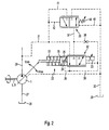
- a hydraulic circuit is shown, which is provided for adjusting an axial piston machine 1.
- the hydrostatic axial piston machine 1 which is driven in the case of a hydraulic pump via the drive shaft 5, sucks pressure medium via a suction line 27 from a tank volume 28 at.
- an arrangement in an open circuit is shown.
- the axial piston machine can also be arranged in a closed circuit.
- the pressure medium sucked in by the hydrostatic axial piston machine 1 is conveyed into a working line 29 in accordance with the set delivery volume.
- the adjusting device 22 is provided for adjusting the delivery volume of the hydraulic pump.
- the adjusting device 22 comprises, in addition to the adjusting piston 26, a setting pressure control valve 32.
- the adjusting pressure control valve 32 sets a control pressure acting on the adjusting piston 26.
- the acting on the actuator piston 26 actuating pressure is taken from the working line 29 via a sampling line 31.
- the actuating piston 26 is acted upon in one direction by a return spring 33 with a spring force.
- a return spring 34 is arranged, which transmits a dependent on the position of the adjusting piston 26 force on a valve piston of the control signal pressure control valve 32.
- the signal pressure control valve 32 is in the rest position of the actuator 22 in his in the Fig. 2 position shown. In this position, the extraction line 31 is connected to a control pressure line 36.
- the control pressure chamber 35 the prevailing in the working line 29 pressure.
- the control pressure control valve 32 can be acted upon in the direction of a second end position with a force.
- This force is generated, for example, by a proportional magnet 23.
- the force of the proportional magnet 23 acts counter to the force of the return spring 34.
- the proportional solenoid 33 is acted upon by a control signal, the valve piston of the control pressure control valve 33 experiences a force in the direction of its second end position.
- the control pressure line 36 is connected to a connecting line 37.
- the signal pressure control valve 32 is continuously adjustable between these two end positions.
- the connection line 37 via a safety valve 39 with the tank line 30 connected.
- control pressure chamber 35 is connected via the connecting line 37 to the tank line 30 and the control pressure chamber 35 is expanded into the tank volume 28.
- the force of the return spring 34 acts opposite to the force of the proportional solenoid 23 on the valve piston of the control pressure control valve 32.
- the force of the return spring 34 acts opposite to the force of the proportional solenoid 23 on the valve piston of the control pressure control valve 32.
- the control pressure line 36 is further connected via a bypass line 36 'to the connecting line 37.
- a throttle point 38 is arranged in the bypass line 36 '. Via the throttle point 38 so that a discharge of pressure medium from the control pressure chamber 35 is made possible, for example, starting from its first end position by acting on the proportional solenoid 23 with a lower control signal, the control pressure control valve 32 is slightly adjusted in the direction of its second end position.
- the safety valve 39 connects in its rest position, the connecting line 27 in the manner already described with the tank line 30.
- This rest position is defined by a safety valve spring 40.
- a further connecting line 41 is connected to the connecting line 37.
- the further connection line 41 branches off from the extraction line 31.
- the pressure prevailing in the further connecting line 41 is further supplied via a first measuring line 42 to a measuring surface formed on the safety valve 39.
- the force acting on the measuring surface hydraulic force acts opposite to the force of the safety valve spring 40.
- the opening differential pressure of the safety valve 39 can be adjusted. If this opening pressure is exceeded by the pressure difference between the pressure supplied via the first measuring line 42 and the second measuring line 43, the safety valve 39 is adjusted in the direction of its second end position. With increasing displacement in the direction of the second end position, the pressure in the control pressure chamber 35 increases, even if the control pressure control valve 32 is in its second end position. As a result, the actuating piston 26 in the Fig. 2 shifted to the left, which results in a reduction in the volume of funding.
- the Fig. 3 shows an enlarged view of a section of an axial piston 101 according to the invention.
- the axial piston machine 101 is shown enlarged in the region of the adjusting device 122.
- the Fig. 1 matching elements and features are provided with reference numbers increased by 100.
- a spherical head 147 is formed at one end of the working piston 111, which protrudes from the cylinder bores 110 of the cylinder drum 106. This spherical head 147 engages in a spherical recess 148 of the sliding shoe 149. From the opposite side, a recess 146 is introduced into the working piston 111.
- the recess 146 is preferably listed as a bore, and dimensioned so that a pressure spring 145 can be arranged therein.
- a lubricating oil bore 150 connects the recess 146 with the head end of the working piston 111.
- the pressure spring 145 is in the untensioned state longer than the maximum distance between the head end of the bore 146 and the opposite end of the cylinder bore 110. The pressure spring 145 thus exerts a force both on the cylinder drum 106 and the working piston 111 from.
- the cylinder drum 106 is held in abutment with the control plate 118.
- the working piston 111 is held together with the slide shoe 149 in contact with the running surface 116 of the swash plate 115.
- a sliding surface 152 is formed on the sliding shoe 149.
- the sliding surface 152 preferably has at least one lubricating oil groove 151.
- the Schmierölnut is connected via a connecting bore with the area in the spherical recess 148.
- the under pressure in the cylinder bore 110 pressure medium is therefore passed through the lubricating oil bore 150 and the connecting hole in the shoe 149 to the Schmierölnut 150 and there provides a hydrostatic relief of the shoe 149.
- the contact surface between the spherical recess 148 and the spherical head 147 supplied with pressure medium for lubrication.
- the spherical recess 148 comprises the spherical head 147 so far that between the working piston 111 and the shoe 149 also tensile forces can be transmitted.
- the actuator 122 is provided.
- the adjusting device 122 comprises an actuating piston 126.
- the actuating piston 126 is identical to the working piston 111. A renewed description of the individual components with respect to the actuating piston 126 is therefore omitted.
- the actuating piston 126 is connected via an articulated connection 113 'with a Stellkolbengleitschuh 149'.
- a spring is also arranged in the recess 146 of the actuating piston 126.
- This spring is designed as a return spring 145 '.
- the return spring 145 ' is supported on the one hand at the head-side end of the recess 146' in the actuating piston 126.
- the opposite end of the feedback spring 145 ' is supported on a spring bearing 147.
- the spring bearing 147 in turn is applied to a first end of a valve piston 158.
- valve piston 158 which depends both on the position of the valve piston 158 and on the position of the actuating piston 126.
- a restoring force is exerted as position information on the actuator piston 158, as with reference to the hydraulic circuit diagram of Fig. 2 has already been explained. This force depends on the position of the swashplate 115 and thus on the set delivery volume.
- the adjusting device 122 comprises an actuator housing 153.
- the actuator housing 153 is inserted into a recess in the connection plate 104, preferably screwed.
- the connection plate 104 closes the housing 103 of the hydrostatic axial piston machine 101.
- the actuator housing 153 has a stepped recess 154.
- the stepped recess 154 is designed as a bore and penetrates the actuator housing 153 along a longitudinal axis 162 of the actuator housing 153.
- the longitudinal axis 162 of the actuator housing 163 is preferably oriented parallel to the axis of rotation 144 of the cylindrical drum 106. Depending on the exact structural design of the connection plate 104, however, a slight deviation from the parallelism may occur by a few degrees.
- a bushing 155 is inserted in the swashplate 115 facing the end of the actuator housing 153.
- the bushing 155 is formed substantially pot-shaped, wherein in the bottom of the bushing 155, a through hole is provided.
- the passage opening of the bushing 155 is arranged approximately in the region of the first end of the valve piston 158 and dimensioned so that the spring bearing 157 can pass.
- the bushing 145 is held in the swash plate end of the adjuster housing 122 by means of a snap ring 160.
- the actuating piston 126 and the valve piston 158 are axially offset from one another in the actuator housing 153.
- the adjusting piston 126 is in operative connection with the valve piston 158 via the return spring 145 '.
- Ring grooves 159, 160 are formed on the valve piston 158.
- connection 161 is connected via a likewise not shown channel with the control pressure chamber 135.
- the valve piston 158 is acted upon by an axial force by the proportional magnet 123, on the other hand, the second annular groove 159 is brought into a position in which the connection 161 is connected to the connection channel 137 in a flow-through manner.
- the connection channel 137 is formed in the terminal plate 104.
- the axial force which is generated by a proportional magnet 123, is transmitted by means of a plunger 159 to the end remote from the spring bearing 157 of the valve piston 158.
- a rest position spring 161 is arranged in the region of the end of the valve piston 158 facing away from the spring bearing 157.
- the rest position spring 161 is supported on the one hand on the Verstellvoriquessgephase 163 and on the other hand on a collar 165 from.
- the adjusting device 122 By forming the adjusting device 122 using parts which are also used as a working piston 111 and as a sliding shoe 149, a considerable simplification of the hydrostatic axial piston machine 101 is achieved. In particular, the production becomes cheaper, because a separate parts production can be avoided for the actuator piston. Furthermore, the production of the swash plate 115 is easy. As in the known from the prior art axial piston machine only a uniformly flat tread 116 must be generated, which extends over the entire circumference of the swash plate 115. Not only is the plurality of working pistons 111 supported on their running surface 116 via their sliding shoes 149, but also a positioning force of the adjusting piston 126 can be transmitted to the running surface 116 by means of the actuating piston sliding shoe 149 '.
- a return spring 133 is disposed on the side facing away from the tread 116 side of the swash plate 115.
- the return spring 133 acts on the swash plate 115 against the actuating force of the actuating piston 126 with a restoring force.
- the supply of the sliding surface 152 'of the Stellkolbengleitschuhs 159' is also comparable to the already described lubrication of the sliding surface 152 of the shoe 149.
- the sliding surface 152 ' is connected via a connecting bore and a lubricating oil hole in the actuating piston 126 with the control pressure chamber 135.
- a lubricating film is generated both between the spherical head of the control piston 126 and on the sliding surface 152 '.
- An exact swing angle adjustment is achieved by reducing the friction.
- the axial piston machine can also be designed as a hydraulic motor.
Landscapes
- Engineering & Computer Science (AREA)
- Mechanical Engineering (AREA)
- General Engineering & Computer Science (AREA)
- Reciprocating Pumps (AREA)
- Hydraulic Motors (AREA)
Claims (8)
- Machine hydrostatique à pistons axiaux, comprenant un tambour à cylindres (106) qui est logé à rotation dans un boîtier (103) et dans lequel des pistons moteurs (111) sont disposés à translation longitudinale dans des alésages (110), lesdits pistons moteurs (111) étant reliés de manière mobile à des patins (149) et lesdits pistons moteurs (111) s'appuyant par le biais des patins (149) sur une surface de glissement (116) d'un disque incliné (115), ainsi qu'un piston de réglage (126) qui agit de concert avec ledit disque incliné (115) pour régler un angle d'inclinaison de la surface de glissement (116) par rapport à un axe de rotation (144) du tambour à cylindres (106), ledit piston de réglage (126) étant relié à un patin de piston de réglage (149') et appliquant via ledit patin de piston de réglage (149') une force de réglage à ladite surface de glissement (116) du disque incliné (115,) caractérisée par le fait que ledit piston de réglage (126) et lesdits pistons moteurs (111) présentent une géométrie identique.
- Machine hydrostatique à pistons axiaux selon la revendication 1, caractérisée par le fait que ledit piston de réglage (126) et ledit patin de piston de réglage (149') sont reliés entre eux par un joint à rotule.
- Machine hydrostatique à pistons axiaux selon la revendication 1 ou 2, caractérisée par le fait que ledit patin de piston de réglage (149') et lesdits patins (149) des pistons moteurs (111) présentent une géométrie identique.
- Machine hydrostatique à pistons axiaux selon l'une quelconque des revendications 1 à 3, caractérisée par le fait que ledit piston de réglage (126) est disposé dans un boîtier de dispositif de réglage (153) de manière à être déplaçable dans le sens longitudinal suivant un axe longitudinal (162) dudit boîtier de dispositif de réglage (153) et que ledit axe longitudinal (162) du boîtier de dispositif de réglage (153) s'étend, au moins approximativement, parallèlement à l'axe de rotation (144) du tambour à cylindres (106).
- Machine hydrostatique à pistons axiaux selon la revendication 4, caractérisée par le fait que ledit piston de réglage (126) est disposé dans un évidement à gradin (154) du boîtier de dispositif de réglage (153) et que, décalé dans la direction axiale par rapport au piston de réglage (126), un piston de soupape (158) est disposé dans ledit évidement à gradin (154).
- Machine hydrostatique à pistons axiaux selon la revendication 4 ou 5, caractérisée par le fait que, pour faire retourner une information de position du piston de réglage (126), un ressort de rappel (145') est prévu qui prend appui sur ledit piston de réglage (126) d'un côté et sur un piston de soupape (158) de l'autre côté.
- Machine hydrostatique à pistons selon la revendication 6, caractérisée par le fait que ledit ressort de rappel (145') est identique à des ressorts de pression (145) insérés dans lesdits évidements cylindriques (110).
- Machine hydrostatique à pistons selon l'une quelconque des revendications 1 à 7, caractérisée par le fait que ledit boîtier de dispositif de réglage (153) est fixé dans une plaque de raccordement (104) de la machine à pistons axiaux (101).
Applications Claiming Priority (2)
| Application Number | Priority Date | Filing Date | Title |
|---|---|---|---|
| DE102006061145A DE102006061145A1 (de) | 2006-12-22 | 2006-12-22 | Hydrostatische Axialkolbenmaschine |
| PCT/EP2007/011303 WO2008077596A1 (fr) | 2006-12-22 | 2007-12-20 | Machine à piston axial hydrostatique |
Publications (2)
| Publication Number | Publication Date |
|---|---|
| EP2092192A1 EP2092192A1 (fr) | 2009-08-26 |
| EP2092192B1 true EP2092192B1 (fr) | 2011-10-19 |
Family
ID=39259629
Family Applications (1)
| Application Number | Title | Priority Date | Filing Date |
|---|---|---|---|
| EP07857026A Not-in-force EP2092192B1 (fr) | 2006-12-22 | 2007-12-20 | Machine à piston axial hydrostatique |
Country Status (6)
| Country | Link |
|---|---|
| US (1) | US20090288552A1 (fr) |
| EP (1) | EP2092192B1 (fr) |
| CN (1) | CN101595304B (fr) |
| AT (1) | ATE529635T1 (fr) |
| DE (1) | DE102006061145A1 (fr) |
| WO (1) | WO2008077596A1 (fr) |
Families Citing this family (16)
| Publication number | Priority date | Publication date | Assignee | Title |
|---|---|---|---|---|
| DE102009006909B4 (de) | 2009-01-30 | 2019-09-12 | Robert Bosch Gmbh | Axialkolbenmaschine mit reduzierter Stelldruckpulsation |
| DE102011113534A1 (de) | 2011-09-15 | 2013-03-21 | Robert Bosch Gmbh | Hydraulische Kolbenmaschine |
| DE102011113533A1 (de) | 2011-09-15 | 2013-03-21 | Robert Bosch Gmbh | Hydrostatische Axialkolbenmaschine |
| DE102012015503A1 (de) * | 2012-08-04 | 2014-02-06 | Robert Bosch Gmbh | Hydrostatische Axialkolbenmaschine |
| DE102012021320A1 (de) * | 2012-10-31 | 2014-04-30 | Robert Bosch Gmbh | Verstellvorrichtung für eine hydrostatische Kolbenmaschine und hydrostatische Kolbenmaschine mit einer derartigen Verstellvorrichtung |
| DE102012022201A1 (de) * | 2012-11-13 | 2014-05-15 | Robert Bosch Gmbh | Verstellvorrichtung für eine Axialkolbenmaschine und Hydromaschine mit einer derartigen Verstellvorrichtung |
| DE102012022997A1 (de) * | 2012-11-24 | 2014-05-28 | Robert Bosch Gmbh | Verstelleinrichtung für eine Hydromaschine und hydraulische Axialkolbenmaschine |
| DE102013220229A1 (de) * | 2013-10-08 | 2015-04-09 | Robert Bosch Gmbh | Schrägscheibenmaschine |
| CN103573616B (zh) * | 2013-11-08 | 2016-03-02 | 无锡威孚精密机械制造有限责任公司 | 柱塞泵的变量缸结构 |
| DE102014211194A1 (de) * | 2014-06-12 | 2015-12-17 | Robert Bosch Gmbh | Hydrostatische Axialkolbenmaschine in Schrägscheibenbauweise und Lüfter mit einer hydrostatischen Axialkolbenmaschine |
| EP3056729B1 (fr) * | 2015-02-11 | 2019-03-27 | Danfoss A/S | Machine à piston axial |
| JP6921071B2 (ja) * | 2015-11-15 | 2021-08-18 | イートン インテリジェント パワー リミテッドEaton Intelligent Power Limited | 油圧ポンプ制御システム |
| DE102015121882A1 (de) * | 2015-11-19 | 2017-05-24 | Linde Hydraulics Gmbh & Co. Kg | Hydrostatische Axialkolbenmaschine |
| CH714321A1 (de) * | 2017-11-11 | 2019-05-15 | Liebherr Machines Bulle Sa | Verstellvorrichtung für eine Axialkolbenmaschine. |
| US10961998B2 (en) * | 2018-03-08 | 2021-03-30 | Hartmann Controls, Inc. | Electro-hydraulic swashplate control arrangement for an axial piston pump |
| US12448955B2 (en) * | 2021-02-16 | 2025-10-21 | Parker-Hannifin Corporation | Displacement control for hydraulic pump |
Family Cites Families (10)
| Publication number | Priority date | Publication date | Assignee | Title |
|---|---|---|---|---|
| GB1073216A (en) * | 1962-11-21 | 1967-06-21 | F W Baggett & Co Ltd | Improvements relating to swash plate pumps and motors |
| US3753627A (en) * | 1971-04-09 | 1973-08-21 | E Ward | Pump bypass liquid control |
| GB1548095A (en) * | 1976-05-10 | 1979-07-04 | Bryce J M | Apparatus and method for attaching a wire to a supporting post |
| US4379389A (en) * | 1980-09-12 | 1983-04-12 | Caterpillar Tractor Co. | Horsepower consumption control for variable displacement pumps |
| JPS5990781A (ja) * | 1982-11-16 | 1984-05-25 | Hitachi Constr Mach Co Ltd | アキシヤルピストン式液圧回転機 |
| FR2793850B1 (fr) * | 1999-05-20 | 2005-10-21 | Renault | Unite hydrostatique a cylindree variable |
| DE19949169C2 (de) * | 1999-10-12 | 2001-10-11 | Brueninghaus Hydromatik Gmbh | Verstellvorrichtung |
| DE10351473B3 (de) * | 2003-11-04 | 2005-07-21 | Brueninghaus Hydromatik Gmbh | Axialkolbenmaschine |
| DE10360452B3 (de) * | 2003-12-22 | 2005-09-08 | Brueninghaus Hydromatik Gmbh | Axialkolbenmaschine mit fixierbarem Gleitstein an der Schrägscheibe |
| US7076946B2 (en) * | 2004-08-16 | 2006-07-18 | Eaton Corporation | Hydraulic kicker control piston |
-
2006
- 2006-12-22 DE DE102006061145A patent/DE102006061145A1/de not_active Withdrawn
-
2007
- 2007-12-20 WO PCT/EP2007/011303 patent/WO2008077596A1/fr not_active Ceased
- 2007-12-20 US US12/520,749 patent/US20090288552A1/en not_active Abandoned
- 2007-12-20 CN CN2007800478562A patent/CN101595304B/zh not_active Expired - Fee Related
- 2007-12-20 AT AT07857026T patent/ATE529635T1/de active
- 2007-12-20 EP EP07857026A patent/EP2092192B1/fr not_active Not-in-force
Also Published As
| Publication number | Publication date |
|---|---|
| ATE529635T1 (de) | 2011-11-15 |
| DE102006061145A1 (de) | 2008-06-26 |
| WO2008077596A1 (fr) | 2008-07-03 |
| CN101595304A (zh) | 2009-12-02 |
| CN101595304B (zh) | 2012-09-26 |
| EP2092192A1 (fr) | 2009-08-26 |
| US20090288552A1 (en) | 2009-11-26 |
Similar Documents
| Publication | Publication Date | Title |
|---|---|---|
| EP2092192A1 (fr) | Machine à piston axial hydrostatique | |
| DE4138313C2 (de) | Radialkolbenpumpe | |
| EP0320822B1 (fr) | Pompe à pistons axiaux | |
| DE102009006909B4 (de) | Axialkolbenmaschine mit reduzierter Stelldruckpulsation | |
| DE19949169C2 (de) | Verstellvorrichtung | |
| EP2179175A1 (fr) | Machine à piston axial du type à plateau oscillant, présentant un dispositif de réglage | |
| DE69510655T2 (de) | Übersetzungssteuerung für ein hydraulisches getriebe | |
| EP0808421B1 (fr) | Pompe hydrostatique ajustable | |
| EP2004996A1 (fr) | Machine a piston hydrostatique avec disque de commande rotatif | |
| EP2024638A1 (fr) | Machine à piston axial avec appui hydrostatique du serre-flan | |
| EP0702755A1 (fr) | Regulateur a plusieurs etages pour pompes a lubrifiant a debit continuellement variable | |
| DE3142230A1 (de) | Mehrzylinder-kompressor | |
| WO2012034619A1 (fr) | Machine à pistons axiaux | |
| EP1853824B1 (fr) | Dispositif et procede pour une alimentation en lubrifiant | |
| EP1438504B1 (fr) | Moteur a piston alternatif a manchon coulissant | |
| DE2100117C3 (de) | Steuerventil für eine hydraulische Stelleinrichtung zur Verstellung eines schwenkbaren Bauteils | |
| EP1565652B1 (fr) | Bloc de raccordement d'une machine a piston hydrostatique | |
| DE19855899B4 (de) | Axialkolbenmaschine | |
| EP1883743A1 (fr) | Machine hydrostatique a pistons fonctionnant selon le principe des coupelles flottantes | |
| DE102009039829A1 (de) | Hydrostatische Axialkolbenpumpe, insbesondere Schrägscheibenpumpe | |
| EP1671032B1 (fr) | Machine a piston hydrostatique munie de deux circuits hydrauliques | |
| DE3726800A1 (de) | Fluegelzellenmaschine | |
| DE4201257C2 (de) | Regelbare Flügelzellenpumpe mit Druckstück | |
| DE2446860A1 (de) | Hydraulische vorrichtung mit radialen kolben mit mehreren hueben je umdrehung, insbesondere motor oder pumpe | |
| EP3749857B1 (fr) | Pompe à pistons axiaux de type à plateau inclinable |
Legal Events
| Date | Code | Title | Description |
|---|---|---|---|
| PUAI | Public reference made under article 153(3) epc to a published international application that has entered the european phase |
Free format text: ORIGINAL CODE: 0009012 |
|
| 17P | Request for examination filed |
Effective date: 20090512 |
|
| AK | Designated contracting states |
Kind code of ref document: A1 Designated state(s): AT BE BG CH CY CZ DE DK EE ES FI FR GB GR HU IE IS IT LI LT LU LV MC MT NL PL PT RO SE SI SK TR |
|
| DAX | Request for extension of the european patent (deleted) | ||
| 17Q | First examination report despatched |
Effective date: 20101014 |
|
| GRAP | Despatch of communication of intention to grant a patent |
Free format text: ORIGINAL CODE: EPIDOSNIGR1 |
|
| GRAS | Grant fee paid |
Free format text: ORIGINAL CODE: EPIDOSNIGR3 |
|
| GRAA | (expected) grant |
Free format text: ORIGINAL CODE: 0009210 |
|
| AK | Designated contracting states |
Kind code of ref document: B1 Designated state(s): AT BE BG CH CY CZ DE DK EE ES FI FR GB GR HU IE IS IT LI LT LU LV MC MT NL PL PT RO SE SI SK TR |
|
| REG | Reference to a national code |
Ref country code: GB Ref legal event code: FG4D Free format text: NOT ENGLISH |
|
| REG | Reference to a national code |
Ref country code: CH Ref legal event code: EP |
|
| REG | Reference to a national code |
Ref country code: IE Ref legal event code: FG4D |
|
| REG | Reference to a national code |
Ref country code: DE Ref legal event code: R096 Ref document number: 502007008483 Country of ref document: DE Effective date: 20111222 |
|
| REG | Reference to a national code |
Ref country code: NL Ref legal event code: VDEP Effective date: 20111019 |
|
| LTIE | Lt: invalidation of european patent or patent extension |
Effective date: 20111019 |
|
| PG25 | Lapsed in a contracting state [announced via postgrant information from national office to epo] |
Ref country code: IS Free format text: LAPSE BECAUSE OF FAILURE TO SUBMIT A TRANSLATION OF THE DESCRIPTION OR TO PAY THE FEE WITHIN THE PRESCRIBED TIME-LIMIT Effective date: 20120219 Ref country code: LT Free format text: LAPSE BECAUSE OF FAILURE TO SUBMIT A TRANSLATION OF THE DESCRIPTION OR TO PAY THE FEE WITHIN THE PRESCRIBED TIME-LIMIT Effective date: 20111019 |
|
| REG | Reference to a national code |
Ref country code: IE Ref legal event code: FD4D |
|
| PG25 | Lapsed in a contracting state [announced via postgrant information from national office to epo] |
Ref country code: LV Free format text: LAPSE BECAUSE OF FAILURE TO SUBMIT A TRANSLATION OF THE DESCRIPTION OR TO PAY THE FEE WITHIN THE PRESCRIBED TIME-LIMIT Effective date: 20111019 Ref country code: NL Free format text: LAPSE BECAUSE OF FAILURE TO SUBMIT A TRANSLATION OF THE DESCRIPTION OR TO PAY THE FEE WITHIN THE PRESCRIBED TIME-LIMIT Effective date: 20111019 Ref country code: SI Free format text: LAPSE BECAUSE OF FAILURE TO SUBMIT A TRANSLATION OF THE DESCRIPTION OR TO PAY THE FEE WITHIN THE PRESCRIBED TIME-LIMIT Effective date: 20111019 Ref country code: PT Free format text: LAPSE BECAUSE OF FAILURE TO SUBMIT A TRANSLATION OF THE DESCRIPTION OR TO PAY THE FEE WITHIN THE PRESCRIBED TIME-LIMIT Effective date: 20120220 Ref country code: SE Free format text: LAPSE BECAUSE OF FAILURE TO SUBMIT A TRANSLATION OF THE DESCRIPTION OR TO PAY THE FEE WITHIN THE PRESCRIBED TIME-LIMIT Effective date: 20111019 Ref country code: GR Free format text: LAPSE BECAUSE OF FAILURE TO SUBMIT A TRANSLATION OF THE DESCRIPTION OR TO PAY THE FEE WITHIN THE PRESCRIBED TIME-LIMIT Effective date: 20120120 |
|
| PG25 | Lapsed in a contracting state [announced via postgrant information from national office to epo] |
Ref country code: CY Free format text: LAPSE BECAUSE OF FAILURE TO SUBMIT A TRANSLATION OF THE DESCRIPTION OR TO PAY THE FEE WITHIN THE PRESCRIBED TIME-LIMIT Effective date: 20111019 |
|
| BERE | Be: lapsed |
Owner name: ROBERT BOSCH G.M.B.H. Effective date: 20111231 |
|
| PG25 | Lapsed in a contracting state [announced via postgrant information from national office to epo] |
Ref country code: SK Free format text: LAPSE BECAUSE OF FAILURE TO SUBMIT A TRANSLATION OF THE DESCRIPTION OR TO PAY THE FEE WITHIN THE PRESCRIBED TIME-LIMIT Effective date: 20111019 Ref country code: MC Free format text: LAPSE BECAUSE OF NON-PAYMENT OF DUE FEES Effective date: 20111231 Ref country code: BG Free format text: LAPSE BECAUSE OF FAILURE TO SUBMIT A TRANSLATION OF THE DESCRIPTION OR TO PAY THE FEE WITHIN THE PRESCRIBED TIME-LIMIT Effective date: 20120119 Ref country code: IE Free format text: LAPSE BECAUSE OF FAILURE TO SUBMIT A TRANSLATION OF THE DESCRIPTION OR TO PAY THE FEE WITHIN THE PRESCRIBED TIME-LIMIT Effective date: 20111019 Ref country code: CZ Free format text: LAPSE BECAUSE OF FAILURE TO SUBMIT A TRANSLATION OF THE DESCRIPTION OR TO PAY THE FEE WITHIN THE PRESCRIBED TIME-LIMIT Effective date: 20111019 Ref country code: DK Free format text: LAPSE BECAUSE OF FAILURE TO SUBMIT A TRANSLATION OF THE DESCRIPTION OR TO PAY THE FEE WITHIN THE PRESCRIBED TIME-LIMIT Effective date: 20111019 Ref country code: EE Free format text: LAPSE BECAUSE OF FAILURE TO SUBMIT A TRANSLATION OF THE DESCRIPTION OR TO PAY THE FEE WITHIN THE PRESCRIBED TIME-LIMIT Effective date: 20111019 |
|
| REG | Reference to a national code |
Ref country code: CH Ref legal event code: PL |
|
| PLBE | No opposition filed within time limit |
Free format text: ORIGINAL CODE: 0009261 |
|
| STAA | Information on the status of an ep patent application or granted ep patent |
Free format text: STATUS: NO OPPOSITION FILED WITHIN TIME LIMIT |
|
| PG25 | Lapsed in a contracting state [announced via postgrant information from national office to epo] |
Ref country code: PL Free format text: LAPSE BECAUSE OF FAILURE TO SUBMIT A TRANSLATION OF THE DESCRIPTION OR TO PAY THE FEE WITHIN THE PRESCRIBED TIME-LIMIT Effective date: 20111019 Ref country code: RO Free format text: LAPSE BECAUSE OF FAILURE TO SUBMIT A TRANSLATION OF THE DESCRIPTION OR TO PAY THE FEE WITHIN THE PRESCRIBED TIME-LIMIT Effective date: 20111019 |
|
| 26N | No opposition filed |
Effective date: 20120720 |
|
| GBPC | Gb: european patent ceased through non-payment of renewal fee |
Effective date: 20120119 |
|
| PG25 | Lapsed in a contracting state [announced via postgrant information from national office to epo] |
Ref country code: BE Free format text: LAPSE BECAUSE OF NON-PAYMENT OF DUE FEES Effective date: 20111231 Ref country code: GB Free format text: LAPSE BECAUSE OF NON-PAYMENT OF DUE FEES Effective date: 20120119 Ref country code: CH Free format text: LAPSE BECAUSE OF NON-PAYMENT OF DUE FEES Effective date: 20111231 Ref country code: LI Free format text: LAPSE BECAUSE OF NON-PAYMENT OF DUE FEES Effective date: 20111231 |
|
| REG | Reference to a national code |
Ref country code: DE Ref legal event code: R097 Ref document number: 502007008483 Country of ref document: DE Effective date: 20120720 |
|
| PG25 | Lapsed in a contracting state [announced via postgrant information from national office to epo] |
Ref country code: MT Free format text: LAPSE BECAUSE OF FAILURE TO SUBMIT A TRANSLATION OF THE DESCRIPTION OR TO PAY THE FEE WITHIN THE PRESCRIBED TIME-LIMIT Effective date: 20111019 |
|
| PGFP | Annual fee paid to national office [announced via postgrant information from national office to epo] |
Ref country code: IT Payment date: 20121221 Year of fee payment: 6 |
|
| PG25 | Lapsed in a contracting state [announced via postgrant information from national office to epo] |
Ref country code: ES Free format text: LAPSE BECAUSE OF FAILURE TO SUBMIT A TRANSLATION OF THE DESCRIPTION OR TO PAY THE FEE WITHIN THE PRESCRIBED TIME-LIMIT Effective date: 20120130 |
|
| PGFP | Annual fee paid to national office [announced via postgrant information from national office to epo] |
Ref country code: DE Payment date: 20130225 Year of fee payment: 6 Ref country code: FR Payment date: 20130123 Year of fee payment: 6 |
|
| PG25 | Lapsed in a contracting state [announced via postgrant information from national office to epo] |
Ref country code: LU Free format text: LAPSE BECAUSE OF NON-PAYMENT OF DUE FEES Effective date: 20111220 |
|
| PG25 | Lapsed in a contracting state [announced via postgrant information from national office to epo] |
Ref country code: FI Free format text: LAPSE BECAUSE OF FAILURE TO SUBMIT A TRANSLATION OF THE DESCRIPTION OR TO PAY THE FEE WITHIN THE PRESCRIBED TIME-LIMIT Effective date: 20111019 |
|
| PG25 | Lapsed in a contracting state [announced via postgrant information from national office to epo] |
Ref country code: TR Free format text: LAPSE BECAUSE OF FAILURE TO SUBMIT A TRANSLATION OF THE DESCRIPTION OR TO PAY THE FEE WITHIN THE PRESCRIBED TIME-LIMIT Effective date: 20111019 |
|
| PG25 | Lapsed in a contracting state [announced via postgrant information from national office to epo] |
Ref country code: HU Free format text: LAPSE BECAUSE OF FAILURE TO SUBMIT A TRANSLATION OF THE DESCRIPTION OR TO PAY THE FEE WITHIN THE PRESCRIBED TIME-LIMIT Effective date: 20111019 |
|
| REG | Reference to a national code |
Ref country code: AT Ref legal event code: MM01 Ref document number: 529635 Country of ref document: AT Kind code of ref document: T Effective date: 20121220 |
|
| PG25 | Lapsed in a contracting state [announced via postgrant information from national office to epo] |
Ref country code: AT Free format text: LAPSE BECAUSE OF NON-PAYMENT OF DUE FEES Effective date: 20121220 |
|
| REG | Reference to a national code |
Ref country code: DE Ref legal event code: R119 Ref document number: 502007008483 Country of ref document: DE |
|
| REG | Reference to a national code |
Ref country code: DE Ref legal event code: R119 Ref document number: 502007008483 Country of ref document: DE Effective date: 20140701 |
|
| REG | Reference to a national code |
Ref country code: FR Ref legal event code: ST Effective date: 20140829 |
|
| PG25 | Lapsed in a contracting state [announced via postgrant information from national office to epo] |
Ref country code: DE Free format text: LAPSE BECAUSE OF NON-PAYMENT OF DUE FEES Effective date: 20140701 |
|
| PG25 | Lapsed in a contracting state [announced via postgrant information from national office to epo] |
Ref country code: FR Free format text: LAPSE BECAUSE OF NON-PAYMENT OF DUE FEES Effective date: 20131231 |
|
| PG25 | Lapsed in a contracting state [announced via postgrant information from national office to epo] |
Ref country code: IT Free format text: LAPSE BECAUSE OF NON-PAYMENT OF DUE FEES Effective date: 20131231 |
|
| PG25 | Lapsed in a contracting state [announced via postgrant information from national office to epo] |
Ref country code: IT Free format text: LAPSE BECAUSE OF NON-PAYMENT OF DUE FEES Effective date: 20131220 |