EP2092286B1 - Integrierte gesamtlufttemperatursonde und elektronik - Google Patents
Integrierte gesamtlufttemperatursonde und elektronik Download PDFInfo
- Publication number
- EP2092286B1 EP2092286B1 EP07869574A EP07869574A EP2092286B1 EP 2092286 B1 EP2092286 B1 EP 2092286B1 EP 07869574 A EP07869574 A EP 07869574A EP 07869574 A EP07869574 A EP 07869574A EP 2092286 B1 EP2092286 B1 EP 2092286B1
- Authority
- EP
- European Patent Office
- Prior art keywords
- sensing element
- electronics
- temperature
- temperature sensing
- total air
- Prior art date
- Legal status (The legal status is an assumption and is not a legal conclusion. Google has not performed a legal analysis and makes no representation as to the accuracy of the status listed.)
- Active
Links
Images



Classifications
-
- G—PHYSICS
- G01—MEASURING; TESTING
- G01K—MEASURING TEMPERATURE; MEASURING QUANTITY OF HEAT; THERMALLY-SENSITIVE ELEMENTS NOT OTHERWISE PROVIDED FOR
- G01K13/00—Thermometers specially adapted for specific purposes
- G01K13/02—Thermometers specially adapted for specific purposes for measuring temperature of moving fluids or granular materials capable of flow
-
- G—PHYSICS
- G01—MEASURING; TESTING
- G01K—MEASURING TEMPERATURE; MEASURING QUANTITY OF HEAT; THERMALLY-SENSITIVE ELEMENTS NOT OTHERWISE PROVIDED FOR
- G01K13/00—Thermometers specially adapted for specific purposes
- G01K13/02—Thermometers specially adapted for specific purposes for measuring temperature of moving fluids or granular materials capable of flow
- G01K13/028—Thermometers specially adapted for specific purposes for measuring temperature of moving fluids or granular materials capable of flow for use in total air temperature [TAT] probes
Definitions
- the present invention relates to a sensor for determining total air temperature. It finds particular application in conjunction with a total air temperature sensor including both an integrated probe and integrated electronics and will be described with particular reference thereto. It will be appreciated, however, that the invention is also amenable to other applications.
- a total air temperature (TAT) sensor is used on an air vehicle (e.g., aircraft) to determine, for example, total temperature, true airspeed, Mach number, etc. of the air vehicle moving through an air mass.
- Current distributed air data architectures rely on TAT sensors with analog (resistance) outputs that are wired to an air data computer at a remote location onboard the air vehicle.
- the air data computer monitors and controls a heater on the TAT sensor for reducing the risk of ice formation.
- the remote location of the air data computer requires circuitry, including cables, for transmitting the analog resistance outputs from the TAT sensor to the air data computer.
- Heated TAT sensors also require the air data computer or other devices to provide heater control and monitoring.
- Such circuits increase the size and complexity of the device containing these circuits (e.g., the air data computer).
- Transmitting signals along cables on the aircraft creates certain drawbacks. For example, signal loss tends to occur over the inter-connection cables.
- the inter-connection cables are susceptible to electrical noise, which may interfere with the transmitted signal.
- the interface requirements between the inter-connection cables and the air data computer are relatively complex.
- the present invention provides a new and improved apparatus and method which addresses the above-referenced problems.
- US2003/058919 discloses a total air temperature (TAT) probe including an inlet scoop receiving airflow from free stream airflow moving toward the inlet scoop from a first direction. A portion of the air enters a TAT sensor flow passage. An angle through which the internal air turns is increased to enhance inertial extraction of ice and water particles.
- EP-A-1275947 discloses generating a total air temperature (TAT) that is compensated for recovery of de-icing heater error based on a local angle of attack for the TAT probe.
- EP-A-1491900 discloses a multi-function air data sensing probe having an angle of attack vane.
- a strut is mounted on an aircraft and includes a passageway for a total air temperature sensor having an inlet scoop offset from a chamber so that air changes direction when it enters the chamber.
- EP-A-1602905 discloses a temperature sensor having at least two thermometers or temperature sensing elements. A processor determines a total temperature based on temperatures from each of the thermometers.
- a vehicle with a total air temperature sensor comprising: a probe, the probe including: an air inlet; a temperature sensing element being located so that air flowing into the air inlet passes by the temperature sensing element, the temperature sensing element being adapted to produce a temperature sensing element electrical signal as a function of a temperature of the air passing by the temperature sensing element; a housing; and a heater for deicing the housing; and an electronics package integrated with the probe, electronics in the electronics package being adapted to receive the temperature sensing element electrical signal from the temperature sensing element and to determine a total air temperature as a function of the temperature sensing element electrical signal: characterized in that the electronics package includes: an interface temperature sensor adapted to monitor a temperature at an interface between the integrated probe and electronics package and a skin of the vehicle, the heater being adapted to be turned-off if the temperature at the interface is above a predetermined threshold.
- FIGURE 3 illustrates single-channel TATs communicating with respective air data computers according to one embodiment of an apparatus illustrating principles of the present invention
- FIGURE 4 illustrates a dual-channel TAT communicating with air data computers according to one embodiment of an apparatus illustrating principles of the present invention
- FIGURE 5 illustrates a single-channel Integrated TAT integrated with an air data system according to the embodiment illustrated in FIGURE 2 ;
- FIGURE 6 illustrates a redundant dual-channel Integrated TAT integrated with an air data system according to the embodiment illustrated in FIGURE 2 .
- the TAT sensor 10 includes a probe 12 and an electronics package 14. In one embodiment, the probe 12 is integrated with the electronics package 14.
- the probe 12 includes an air inlet 16, a main exit channel 18, a sensor flow passage 20, and a sensor assembly 22, which includes a thermometer or temperature sensing element 24 for sensing the temperature of the air in the sensor flow passage 20.
- a heater 26 is embedded in a housing 30 of the probe 12. In one embodiment, the heater 26 is used as a deicing heater. The temperature sensed by the sensing element 24 may be affected by the heater 26. Therefore, a radiation shield 32 (e.g., heat shield) is provided around the sensing element 24 to reduce sensing errors.
- a portion of the air entering the air inlet 16 exits the main exit channel 18 while another portion of the air enters the sensor flow passage 20. The temperature of the portion of air entering the sensor flow passage 20 is measured by the sensing element 24 before the air in the sensor flow passage 20 exits via respective ports 34, 36 in the sensor flow passage 20 and the housing 30.
- An aircraft skin 38 (surface) supports the probe 12. More specifically, the sensor 10 is installed in a hole in the skin 38, attached directly to skin 38 itself or to a doubler plate (e.g., a structural reinforcement on the inside of the skin).
- the skin 38 is a carbon composite material; however, other materials are contemplated for the aircraft skin 38 in other embodiments.
- a duct 40 provides a path for electrical connections 42, 44 (e.g., electrical wires) between the probe 12 and the electronics package 14, respectively.
- electrical connections 42, 44 e.g., electrical wires
- the acceptable temperature for carbon composite skins 38 (e.g., between about 60°C and 90°C) is lower than a traditional metal skin could endure.
- the environmental and electromagnetic requirements are relatively more stringent than electronics bays and other locations where electronics are normally installed. For example, if the skin is no longer metal, a probe 12 that may be metal becomes an antenna for lightning strikes and, therefore, increased lightning protection is desired. It is contemplated that the integrated electronics 14 house such lightning protection 47.
- the electronics package 14 includes an analog/digital converter 46, a power regulator 48, a central processing unit (CPU) 50, an I/O bus 52, a heater monitor/ control device 54, and an end plate temperature sensor 49, which monitors a temperature of a base plate 51 of the sensor 10.
- the base plate 51 contacts the aircraft skin 38.
- the power regulator 48 regulates power to 15 VDC, 28 VDC, or 115 VAC.
- the I/O bus 52 is a communication bus such as a CAN Bus, ARINC429, or Flexray (over plastic fiber optic).
- the heater monitor/control device 54 either simply monitors operation of the heater 26 or both monitors and controls operation of the heater 26.
- the heater monitor/ control device 54 monitors the heater 26 by sensing an electrical current supplied to the heater 26 and controls current to the heater 26 via a switch operable by an operator of the vehicle to turn the heater 26 on/off, if the device 54 is acting only as a monitor device.
- the heater monitor/control device 54 controls the heater 26 by automatically turning the heater 26 on/off using aircraft configuration inputs (e.g., Weight on Wheels (WOW), airspeed, etc.), if the device 54 is also acting as a control device.
- aircraft configuration inputs e.g., Weight on Wheels (WOW), airspeed, etc.
- the analog/digital converter 46 electrically communicates with the temperature sensing element 24, which produces an analog signal as a function of (e.g., representative of) the air temperature in the sensor flow passage 20.
- the analog/digital converter 46 produces a digital signal as a function of the analog signal received from the sensing element 24.
- the digital signal is transmitted from the analog/digital converter 46 to the CPU 50 via the I/O bus 52.
- the CPU 50 also electrically communicates with the heater monitor/control device 54 for determining whether the heater 26 is on/off.
- the CPU 50 calculates the TAT as a function of at least the temperature sensed by the sensing element 24 and/or a status of the heater 26 (e.g., whether the heater 26 is on/off).
- the CPU 50 determines that the TAT is the temperature sensed by the sensing element 24. On the other hand, if the heater 26 is on, the CPU 50 determines the TAT by, for example, multiplying the temperature sensed by the sensing element 24 by a constant.
- the TAT is transmitted from the CPU 50 to other systems (not shown) on the aircraft via the bus I/O 52.
- the TAT is transmitted from the CPU 50 to flight management computers, engine computers, air data computers, and/or other computing devices on the aircraft for determining true air speed, fuel efficiency, and/or engine settings, etc.
- the end plate sensor 49 electrically communicates with the CPU 50 and/or the heater monitor/control device 54 and causes the heater 26 and/or the sensing element 24 to turn-off once the heater 26 and/or the sensing element 24 rise above a predetermined threshold. Turning-off the sensing element 24 and/or the heater 26 above the predetermined threshold helps reduce the possibility that the skin 38 (e.g., carbon composite skin) will be damaged from overheating at the interface 45 between the base plate and the skin 38 when, for example, the aircraft is on the ground in a relatively warm environment. Typically, the sensing element 24 and/or the heater 26 will not need to be turned-off while the aircraft is in flight since the air passing over the skin 38 tends to cool the sensing element 24 and the heater 26.
- the skin 38 e.g., carbon composite skin
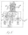
- FIGURE 2 A second embodiment of the present invention is illustrated in FIGURE 2 .
- like components from FIGURE 1 are designated by like numerals with a primed (') suffix and new components are designated by new numerals.
- the probe 12' includes a second sensor assembly 60, which includes a second thermometer or temperature sensing element 62 for sensing the temperature of air in the sensor flow passage.
- the electronics package 14' includes the analog/digital converter 46', power regulator 48', CPU 50', I/O bus 52', and heater monitor/control device 54', which are electrically connected to the sensor assembly 22' as described above with reference to FIGURE 1 .
- the electronics package 14' also includes a second analog/digital converter 64, a second power regulator 66, a second CPU 68, and a second I/O bus 70, which are electrically connected to the second sensor assembly 60.
- the heater monitor/control device 54' is also electrically connected to the second sensor assembly 60.
- the analog/digital converter 46' electrically communicates with the temperature sensing element 24', which produces an analog signal as a function of the air temperature in the sensor flow passage.
- the analog/digital converter 46' produces a digital signal as a function of the analog signal received from the sensing element 24'.
- the digital signal is transmitted from the analog/digital converter 46' to the CPU 50' via the I/O bus 52'.
- the CPU 50' also electrically communicates with the heater monitor/control device 54' for determining whether the heater is on/off.
- the CPU 50' calculates the TAT as a function of the temperature sensed by the sensing element 24' and whether the heater is on/off.
- the CPU 50' determines that the TAT is the temperature sensed by the sensing element 24'. On the other hand, if the heater is on, the CPU 50' determines the TAT by, for example, multiplying the temperature sensed by the sensing element 24' by a constant.
- the analog/digital converter 64 electrically communicates with the second temperature sensing element 62, which produces an analog signal as a function of the air temperature in the sensor flow passage.
- the analog/digital converter 64 produces a digital signal as a function of the analog signal received from the sensing element 62.
- the digital signal is transmitted from the analog/digital converter 64 to the CPU 68 via the I/O bus 70.
- the CPU 68 also electrically communicates with the heater monitor/control device 54' for determining whether the heater is on/off.
- the CPU 68 calculates the TAT as a function of the temperature sensed by the sensing element 62 and whether the heater is on/off.
- the CPU 68 determines that the TAT is the temperature sensed by the sensing element 62. On the other hand, if the heater is on, the CPU 68 determines the TAT by, for example, multiplying the temperature sensed by the sensing element 62 by a constant.
- the analog/digital converter 46', power regulator 48', CPU 50', I/O bus 52', heater monitor/control device 54', and sensor assembly 22' are electrically independent from the second analog/digital converter 64, second power regulator 66, second CPU 68, and second I/O bus 70, and second sensor assembly 60.
- the CPU 50' and second CPU 68 are both electrically connected to the heater monitor/control device 54'.
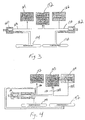
- FIGURE 3 illustrates single-channel TATs 160, 162 communicating with respective air data computers 164, 166 via respective data buses 168, 170. Both of the TATs 160, 162 also communicate with the aircraft Flight Management System (FMS), Engine Controller, and other TAT consumers, collectively represented as 172, via the respective data buses 168, 170. The TATs 160, 162 also receive heater power and electronic power via respective aircraft power buses 174, 176.
- FMS Flight Management System
- Engine Controller Engine Controller
- FIGURE 4 illustrates a dual-channel TAT 180 communicating with air data computers 182, 184 via respective data buses 186, 188.
- the TAT 180 also communicates with the aircraft Flight Management System (FMS), Engine Controller, and other TAT consumers, collectively represented as 190, via the respective data buses 186, 188.
- the TAT 180 also receives first heater power and first electronic power via a first aircraft power bus 192.
- the TAT 180 also receives second heater power and second electronic power via a second aircraft power bus 194.
- FIGURE 5 illustrates a single-channel TAT integrated into an air data system according to the embodiment illustrated in FIGURE 2 .
- two (2) TAT sensors 80, 82 are positioned on opposite sides of an aircraft. Each of the TAT sensors 80, 82 operates as described above.
- the first TAT sensor 80 is electrically connected to an air data section 84 of a first computer 86, which is onboard the aircraft, and an opposite side pressure (OSP) section 88 of a second computer 90, which is also onboard the aircraft.
- the second TAT sensor 82 is electrically connected to an air data section 92 of the second computer 90 and an OSP section 94 of the first computer 86.
- OSP opposite side pressure
- Data is transmitted between i) the first TAT sensor 80 and ii) the air data section 84 of the first computer 86 and the OSP section 88 of the second computer 90 via a data line 100; and power is transmitted to the first TAT sensor 80 and the OSP section 88 of the second computer 90 from the air data section 84 of the first computer 86 via a power line 102.
- data is transmitted between i) the second TAT sensor 82 and ii) the air data section 92 of the second computer 90 and the OSP section 94 of the first computer 86 via a data line 104; and power is transmitted to the second TAT sensor 82 and the OSP section 94 of the first computer 86 from the air data section 92 of the second computer 90 via a power line 106.
- FIGURE 6 illustrates a dual channel redundant air data system according to the embodiment illustrated in FIGURE 2 .
- two (2) TAT sensors 110, 112 are positioned on opposite sides of an aircraft. Each of the TAT sensors 110, 112 operates as described above.
- the first TAT sensor 110 is electrically connected to an air data section 114 of a Pilot computer 116, which is onboard the aircraft, and an OSP section 118 of a first standby computer 120, which is also onboard the aircraft.
- the first TAT sensor 110 is also electrically connected to an air data section 122 of a second standby computer 124, which is also onboard the aircraft, and an OSP section 126 of a Co-Pilot computer 128, which is also onboard the aircraft.
- Data is transmitted between i) the first TAT sensor 110 and ii) the air data section 114 of the Pilot computer 116 and the OSP section 118 of the first standby computer 120 via a data line 130; and power is transmitted to the first TAT sensor 110 and the OSP section 118 of the first standby computer 120 from the air data section 114 of the Pilot computer 116 via a power line 132.
- Data is transmitted between i) the first TAT sensor 110 and ii) the OSP section 126 of the Co-Pilot computer 128 and the air data section 122 of the second standby computer 124 via a data line 134; and power is transmitted to the first TAT sensor 110 and the OSP section 126 of the Co-Pilot computer 128 from the air data section 122 of the second standby computer 124 via a power line 126.
- the second TAT sensor 112 is electrically connected to an OSP section 140 of the Pilot computer 116 and an air data section 142 of the first standby computer 120.
- the second TAT sensor 112 is also electrically connected to an OSP section 144 of the second standby computer 124 and an air data section 146 of the Co-Pilot computer 128.
- Data is transmitted between i) the second TAT sensor 112 and ii) the OSP section 140 of the Pilot computer 116 and the air data section 142 of the first standby computer 120 via a data line 148; and power is transmitted to the second TAT sensor 112 and the OSP section 140 of the Pilot computer 116 from the air data section 142 of the first standby computer 120 via a power line 150.
- Data is transmitted between i) the second TAT sensor 112 and ii) the air data section 146 of the Co-Pilot computer 128 and the OSP section 144 of the second standby computer 124 via a data line 152; and power is transmitted to the second TAT sensor 112 and the OSP section 144 of the second standby computer 124 from the air data section 146 of the Co-Pilot computer 128 via a power line 154.
Landscapes
- Physics & Mathematics (AREA)
- General Physics & Mathematics (AREA)
- Arrangements For Transmission Of Measured Signals (AREA)
- Measuring Temperature Or Quantity Of Heat (AREA)
Claims (11)
- Fahrzeug mit einem Gesamtlufttemperatursensor, wobei der Gesamtlufttemperatursensor (10) aufweist:eine Sonde (12), wobei die Sonde aufweist:einen Lufteinlass (16);ein Temperaturerfassungselement (24), das derart angeordnet ist, dass in den Lufteinlass (16) strömende Luft an dem Temperaturerfassungselement (24) entlang strömt, wobei das Temperaturerfassungselement (24) geeignet ist, ein elektrisches Temperaturerfassungselement-Signal als Funktion der Temperatur der an dem Temperaturerfassungselement (24) entlang strömenden Luft zu erzeugen;ein Gehäuse (30); undeine Heizeinrichtung (26) zum Enteisen des Gehäuses (30); undeine in der Sonde (12) integrierte Elektronikeinheit (14), wobei die Elektronik in der Elektronikeinheit (14) in der Lage ist, das elektrische Temperaturerfassungselement-Signal von dem Temperaturerfassungselement zu empfangen und eine Gesamtlufttemperatur als Funktion des elektrischen Temperaturerfassungselement-Signals zu bestimmen;dadurch gekennzeichnet, dass die Elektronikeinheit (14) aufweist:einen Grenzfilächentemperatursensor (49), der in der Lage ist, die Temperatur an einer Grenzfläche zwischen der integrierten Einheit aus Sonde (12) und Elektronikeinheit (14) und einer Außenhaut (38) des Fahrzeugs zu überwachen, wobei die Heizeinrichtung (30) abschaltbar ist, wenn die Temperatur an der Grenzfläche über einem vorbestimmten Schwellenwert liegt.
- Fahrzeug mit dem Gesamtlufttemperatursensor (10) nach Anspruch 1, ferner mit:einem elektrischen Leiter (42, 44), der in elektrischer Verbindung mit der Sonde und der Elektronik in der Elektronikeinheit (14) steht, wobei das elektrische Temperaturerfassungselement-Signal von dem Temperaturerfiassungselement (24) über den elektrischen Leiter (42, 44) an die Elektronik übermittelt wird.
- Fahrzeug mit dem Gesamtlufittemperatursensor (10) nach Anspruch 1, bei welchem:die Elektronik in der Lage ist, ein elektrisches Elektronik-Signal als Funktion der Gesamtlufttemperatur zu erzeugen; unddie Elektronik in der Lage ist, ein elektrisches Signal an zusätzliche elektrische Systeme in dem Fahrzeug zu übertragen, um zumindest die tatsächliche Lufitgeschwindigkeit und/oder die Krafitstofifeffizienz und/oder Motoreinstellungen zu bestimmen.
- Fahrzeug mit dem Gesamtlufttemperatursensor (10) nach Anspruch 1, bei welchem die Elektronik in der Lage ist, die Gesamtfufittemperatur als Funktion des Zustands der Heizeinrichtung (30) zu bestimmen.
- Fahrzeug mit dem Gesamtlufttemperatursensor (10) nach Anspruch 1, bei welchem :die Sonde ferner aufweist:ein zweites Temperaturerfassungselement (62), das in der Lage ist, ein zweites elektrisches Temperaturerfassungselement-Signal als Funktion der Lufttemperatur zu erzeugen; unddie Elektronikeinheit ferner aufweist:eine zweite Elektronik, die in der Lage ist, das zweite elektrische Temperaturerfassungselement-Signal von dem zweiten Temperaturerfassungselement (62) zu empfangen und eine zweite Gesamtlufttemperatur als Funktion des zweiten elektrischen Temperaturerfassungselement-Signals zu bestimmen.
- Fahrzeug mit dem Gesamtlufttemperatursensor (10) nach Anspruch 5, bei welchem:ein elektrisches Bauteil in der Elektronik elektrisch unabhängig von einem entsprechenden elektrischen Bauteil in der zweiten Elektronik ist.
- Fahrzeug mit dem Gesamtlufttemperatursensor (10) nach Anspruch 5, bei welchem:die Sonde (12) ferner aufweist:einen Monitor (54) zum Überwachen des Zustands der Heizeinrichtung;wobei der Monitor (54) elektrisch mit einem elektrischen Bauteil in der Elektronik und einem entsprechenden elektrischen Bauteil in der zweiten Elektronik kommuniziert;unddie Elektronik und die zweite Elektronik ebenfalls die Gesamtlufttemperatur als Funktion des Zustands der Heizeinrichtung (30) bestimmen.
- Fahrzeug mit dem Gesamtlufttemperatursensor (10) nach Anspruch 1, ferner mit einer zweiten Sonde (12') mit:einem zweiten Lufteinlass; undeinem zweiten Temperaturerfassungselement (62), das derart angeordnet ist, dass in den zweiten Lufteinlass strömende Luft an dem zweiten Temperaturerfassungselement (62) entlang strömt, wobei das zweite Temperaturerfassungselement (62) geeignet ist, ein elektrisches Temperaturerfassungselement-Signal als Funktion der Temperatur der an dem zweiten Temperaturerfassungselement (62) entlang strömenden Luft zu erzeugen; undferner mit einer in der zweiten Sonde (12') integrierten zweiten Elektronikeinheit (14'), wobei die zweite Elektronik in der zweiten Elektronikeinheit (14') in der Lage ist, das elektrische Signal des zweiten Temperaturerfassungselements von dem zweiten Temperaturerfassungselement (62) zu empfangen und eine zweite Gesamtlufttemperatur als Funktion des elektrischen Signals des zweiten Temperaturerfassungselements (62) zu bestimmen.
- Fahrzeug mit dem Gesamtlufttemperatursensor (10) nach Anspruch 8, bei welchem :die Sonde (12) mechanisch und elektrisch von der zweiten Sonde (12') unabhängig ist;die Elektronik mechanisch und elektrisch von der zweiten Elektronik unabhängig ist;die Elektronik elektrisch mit einer ersten elektronischen Rechenvorrichtung in dem Fahrzeug kommuniziert;die zweite Elektronik elektrisch mit einer zweiten elektronischen Rechenvorrichtung in dem Fahrzeug kommuniziert; unddie erste elektronische Rechenvorrichtung elektrisch von der zweiten elektronischen Rechenvorrichtung unabhängig ist.
- Fahrzeug mit dem Gesamtlufttemperatursensor (10) nach Anspruch 1, bei welchem die integrierte Einheit aus Sonde und Elektronikeinheit in einer Öffnung der Außenhaut (38) des Fahrzeugs angeordnet ist.
- Fahrzeug mit dem Gesamtlufttemperatursensor (10) nach Anspruch 10, bei welchem die Fahrzeugaußenhaut (38) aus einem Carbon-Verbundmaterial besteht.
Applications Claiming Priority (2)
| Application Number | Priority Date | Filing Date | Title |
|---|---|---|---|
| US87071606P | 2006-12-19 | 2006-12-19 | |
| PCT/US2007/088226 WO2008077131A2 (en) | 2006-12-19 | 2007-12-19 | Integrated total air temperature probe and electronics |
Publications (2)
| Publication Number | Publication Date |
|---|---|
| EP2092286A2 EP2092286A2 (de) | 2009-08-26 |
| EP2092286B1 true EP2092286B1 (de) | 2011-11-16 |
Family
ID=39430039
Family Applications (1)
| Application Number | Title | Priority Date | Filing Date |
|---|---|---|---|
| EP07869574A Active EP2092286B1 (de) | 2006-12-19 | 2007-12-19 | Integrierte gesamtlufttemperatursonde und elektronik |
Country Status (8)
| Country | Link |
|---|---|
| US (1) | US7854548B2 (de) |
| EP (1) | EP2092286B1 (de) |
| JP (1) | JP2010513939A (de) |
| CN (1) | CN101606048B (de) |
| AT (1) | ATE534023T1 (de) |
| BR (1) | BRPI0720526A2 (de) |
| ES (1) | ES2374996T3 (de) |
| WO (1) | WO2008077131A2 (de) |
Families Citing this family (27)
| Publication number | Priority date | Publication date | Assignee | Title |
|---|---|---|---|---|
| US9310256B2 (en) * | 2012-05-22 | 2016-04-12 | Unison Industries, Llc | Process sensor with convective increaser |
| WO2013177695A1 (en) * | 2012-05-31 | 2013-12-05 | UNIVERSITé LAVAL | Method and apparatus for determining an icing condition status of an environment |
| US9658117B2 (en) * | 2012-08-18 | 2017-05-23 | Rosemount Aerospace Inc. | Total air temperature probes for reducing deicing heater error |
| US9429481B2 (en) | 2012-08-31 | 2016-08-30 | Ametek, Inc. | Apparatus and method for measuring total air temperature within an airflow |
| US9829395B2 (en) * | 2012-12-13 | 2017-11-28 | Rosemount Aerospace Inc. | Air temperature sensor arrangement for a vehicle and method of measuring air temperature |
| CN104833444B (zh) * | 2013-10-16 | 2018-11-13 | 罗斯蒙特航天公司 | 总空气温度传感器 |
| US9689755B2 (en) | 2013-10-22 | 2017-06-27 | Rosemount Aerospace Inc. | Temperature sensors |
| CN105987773B (zh) * | 2015-01-27 | 2018-11-30 | 成都凯天电子股份有限公司 | 阻滞式总温传感器 |
| US20160238456A1 (en) * | 2015-02-12 | 2016-08-18 | Rosemount Aerospace Inc. | Air temperature sensor and fabrication |
| US10281303B2 (en) * | 2015-03-23 | 2019-05-07 | Rosemount Aerospace, Inc. | Air data probe with improved performance at angle of attack operation |
| US10337931B2 (en) * | 2017-01-05 | 2019-07-02 | Honeywell International Inc. | Systems and methods for icing resistant total air temperature probes with air jets |
| US10422702B2 (en) * | 2017-06-08 | 2019-09-24 | Rosemount Aerospace Inc. | Total air temperature probe with reduced icing sensor flow passage geometry |
| US10585007B2 (en) | 2017-06-22 | 2020-03-10 | Unison Industries, Llc | Air temperature sensor |
| US10578498B2 (en) | 2017-06-22 | 2020-03-03 | Unison Industries, Llc | Air temperature sensor |
| US10545057B2 (en) | 2017-06-22 | 2020-01-28 | Unison Industries, Llc | Air temperature sensor and method of reducing error |
| USD844466S1 (en) | 2017-06-22 | 2019-04-02 | Unison Industries, Llc | Temperature sensor |
| US10605675B2 (en) | 2017-06-22 | 2020-03-31 | Unison Industries, Llc | Air temperature sensor |
| US10716171B2 (en) | 2018-03-23 | 2020-07-14 | Rosemount Aerospace Inc. | Power efficient heater control of air data sensor |
| US11105691B2 (en) * | 2018-03-30 | 2021-08-31 | Honeywell International Inc. | Self-regulating heating system for a total air temperature probe |
| US10852203B2 (en) * | 2018-06-15 | 2020-12-01 | Rosemount Aerospace Inc. | Total air temperature probe with concave flow path transitions to outlet |
| US11524790B2 (en) | 2018-08-21 | 2022-12-13 | Honeywell International Inc. | Enhanced pitot tube power management system and method |
| CN109708778A (zh) * | 2018-12-07 | 2019-05-03 | 苏州长风航空电子有限公司 | 一种防冰温度传感器及其制备方法 |
| US11639954B2 (en) | 2019-05-29 | 2023-05-02 | Rosemount Aerospace Inc. | Differential leakage current measurement for heater health monitoring |
| US11472562B2 (en) * | 2019-06-14 | 2022-10-18 | Rosemount Aerospace Inc. | Health monitoring of an electrical heater of an air data probe |
| US11627014B2 (en) | 2019-08-06 | 2023-04-11 | Rosemount Aerospace Inc. | Distributed electric air data module system |
| US11930563B2 (en) | 2019-09-16 | 2024-03-12 | Rosemount Aerospace Inc. | Monitoring and extending heater life through power supply polarity switching |
| CN119555236B (zh) * | 2024-10-29 | 2025-10-17 | 成都凯天电子股份有限公司 | 具有颗粒物高效带出结构的总温探头及其流道优化方法 |
Family Cites Families (17)
| Publication number | Priority date | Publication date | Assignee | Title |
|---|---|---|---|---|
| US3367182A (en) * | 1965-06-02 | 1968-02-06 | Nasa Usa | Heat flux measuring system |
| US5001638A (en) * | 1989-04-18 | 1991-03-19 | The Boeing Company | Integrated aircraft air data system |
| JP2781647B2 (ja) * | 1990-07-31 | 1998-07-30 | 三菱重工業株式会社 | 対気速度検出装置 |
| FR2725033B1 (fr) * | 1994-09-22 | 1997-01-03 | Sextant Avionique | Procede et systeme de determination des parametres anemobaroclinometriques a bord d'un aeronef |
| US6644849B1 (en) * | 1999-09-20 | 2003-11-11 | Honeywell International, Inc. | Low precision temperature sensor for aircraft applications |
| US6370450B1 (en) * | 1999-12-10 | 2002-04-09 | Rosemount Aerospace Inc. | Integrated total temperature probe system |
| JP4576015B2 (ja) * | 2000-01-13 | 2010-11-04 | 三菱重工業株式会社 | 輻射断熱式熱防護構造体 |
| US6622556B1 (en) * | 2001-04-16 | 2003-09-23 | Spectrasensors, Inc. | Total temperature probe with complimentary sensor cavity |
| US6543298B2 (en) | 2001-07-13 | 2003-04-08 | Rosemount Aerospace Inc. | Method of reducing total temperature errors and multi-function probe implementing same |
| US6609825B2 (en) * | 2001-09-21 | 2003-08-26 | Rosemount Aerospace Inc. | Total air temperature probe providing improved anti-icing performance and reduced deicing heater error |
| US6668640B1 (en) * | 2002-08-12 | 2003-12-30 | Rosemount Aerospace Inc. | Dual-channel electronic multi-function probes and methods for realizing dissimilar and independent air data outputs |
| US7014357B2 (en) * | 2002-11-19 | 2006-03-21 | Rosemount Aerospace Inc. | Thermal icing conditions detector |
| US20040177683A1 (en) * | 2003-03-13 | 2004-09-16 | Ice Paul A. | Total air temperature probe providing a secondary sensor measurement chamber |
| US6941805B2 (en) * | 2003-06-26 | 2005-09-13 | Rosemount Aerospace Inc. | Multi-function air data sensing probe having an angle of attack vane |
| FR2858595B1 (fr) * | 2003-11-18 | 2005-10-14 | Auxitrol Sa | Ensemble de detection de givre destine a etre monte sur aeronef |
| US7111982B1 (en) * | 2004-01-30 | 2006-09-26 | Swonger Jr Karl William | Combined temperature and pressure probe for a gas turbine engine |
| US7031871B2 (en) | 2004-06-04 | 2006-04-18 | Rosemount Aerospace, Inc. | Sensor assembly for determining total temperature, static temperature and Mach number |
-
2007
- 2007-12-19 JP JP2009543196A patent/JP2010513939A/ja active Pending
- 2007-12-19 WO PCT/US2007/088226 patent/WO2008077131A2/en not_active Ceased
- 2007-12-19 EP EP07869574A patent/EP2092286B1/de active Active
- 2007-12-19 US US11/960,620 patent/US7854548B2/en active Active
- 2007-12-19 BR BRPI0720526-0A patent/BRPI0720526A2/pt active IP Right Grant
- 2007-12-19 CN CN2007800467002A patent/CN101606048B/zh not_active Expired - Fee Related
- 2007-12-19 AT AT07869574T patent/ATE534023T1/de active
- 2007-12-19 ES ES07869574T patent/ES2374996T3/es active Active
Also Published As
| Publication number | Publication date |
|---|---|
| BRPI0720526A2 (pt) | 2014-01-07 |
| CN101606048B (zh) | 2011-05-25 |
| US20080151963A1 (en) | 2008-06-26 |
| ES2374996T3 (es) | 2012-02-23 |
| US7854548B2 (en) | 2010-12-21 |
| JP2010513939A (ja) | 2010-04-30 |
| WO2008077131A2 (en) | 2008-06-26 |
| CN101606048A (zh) | 2009-12-16 |
| EP2092286A2 (de) | 2009-08-26 |
| ATE534023T1 (de) | 2011-12-15 |
| WO2008077131A3 (en) | 2008-07-31 |
Similar Documents
| Publication | Publication Date | Title |
|---|---|---|
| US7854548B2 (en) | Integrated total air temperature probe and electronics | |
| EP3749577B1 (de) | Flugzeugluftstromsensorsonde und verfahren zur implementierung einer flugzeugsensorsonde | |
| US7490510B2 (en) | Multi-function air data sensor | |
| US9884685B2 (en) | External case heater for an angle of attack sensor | |
| US6038932A (en) | Aircraft pitot and static pressure sensing device and aircraft having the sensing device | |
| US8620495B2 (en) | Air data stall protection system | |
| EP1997731A2 (de) | Automatisiertes Erwärmungssystem für vereisungsanfällige Anschlüsse | |
| EP3159699B1 (de) | Architektur für die stromversorgung einer luftdatensonde | |
| US11287438B2 (en) | Aircraft airflow sensor having a vane with integrated pressure transducers | |
| EP1275947A2 (de) | Verfahren zur Verringerung von Gesamttemperaturfehlern und dessen Umsetzung in einer multifunktionalen Sonde | |
| CN114313272B (zh) | 结冰探测器、电子设备和结冰探测方法 | |
| US20170191863A1 (en) | Economical environmental control system (ecs) smart venturi | |
| JP2021116060A (ja) | 航空機表面の氷検出システム、および氷検出システムの動作方法 | |
| US20240418739A1 (en) | Multi-function air data probe with a partitioned tip and process of implementing the same | |
| KR102051098B1 (ko) | Fads의 방빙을 위한 능동히터 장치 | |
| KR102964330B1 (ko) | 압력 변환기가 통합되어 있는 베인을 가진 항공기 기류 센서 | |
| BRPI0720526B1 (pt) | Sensor de temperatura de ar | |
| US20250033790A1 (en) | Embedded thermal sensing within electrical power harness | |
| US20240159601A1 (en) | Mass flow sensor having an airfoil | |
| CN203705076U (zh) | 一种具有过热报警功能的温度测量装置 |
Legal Events
| Date | Code | Title | Description |
|---|---|---|---|
| PUAI | Public reference made under article 153(3) epc to a published international application that has entered the european phase |
Free format text: ORIGINAL CODE: 0009012 |
|
| 17P | Request for examination filed |
Effective date: 20090710 |
|
| AK | Designated contracting states |
Kind code of ref document: A2 Designated state(s): AT BE BG CH CY CZ DE DK EE ES FI FR GB GR HU IE IS IT LI LT LU LV MC MT NL PL PT RO SE SI SK TR |
|
| 17Q | First examination report despatched |
Effective date: 20090929 |
|
| DAX | Request for extension of the european patent (deleted) | ||
| GRAP | Despatch of communication of intention to grant a patent |
Free format text: ORIGINAL CODE: EPIDOSNIGR1 |
|
| GRAS | Grant fee paid |
Free format text: ORIGINAL CODE: EPIDOSNIGR3 |
|
| GRAA | (expected) grant |
Free format text: ORIGINAL CODE: 0009210 |
|
| AK | Designated contracting states |
Kind code of ref document: B1 Designated state(s): AT BE BG CH CY CZ DE DK EE ES FI FR GB GR HU IE IS IT LI LT LU LV MC MT NL PL PT RO SE SI SK TR |
|
| REG | Reference to a national code |
Ref country code: GB Ref legal event code: FG4D |
|
| REG | Reference to a national code |
Ref country code: CH Ref legal event code: NV Representative=s name: TROESCH SCHEIDEGGER WERNER AG Ref country code: CH Ref legal event code: EP |
|
| REG | Reference to a national code |
Ref country code: IE Ref legal event code: FG4D |
|
| REG | Reference to a national code |
Ref country code: DE Ref legal event code: R096 Ref document number: 602007018836 Country of ref document: DE Effective date: 20120112 |
|
| REG | Reference to a national code |
Ref country code: ES Ref legal event code: FG2A Ref document number: 2374996 Country of ref document: ES Kind code of ref document: T3 Effective date: 20120223 |
|
| REG | Reference to a national code |
Ref country code: NL Ref legal event code: VDEP Effective date: 20111116 |
|
| LTIE | Lt: invalidation of european patent or patent extension |
Effective date: 20111116 |
|
| PG25 | Lapsed in a contracting state [announced via postgrant information from national office to epo] |
Ref country code: LT Free format text: LAPSE BECAUSE OF FAILURE TO SUBMIT A TRANSLATION OF THE DESCRIPTION OR TO PAY THE FEE WITHIN THE PRESCRIBED TIME-LIMIT Effective date: 20111116 Ref country code: IS Free format text: LAPSE BECAUSE OF FAILURE TO SUBMIT A TRANSLATION OF THE DESCRIPTION OR TO PAY THE FEE WITHIN THE PRESCRIBED TIME-LIMIT Effective date: 20120316 |
|
| PG25 | Lapsed in a contracting state [announced via postgrant information from national office to epo] |
Ref country code: BE Free format text: LAPSE BECAUSE OF FAILURE TO SUBMIT A TRANSLATION OF THE DESCRIPTION OR TO PAY THE FEE WITHIN THE PRESCRIBED TIME-LIMIT Effective date: 20111116 Ref country code: GR Free format text: LAPSE BECAUSE OF FAILURE TO SUBMIT A TRANSLATION OF THE DESCRIPTION OR TO PAY THE FEE WITHIN THE PRESCRIBED TIME-LIMIT Effective date: 20120217 Ref country code: PL Free format text: LAPSE BECAUSE OF FAILURE TO SUBMIT A TRANSLATION OF THE DESCRIPTION OR TO PAY THE FEE WITHIN THE PRESCRIBED TIME-LIMIT Effective date: 20111116 Ref country code: SI Free format text: LAPSE BECAUSE OF FAILURE TO SUBMIT A TRANSLATION OF THE DESCRIPTION OR TO PAY THE FEE WITHIN THE PRESCRIBED TIME-LIMIT Effective date: 20111116 Ref country code: LV Free format text: LAPSE BECAUSE OF FAILURE TO SUBMIT A TRANSLATION OF THE DESCRIPTION OR TO PAY THE FEE WITHIN THE PRESCRIBED TIME-LIMIT Effective date: 20111116 Ref country code: SE Free format text: LAPSE BECAUSE OF FAILURE TO SUBMIT A TRANSLATION OF THE DESCRIPTION OR TO PAY THE FEE WITHIN THE PRESCRIBED TIME-LIMIT Effective date: 20111116 Ref country code: NL Free format text: LAPSE BECAUSE OF FAILURE TO SUBMIT A TRANSLATION OF THE DESCRIPTION OR TO PAY THE FEE WITHIN THE PRESCRIBED TIME-LIMIT Effective date: 20111116 Ref country code: PT Free format text: LAPSE BECAUSE OF FAILURE TO SUBMIT A TRANSLATION OF THE DESCRIPTION OR TO PAY THE FEE WITHIN THE PRESCRIBED TIME-LIMIT Effective date: 20120316 |
|
| PG25 | Lapsed in a contracting state [announced via postgrant information from national office to epo] |
Ref country code: CY Free format text: LAPSE BECAUSE OF FAILURE TO SUBMIT A TRANSLATION OF THE DESCRIPTION OR TO PAY THE FEE WITHIN THE PRESCRIBED TIME-LIMIT Effective date: 20111116 |
|
| PG25 | Lapsed in a contracting state [announced via postgrant information from national office to epo] |
Ref country code: MC Free format text: LAPSE BECAUSE OF NON-PAYMENT OF DUE FEES Effective date: 20111231 Ref country code: DK Free format text: LAPSE BECAUSE OF FAILURE TO SUBMIT A TRANSLATION OF THE DESCRIPTION OR TO PAY THE FEE WITHIN THE PRESCRIBED TIME-LIMIT Effective date: 20111116 Ref country code: EE Free format text: LAPSE BECAUSE OF FAILURE TO SUBMIT A TRANSLATION OF THE DESCRIPTION OR TO PAY THE FEE WITHIN THE PRESCRIBED TIME-LIMIT Effective date: 20111116 Ref country code: BG Free format text: LAPSE BECAUSE OF FAILURE TO SUBMIT A TRANSLATION OF THE DESCRIPTION OR TO PAY THE FEE WITHIN THE PRESCRIBED TIME-LIMIT Effective date: 20120216 Ref country code: CZ Free format text: LAPSE BECAUSE OF FAILURE TO SUBMIT A TRANSLATION OF THE DESCRIPTION OR TO PAY THE FEE WITHIN THE PRESCRIBED TIME-LIMIT Effective date: 20111116 Ref country code: SK Free format text: LAPSE BECAUSE OF FAILURE TO SUBMIT A TRANSLATION OF THE DESCRIPTION OR TO PAY THE FEE WITHIN THE PRESCRIBED TIME-LIMIT Effective date: 20111116 |
|
| PG25 | Lapsed in a contracting state [announced via postgrant information from national office to epo] |
Ref country code: RO Free format text: LAPSE BECAUSE OF FAILURE TO SUBMIT A TRANSLATION OF THE DESCRIPTION OR TO PAY THE FEE WITHIN THE PRESCRIBED TIME-LIMIT Effective date: 20111116 Ref country code: IT Free format text: LAPSE BECAUSE OF FAILURE TO SUBMIT A TRANSLATION OF THE DESCRIPTION OR TO PAY THE FEE WITHIN THE PRESCRIBED TIME-LIMIT Effective date: 20111116 |
|
| REG | Reference to a national code |
Ref country code: AT Ref legal event code: MK05 Ref document number: 534023 Country of ref document: AT Kind code of ref document: T Effective date: 20111116 |
|
| PLBE | No opposition filed within time limit |
Free format text: ORIGINAL CODE: 0009261 |
|
| STAA | Information on the status of an ep patent application or granted ep patent |
Free format text: STATUS: NO OPPOSITION FILED WITHIN TIME LIMIT |
|
| REG | Reference to a national code |
Ref country code: IE Ref legal event code: MM4A |
|
| 26N | No opposition filed |
Effective date: 20120817 |
|
| PG25 | Lapsed in a contracting state [announced via postgrant information from national office to epo] |
Ref country code: IE Free format text: LAPSE BECAUSE OF NON-PAYMENT OF DUE FEES Effective date: 20111219 |
|
| REG | Reference to a national code |
Ref country code: DE Ref legal event code: R097 Ref document number: 602007018836 Country of ref document: DE Effective date: 20120817 |
|
| PG25 | Lapsed in a contracting state [announced via postgrant information from national office to epo] |
Ref country code: AT Free format text: LAPSE BECAUSE OF FAILURE TO SUBMIT A TRANSLATION OF THE DESCRIPTION OR TO PAY THE FEE WITHIN THE PRESCRIBED TIME-LIMIT Effective date: 20111116 |
|
| PGFP | Annual fee paid to national office [announced via postgrant information from national office to epo] |
Ref country code: CH Payment date: 20121226 Year of fee payment: 6 |
|
| PG25 | Lapsed in a contracting state [announced via postgrant information from national office to epo] |
Ref country code: MT Free format text: LAPSE BECAUSE OF FAILURE TO SUBMIT A TRANSLATION OF THE DESCRIPTION OR TO PAY THE FEE WITHIN THE PRESCRIBED TIME-LIMIT Effective date: 20111116 |
|
| PGFP | Annual fee paid to national office [announced via postgrant information from national office to epo] |
Ref country code: ES Payment date: 20121226 Year of fee payment: 6 |
|
| PG25 | Lapsed in a contracting state [announced via postgrant information from national office to epo] |
Ref country code: LU Free format text: LAPSE BECAUSE OF NON-PAYMENT OF DUE FEES Effective date: 20111219 |
|
| PG25 | Lapsed in a contracting state [announced via postgrant information from national office to epo] |
Ref country code: FI Free format text: LAPSE BECAUSE OF FAILURE TO SUBMIT A TRANSLATION OF THE DESCRIPTION OR TO PAY THE FEE WITHIN THE PRESCRIBED TIME-LIMIT Effective date: 20111116 |
|
| PG25 | Lapsed in a contracting state [announced via postgrant information from national office to epo] |
Ref country code: TR Free format text: LAPSE BECAUSE OF FAILURE TO SUBMIT A TRANSLATION OF THE DESCRIPTION OR TO PAY THE FEE WITHIN THE PRESCRIBED TIME-LIMIT Effective date: 20111116 |
|
| PG25 | Lapsed in a contracting state [announced via postgrant information from national office to epo] |
Ref country code: HU Free format text: LAPSE BECAUSE OF FAILURE TO SUBMIT A TRANSLATION OF THE DESCRIPTION OR TO PAY THE FEE WITHIN THE PRESCRIBED TIME-LIMIT Effective date: 20111116 |
|
| REG | Reference to a national code |
Ref country code: CH Ref legal event code: PL |
|
| PG25 | Lapsed in a contracting state [announced via postgrant information from national office to epo] |
Ref country code: CH Free format text: LAPSE BECAUSE OF NON-PAYMENT OF DUE FEES Effective date: 20131231 Ref country code: LI Free format text: LAPSE BECAUSE OF NON-PAYMENT OF DUE FEES Effective date: 20131231 |
|
| REG | Reference to a national code |
Ref country code: ES Ref legal event code: FD2A Effective date: 20150708 |
|
| PG25 | Lapsed in a contracting state [announced via postgrant information from national office to epo] |
Ref country code: ES Free format text: LAPSE BECAUSE OF NON-PAYMENT OF DUE FEES Effective date: 20131220 |
|
| REG | Reference to a national code |
Ref country code: FR Ref legal event code: PLFP Year of fee payment: 9 |
|
| REG | Reference to a national code |
Ref country code: FR Ref legal event code: PLFP Year of fee payment: 10 |
|
| REG | Reference to a national code |
Ref country code: FR Ref legal event code: PLFP Year of fee payment: 11 |
|
| PGFP | Annual fee paid to national office [announced via postgrant information from national office to epo] |
Ref country code: DE Payment date: 20251126 Year of fee payment: 19 |
|
| PGFP | Annual fee paid to national office [announced via postgrant information from national office to epo] |
Ref country code: GB Payment date: 20251120 Year of fee payment: 19 |
|
| P01 | Opt-out of the competence of the unified patent court (upc) registered |
Free format text: CASE NUMBER: UPC_APP_0016472_2092286/2025 Effective date: 20251209 |
|
| PGFP | Annual fee paid to national office [announced via postgrant information from national office to epo] |
Ref country code: FR Payment date: 20251119 Year of fee payment: 19 |