EP2092362B1 - Messungskorrekturen auf phasenbasis - Google Patents
Messungskorrekturen auf phasenbasis Download PDFInfo
- Publication number
- EP2092362B1 EP2092362B1 EP07848550A EP07848550A EP2092362B1 EP 2092362 B1 EP2092362 B1 EP 2092362B1 EP 07848550 A EP07848550 A EP 07848550A EP 07848550 A EP07848550 A EP 07848550A EP 2092362 B1 EP2092362 B1 EP 2092362B1
- Authority
- EP
- European Patent Office
- Prior art keywords
- satellite
- base station
- receiver
- correction value
- nmf
- Prior art date
- Legal status (The legal status is an assumption and is not a legal conclusion. Google has not performed a legal analysis and makes no representation as to the accuracy of the status listed.)
- Active
Links
Images

Classifications
-
- G—PHYSICS
- G01—MEASURING; TESTING
- G01S—RADIO DIRECTION-FINDING; RADIO NAVIGATION; DETERMINING DISTANCE OR VELOCITY BY USE OF RADIO WAVES; LOCATING OR PRESENCE-DETECTING BY USE OF THE REFLECTION OR RERADIATION OF RADIO WAVES; ANALOGOUS ARRANGEMENTS USING OTHER WAVES
- G01S19/00—Satellite radio beacon positioning systems; Determining position, velocity or attitude using signals transmitted by such systems
- G01S19/01—Satellite radio beacon positioning systems transmitting time-stamped messages, e.g. GPS [Global Positioning System], GLONASS [Global Orbiting Navigation Satellite System] or GALILEO
- G01S19/03—Cooperating elements; Interaction or communication between different cooperating elements or between cooperating elements and receivers
- G01S19/07—Cooperating elements; Interaction or communication between different cooperating elements or between cooperating elements and receivers providing data for correcting measured positioning data, e.g. DGPS [differential GPS] or ionosphere corrections
- G01S19/072—Ionosphere corrections
-
- G—PHYSICS
- G01—MEASURING; TESTING
- G01S—RADIO DIRECTION-FINDING; RADIO NAVIGATION; DETERMINING DISTANCE OR VELOCITY BY USE OF RADIO WAVES; LOCATING OR PRESENCE-DETECTING BY USE OF THE REFLECTION OR RERADIATION OF RADIO WAVES; ANALOGOUS ARRANGEMENTS USING OTHER WAVES
- G01S19/00—Satellite radio beacon positioning systems; Determining position, velocity or attitude using signals transmitted by such systems
- G01S19/01—Satellite radio beacon positioning systems transmitting time-stamped messages, e.g. GPS [Global Positioning System], GLONASS [Global Orbiting Navigation Satellite System] or GALILEO
- G01S19/03—Cooperating elements; Interaction or communication between different cooperating elements or between cooperating elements and receivers
- G01S19/04—Cooperating elements; Interaction or communication between different cooperating elements or between cooperating elements and receivers providing carrier phase data
-
- G—PHYSICS
- G01—MEASURING; TESTING
- G01S—RADIO DIRECTION-FINDING; RADIO NAVIGATION; DETERMINING DISTANCE OR VELOCITY BY USE OF RADIO WAVES; LOCATING OR PRESENCE-DETECTING BY USE OF THE REFLECTION OR RERADIATION OF RADIO WAVES; ANALOGOUS ARRANGEMENTS USING OTHER WAVES
- G01S19/00—Satellite radio beacon positioning systems; Determining position, velocity or attitude using signals transmitted by such systems
- G01S19/38—Determining a navigation solution using signals transmitted by a satellite radio beacon positioning system
- G01S19/39—Determining a navigation solution using signals transmitted by a satellite radio beacon positioning system the satellite radio beacon positioning system transmitting time-stamped messages, e.g. GPS [Global Positioning System], GLONASS [Global Orbiting Navigation Satellite System] or GALILEO
- G01S19/40—Correcting position, velocity or attitude
- G01S19/41—Differential correction, e.g. DGPS [differential GPS]
-
- G—PHYSICS
- G01—MEASURING; TESTING
- G01S—RADIO DIRECTION-FINDING; RADIO NAVIGATION; DETERMINING DISTANCE OR VELOCITY BY USE OF RADIO WAVES; LOCATING OR PRESENCE-DETECTING BY USE OF THE REFLECTION OR RERADIATION OF RADIO WAVES; ANALOGOUS ARRANGEMENTS USING OTHER WAVES
- G01S19/00—Satellite radio beacon positioning systems; Determining position, velocity or attitude using signals transmitted by such systems
- G01S19/38—Determining a navigation solution using signals transmitted by a satellite radio beacon positioning system
- G01S19/39—Determining a navigation solution using signals transmitted by a satellite radio beacon positioning system the satellite radio beacon positioning system transmitting time-stamped messages, e.g. GPS [Global Positioning System], GLONASS [Global Orbiting Navigation Satellite System] or GALILEO
- G01S19/42—Determining position
- G01S19/43—Determining position using carrier phase measurements, e.g. kinematic positioning; using long or short baseline interferometry
- G01S19/44—Carrier phase ambiguity resolution; Floating ambiguity; LAMBDA [Least-squares AMBiguity Decorrelation Adjustment] method
Definitions
- the present invention relates to a method for deriving correction values which can be used to account for spatially correlated errors in Global Navigation Satellite System (GNSS) measurements, and particularly but not exclusively to navigation of a remote vehicle such as an aircraft relative to a 'parent' vehicle such as an aircraft carrier.
- GNSS Global Navigation Satellite System
- GPS is probably the best known, and will be used as an example.
- Relative GPS is a known technique for providing the relative position of two objects to a greater accuracy that the absolute position of either can be found, by subtracting correlated errors from the receiver readings. Such errors include errors caused by signal delays in the ionosphere and troposphere, GPS satellite clock errors, and ephemeris errors (i.e. errors in the assumed GPS satellite positions).
- Differential GPS is a variant of relative GPS, where one of the objects has a known position relative to the earth.
- GPS Global Positioning System
- LAAS Local Area Augmentation System
- G Xie S Pullen et al., "Integrity Design and Updated Test Results for the Stanford LAAS Integrity Monitor Testbed", ION 57th Annual Meeting pp. 681-693 (June 2001 ).
- These corrections can be used to partially eliminate the correlated errors from the remote vehicle measurements and thus deduce an accurate relative position. Redundancy in the data, due to the multiple reference receivers, allows integrity monitoring of the corrections before transmission. Furthermore, random errors in the base station measurements may be reduced by averaging over the reference receivers.
- One method of combining GPS measurements from multiple reference receivers is based on a priori knowledge of the reference receiver locations, for example by accurate surveying.
- a priori knowledge of the reference receiver locations for example by accurate surveying.
- it is not possible to determine the exact reference positions for the receivers however techniques have been proposed whereby an initial estimate of position is used, which is subsequently cancelled out by subtraction when calculating relative positions or vectors.
- the base station is mobile, the corresponding corrections allow remote vehicle position relative to the centroid of reference receivers, or relative to a central reference point, to be deduced.
- Such prior art systems use code pseudorange (or carrier-smoothed pseudorange) measurements. Such measurements are amenable to the averaging process used in deriving a single set of corrections from multiple base station receivers.
- ADR measurements include an 'ambiguity', an unknown integer multiple of the GPS carrier wavelength. It is often possible to deduce or fix this ambiguity, by using the knowledge that it takes discrete values, which allows an increased accuracy relative position estimate.
- ambiguity in ADR measurements presents a problem when attempting to combine multiple measurements, and the application of the prior art code pseudorange techniques to ADR measurements has proved problematic.
- a further difficulty associated with the application of prior art techniques to ADR measurements is that ambiguity values are specific to satellite-receiver pairs: should the common set of satellites and reference receivers being used in a system change (for example failure of a receiver or a satellite passing out of view), ambiguity values in the corrections may also change resulting in a 'cycle slip'.
- the invention provides a method for deriving a correction value A n for a phase-based satellite navigation measurement for a satellite n, from a common set of a plurality of base station reference receivers M and a plurality of satellites N, characterised in that the phase ambiguity an in said correction value A n derived from said common set is constrained to be an integer multiple of the carrier wavelength A, wherein component correction values A' nmf are averaged over all base station receivers and all satellites in the common set, and wherein double differenced ambiguities ⁇ a are subtracted from each component correction value prior to averaging.
- a method of deriving a satellite navigation estimate for an object relative to a plurality of base station reference receivers comprising deriving a first estimate of the position of said object relative to an average position of said reference receivers without reference to the relative positions of said receivers, and deriving a second estimate of position of said object relative to a selected base station reference point, based on said first estimate.
- deriving said first estimate includes ambiguity fixing, and more preferably includes deriving GPS or satellite measurement correction values.
- Also described herein is a method for deriving a correction value A n for a phase-based measurement of separation of a transmission source n, from a common set of a plurality of reference stations M, where the reference stations each make phase based measurements of distance from a plurality of transmission sources N, wherein the phase ambiguity an in the correction value is constrained to be an integer multiple of the carrier wavelength ⁇ .
- the invention also provides a computer program and a computer program product for carrying out any of the methods described herein and/or for embodying any of the apparatus features described herein, and a computer readable medium having stored thereon a program for carrying out any of the methods described herein and/or for embodying any of the apparatus features described herein.
- Each of a plurality of GPS receivers 102 provides GPS data for quality monitoring 104.
- Up to M Tot receivers may produce Pseudorange (PSR), Doppler and ADR measurements from up to N Tot satellites, at each GPS transmission frequency, making M Tot ⁇ N Tot channels per frequency in total.
- Quality monitoring may include for example an acceleration step test to detect discontinuities or excessive acceleration on a given channel, or a Carrier Smoothed Code (CSC) innovation test.
- Ephemeris data from each of the receivers is passed to an ephemeris buffer 106, where similar quality monitoring may occur.
- the GPS data is also passed to ambiguity filter 108 which produces double differenced ambiguity estimates as will be described in more detail below.
- the GPS data and the double differenced ambiguities are analysed at 110 where a common set of channels are chosen, which have not been rejected by data quality monitoring and which have available double differenced ambiguity estimates.
- the set is chosen to maximise the number of viable channels included.
- the data is processed at 112 to produce GPS corrections 114 and B values 116 as will be described with reference to Figure 3 .
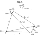
- an origin 202 defines an inertial reference frame.
- a GPS receiver 204 has true vector position r m and a GPS satellite 206 has an unknown true vector position, however an assumed vector position r ⁇ n is assigned as shown by 208.
- an initial estimate r ⁇ m is assigned as indicated by 210. The initial estimate might be found for example using a simple least-squares estimate of the receiver position, using code pseudorange measurements from a single GPS epoch only
- the common set of GPS measurements includes M base station reference receivers and N GPS satellites, such that each receiver in the common set has obtained GPS measurements for each satellite in the common set.
- Different common sets might be chosen for code pseudorange and ADR measurements, or for different GPS frequencies, so that the appropriate values of M and N and the appropriate common set should be used in each case.
- P ⁇ are the code pseudorange measurements
- ⁇ are the ADR measurements.
- r ⁇ n is the assumed vector position of satellite n
- r m is the true vector position of receiver m (expressed in an inertial frame of reference).
- ⁇ nmf is the ambiguity in the ADR measurement (an integer multiple of the corresponding carrier wavelength)
- ⁇ nmfP l A are errors, including measurement noise as well as spatially correlated errors. Errors in the assumed position of satellite n (ephemeris errors) are included in ⁇ nmfP l A .
- the random errors are reduced by the averaging process in forming the corrections, while the correlated errors take values typical of the base station as a whole.
- Equation 1.4 eliminates receiver clock errors, which have a large magnitude and which can vary significantly over time.
- the remaining errors in Equation 1.4 are relatively small, and so the removal of these receiver clock errors allows integrity monitoring of the GPS corrections.
- the reference receiver positions r ⁇ m can be accurately surveyed, and then ⁇ r ⁇ 0.
- the common set should be chosen so that this double-differenced ambiguity is available for all required channels.
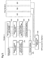
- Such a correction derivation with ambiguity compensation is illustrated in Figure 3 .
- ADR GPS measurements from each satellite in the common set are taken at 302.
- the expected satellite receiver separation is subtracted at 304, according to equation 1.2 to give component correction values, from which double differenced ambiguities are subtracted (and appropriate offsets added) at 306.
- the resulting values are averaged across all satellites in the set at 308, and the result provided at the negative input of 310.
- the ADR GPS measurement for satellite n undergoes a similar process as illustrated at 312 and 314, and is provided at the positive input of subtractor 310. The output of 310 is then provided to be averaged at 316.
- the ambiguity ⁇ nf in Equation 1.9 is constructed to be an integer multiple of the carrier wavelength (namely the ambiguity of the ADR measurements of receiver q 0 for the same satellite, offset by c nf ). Occasionally it will be necessary to change the pair ( p 0 , q 0 ), for example if the common set changes.
- c nf should be initialised to an integer multiple of the carrier wavelength (e.g. zero).
- the corrections are not all linearly independent. If necessary, the common components X fP and X fA can be removed by 'differencing' the corrections against a reference satellite before they are processed further
- ⁇ ⁇ a nmf u 0 ⁇ v 0 a nmf - a nv 0 ⁇ f - a u 0 ⁇ mf + a u 0 ⁇ v 0 ⁇ f are determined, for some choice of satellite-receiver reference channel ( u 0 , v 0 ), by an ambiguity filter as is known in the art, using GPS measurements from the reference receivers.
- a 'float' Kalman filter is run, with a state vector which includes the ambiguities and also parameters which represent correlated error states (e.g. atmospheric errors) and the receiver positions.
- the space of the double-differenced integer ambiguities (Equation 1.16) can be searched to find the most probable set of ambiguities.
- the probability that the chosen ambiguities are correct should be checked, to ensure that the solution meets any integrity requirements.
- the relative GPS filter uses the corrections, Equations 1.4 and 1.8, together with rover GPS measurements which are of the form of Equation 1.2. and combines the data in the form:
- the relative position of the rover GPS antenna and the centroid of the base station antennas can then be found by adding: r ⁇ rover - 1 M ⁇ m r ⁇ m base
- the common components X fP and X fA , and errors in the rover and base station measurements correlated between different satellites can be eliminated by differencing, i.e. identifying a reference satellite n 0 and forming
- An ambiguity resolution method can be used to 'fix' the ambiguity states to integer values, resulting in a very high accuracy relative position estimate.
- the position of the rover will be required relative to a desired reference point in the base station, rather than relative to the centroid of the base station GPS antennas.
- the aircraft position is required relative to the flight deck.
- the vectors or 'lever arms' between the reference point and the antennas can be determined, for example using knowledge of their relative position in the base station body frame of reference, and knowledge of the base station attitude using an inertial navigation system.
- these lever arms are liable to include errors, caused for example by errors in surveying the antenna positions, thermal expansion or flexure of the base station, and errors in the INS estimate of attitude. For example, considering an aircraft carrier deck over 200m long, an attitude error of 2 mrad over a lever arm length of 100m gives a positional error of approximately 20cm, which is highly significant on the scale of relative carrier phase GPS errors.
- the present invention affords a more straightforward solution.
- the GPS estimation and ambiguity fixing is completed, and the rover position estimated relative to the centroid of the base station receivers, before the lever arm information is introduced.
- the centroid is determined solely by the physical arrangement of base station receivers, and may not be a useful reference for a given application, such a relative position estimate can be free of 'lever arm' errors.
- the position relative to a desired reference point can be found subsequently, using the average of the reference receiver lever arms. Allowance must be made for the change in the position of the centroid if the base station common set changes, since the calculation of this change will be affected by the lever arm errors.
- GPS has been used as an example, it will be understood that the invention is applicable to any appropriate satellite based navigation system, either alone, or in conjunction with other measurement systems, for example inertial techniques.
- satellite measurements have been described, the skilled person will appreciate that other types of measurements subject to phase ambiguity, are equally applicable.
Landscapes
- Engineering & Computer Science (AREA)
- Radar, Positioning & Navigation (AREA)
- Remote Sensing (AREA)
- Computer Networks & Wireless Communication (AREA)
- Physics & Mathematics (AREA)
- General Physics & Mathematics (AREA)
- Position Fixing By Use Of Radio Waves (AREA)
- Magnetic Heads (AREA)
- Measurement Of Resistance Or Impedance (AREA)
- Measuring Phase Differences (AREA)
- Window Of Vehicle (AREA)
Claims (8)
- Verfahren zum Herleiten eines Korrekturwerts Anf für eine phasenbezogene Satellitennavigationsmessung für einen Satelliten n aus einem bekannten Satz von mehreren Basisstations-Referenzempfängern M und mehreren Satelliten N, dadurch gekennzeichnet, dass die Phasenungenauigkeit anf in dem von dem bekannten Satz hergeleiteten Korrekturwert Anf darauf beschränkt ist, ein ganzzahliges Vielfaches der Trägerwellenlänge λ zu sein, wobei Komponentenkorrekturwerte A'nmf über alle Basisstationsempfänger und alle Satelliten von dem bekannten Satz gemittelt sind, und wobei vor dem Mitteln von jedem Komponentenkorrekturwert doppelt differenziale Ungenauigkeiten λa subtrahiert werden.
- Verfahren nach Anspruch 1, das Folgendes aufweist:- Ermitteln eines Komponentenkorrekturwerts A'nmf zu jeder eines Satzes von Satellitenmessungen (304) bei jedem der Basisstations-Referenzempfänger, Subtrahieren von doppelt differenzialen Ungenauigkeiten δa von jedem der Komponentenwerte (306) und Mitteln (308) über alle Satelliten des Satzes, um einen ersten Zwischenwert zu erstellen,- Ermitteln eines Komponentenkorrekturwerts A'nmf zur Messung für Satellit n (312) bei jedem der Basisstations-Referenzempfänger, Subtrahieren der zu der Basisstation und zu dem Satellit n (314) gehörenden doppelt differenzialen Ungenauigkeit und Subtrahieren (310) des ersten Zwischenwerts, um einen zweiten Zwischenwert zu erstellen; und- Mitteln des zweiten Werts über jede Basisstation in einem Satz (316), um einen abschließenden Korrekturwert Anf zu erstellen.
- Verfahren nach Anspruch 1 oder Anspruch 2, worin die doppelt differenzialen Ungenauigkeiten δa durch ein ganzzahliges Vielfaches der Trägerwellenlänge cn beabstandet sind.
- Verfahren nach Anspruch 3, worin die doppelt differenzialen Ungenauigkeiten relativ zu einem ausgewählten Satellit-Empfänger-Referenzpaar p0q0 bestimmt werden, und worin die Phasenungenauigkeit anf im Korrekturwert gleich der Ungenauigkeit für den ausgewählten Referenzempfänger qo versetzt um eine Konstante cn ist.
- Verfahren nach Anspruch 4, worin die Konstante cn zum Kompensieren einer Änderung des Referenzpaares p0q0 eingestellt wird.
- Verfahren nach Anspruch 5, worin cn bei einem Wechsel des Referenzpaares poqo zum Referenzpaar p1q1 um die relativ zum Satellit-Empfänger-Referenzpaar p1q1 bestimmte doppelt differenziale Ungenauigkeit für den bisherigen Referenzempfänger q0 erhöht wird.
- Verfahren nach einem der vorhergehenden Ansprüche, worin der Phasenkorrekturwert bestimmt wird zu:

wobei:Anf den Phasenkorrekturwert für Satellit n bei der Frequenz f darstellt,M die Gesamtzahl der Basisstations-Referenzempfänger im bekannten Satz angibt,N die Gesamtzahl an Satelliten im bekannten Satz angibt, A'nmf der Komponentenkorrekturwert für Empfänger m für Satellit n bei der Frequenz f ist,die doppelt differenziale Referenzempfänger-Ungenauigkeit für Empfänger m für Satellit n bei der Frequenz f relativ zu einem ausgewählten Satelliten-Empfänger-Paar p0q0 ist,cnf ein ganzzahliges Vielfaches der Trägerwellenlänge ist. - Verfahren nach einem der vorhergehenden Ansprüche, worin der Korrekturwert zur Bestimmung einer geschätzten Position eines Objekts relativ zu einem Mittelwert der Positionen der Basisstationsempfänger verwendet wird, und worin die Schätzung anschließend transformiert wird, um relativ zu einem ausgewählten Basisstationsreferenzpunkt zu sein.
Applications Claiming Priority (2)
| Application Number | Priority Date | Filing Date | Title |
|---|---|---|---|
| GBGB0625244.9A GB0625244D0 (en) | 2006-12-19 | 2006-12-19 | GPS corrections |
| PCT/GB2007/004809 WO2008075002A1 (en) | 2006-12-19 | 2007-12-17 | Phase based measurement corrections |
Publications (2)
| Publication Number | Publication Date |
|---|---|
| EP2092362A1 EP2092362A1 (de) | 2009-08-26 |
| EP2092362B1 true EP2092362B1 (de) | 2012-04-18 |
Family
ID=37712360
Family Applications (1)
| Application Number | Title | Priority Date | Filing Date |
|---|---|---|---|
| EP07848550A Active EP2092362B1 (de) | 2006-12-19 | 2007-12-17 | Messungskorrekturen auf phasenbasis |
Country Status (7)
| Country | Link |
|---|---|
| US (1) | US8451880B2 (de) |
| EP (1) | EP2092362B1 (de) |
| AT (1) | ATE554407T1 (de) |
| AU (1) | AU2007336051B2 (de) |
| CA (1) | CA2672119C (de) |
| GB (1) | GB0625244D0 (de) |
| WO (1) | WO2008075002A1 (de) |
Families Citing this family (8)
| Publication number | Priority date | Publication date | Assignee | Title |
|---|---|---|---|---|
| PL2460059T3 (pl) | 2009-07-28 | 2018-12-31 | Bae Systems Plc | Szacowanie położeń urządzenia i co najmniej jednego celu w środowisku |
| US8659474B2 (en) * | 2011-01-12 | 2014-02-25 | Navcom Technology, Inc. | Navigation system and method for resolving integer ambiguities using double difference ambiguity constraints |
| US10473789B1 (en) * | 2015-04-13 | 2019-11-12 | Lockheed Martin Corporation | Real-time ship position error compensation system and method |
| US10782417B2 (en) | 2016-07-29 | 2020-09-22 | Trimble Inc. | Mobile reference station for GNSS positioning |
| CN106443631A (zh) * | 2016-11-15 | 2017-02-22 | 南京邮电大学 | 一种非平稳海杂波背景下子带分段anmf检测方法 |
| CN110971288B (zh) * | 2018-09-28 | 2022-04-15 | 海能达通信股份有限公司 | 一种定位方法及装置 |
| US10830905B2 (en) | 2018-11-16 | 2020-11-10 | Trimble Inc. | Vertical accuracy improvements for dynamic real-time kinematic reference stations |
| EP3899583A4 (de) * | 2019-01-05 | 2022-09-07 | Xco Tech Inc. | Verfahren zur korrektur der phasenmehrdeutigkeit in bereichs- und phasenmessungsübergängen |
Family Cites Families (10)
| Publication number | Priority date | Publication date | Assignee | Title |
|---|---|---|---|---|
| US4912475A (en) * | 1987-03-20 | 1990-03-27 | Massachusetts Institute Of Technology | Techniques for determining orbital data |
| US5147179A (en) * | 1989-12-08 | 1992-09-15 | Bransch Edward J | Turbine pump with multistage venting of lubricating fluid flow |
| US5148179A (en) | 1991-06-27 | 1992-09-15 | Trimble Navigation | Differential position determination using satellites |
| US5983161A (en) * | 1993-08-11 | 1999-11-09 | Lemelson; Jerome H. | GPS vehicle collision avoidance warning and control system and method |
| US5477458A (en) * | 1994-01-03 | 1995-12-19 | Trimble Navigation Limited | Network for carrier phase differential GPS corrections |
| US5519620A (en) * | 1994-02-18 | 1996-05-21 | Trimble Navigation Limited | Centimeter accurate global positioning system receiver for on-the-fly real-time kinematic measurement and control |
| US5570097A (en) * | 1995-08-11 | 1996-10-29 | Northrop Grumman Corporation | Retransmitted GPS interferometric system |
| US6067852A (en) * | 1997-08-26 | 2000-05-30 | University Corporation For Atmospheric Research | Method and apparatus using slant-path water delay estimates to correct global positioning satellite survey error |
| US6567041B1 (en) * | 2001-04-18 | 2003-05-20 | Sprint Spectrum, L.P. | Network system and method for a remote reference receiver system |
| US6832155B2 (en) * | 2002-09-23 | 2004-12-14 | Itt Manufacturing Enterprises, Inc. | Methods and apparatus for determining phase ambiguities in ranging and navigation systems |
-
2006
- 2006-12-19 GB GBGB0625244.9A patent/GB0625244D0/en not_active Ceased
-
2007
- 2007-12-17 CA CA2672119A patent/CA2672119C/en active Active
- 2007-12-17 AU AU2007336051A patent/AU2007336051B2/en active Active
- 2007-12-17 EP EP07848550A patent/EP2092362B1/de active Active
- 2007-12-17 AT AT07848550T patent/ATE554407T1/de active
- 2007-12-17 US US12/517,825 patent/US8451880B2/en active Active
- 2007-12-17 WO PCT/GB2007/004809 patent/WO2008075002A1/en not_active Ceased
Also Published As
| Publication number | Publication date |
|---|---|
| CA2672119C (en) | 2016-07-19 |
| EP2092362A1 (de) | 2009-08-26 |
| AU2007336051A1 (en) | 2008-06-26 |
| ATE554407T1 (de) | 2012-05-15 |
| AU2007336051B2 (en) | 2011-07-07 |
| CA2672119A1 (en) | 2008-06-26 |
| US8451880B2 (en) | 2013-05-28 |
| GB0625244D0 (en) | 2007-01-24 |
| WO2008075002A1 (en) | 2008-06-26 |
| US20100166044A1 (en) | 2010-07-01 |
Similar Documents
| Publication | Publication Date | Title |
|---|---|---|
| US10976444B2 (en) | System and method for GNSS ambiguity resolution | |
| EP2156214B1 (de) | Trägerphasensichere mehrdeutigkeitsauflösung bei einer teilsuche | |
| US7961143B2 (en) | Partial search carrier-phase integer ambiguity resolution | |
| US6424914B1 (en) | Fully-coupled vehicle positioning method and system thereof | |
| JP5305416B2 (ja) | 衛星航法システムにおける電離圏異常を検出する方法及びその装置。 | |
| US5757316A (en) | Attitude determination utilizing an inertial measurement unit and a plurality of satellite transmitters | |
| US6760663B2 (en) | Solution separation method and apparatus for ground-augmented global positioning system | |
| US6496778B1 (en) | Real-time integrated vehicle positioning method and system with differential GPS | |
| EP2380036B1 (de) | Navigationsempfänger und verfahren zur kombinierten verwendung eines rtk-standardsystems und carrier-phase-dgps | |
| AU2015227414B2 (en) | Precise GNSS positioning system with improved ambiguity estimation | |
| US8451880B2 (en) | Phase based measurement corrections | |
| US6127968A (en) | On-the-fly RTK positioning system with single frequency receiver | |
| US7098846B2 (en) | All-weather precision guidance and navigation system | |
| EP2663878B1 (de) | Navigationssystem und verfahren für die auflösung von ganzzahligen mehrdeutigkeiten mit doppeldifferenzierten mehrdeutigkeitsbeschränkungen | |
| WO2023167899A1 (en) | System and method for fusing sensor and satellite measurements for positioning determination | |
| US20130090858A1 (en) | System for measuring coseismic movements or vibrations of structures based on global navigation satellite systems-gnss and/or pseudolites | |
| Han et al. | Robust GPS/BDS/INS tightly coupled integration with atmospheric constraints for long-range kinematic positioning | |
| WO2024050094A1 (en) | System and method for determining gnss corrections | |
| JP7497119B2 (ja) | 測位装置 | |
| CN120891529A (zh) | 一种基于单北斗导航与高精度rtk技术融合的定位方法、装置、介质及设备 | |
| RU2624268C1 (ru) | Способ определения взаимного положения объектов по сигналам глобальных навигационных спутниковых систем | |
| CN114397684B (zh) | 模糊度的固定方法及相关设备 | |
| El-Mowafy et al. | Attitude determination from GNSS using adaptive Kalman filtering | |
| CN115327596A (zh) | 一种利用道路平面约束rtk定位的方法 | |
| Offer et al. | Use of inertial integration to enhance availability for shipboard relative GPS (SRGPS) |
Legal Events
| Date | Code | Title | Description |
|---|---|---|---|
| PUAI | Public reference made under article 153(3) epc to a published international application that has entered the european phase |
Free format text: ORIGINAL CODE: 0009012 |
|
| 17P | Request for examination filed |
Effective date: 20090609 |
|
| AK | Designated contracting states |
Kind code of ref document: A1 Designated state(s): AT BE BG CH CY CZ DE DK EE ES FI FR GB GR HU IE IS IT LI LT LU LV MC MT NL PL PT RO SE SI SK TR |
|
| RIN1 | Information on inventor provided before grant (corrected) |
Inventor name: OFFER, CHARLES ROBERT |
|
| 17Q | First examination report despatched |
Effective date: 20091216 |
|
| DAX | Request for extension of the european patent (deleted) | ||
| RAP1 | Party data changed (applicant data changed or rights of an application transferred) |
Owner name: QINETIQ LIMITED |
|
| REG | Reference to a national code |
Ref country code: DE Ref legal event code: R079 Ref document number: 602007022158 Country of ref document: DE Free format text: PREVIOUS MAIN CLASS: G01S0001000000 Ipc: G01S0019440000 |
|
| RIC1 | Information provided on ipc code assigned before grant |
Ipc: G01S 19/07 20100101ALI20110816BHEP Ipc: G01S 19/04 20100101ALI20110816BHEP Ipc: G01S 19/44 20100101AFI20110816BHEP Ipc: G01S 19/41 20100101ALI20110816BHEP |
|
| GRAP | Despatch of communication of intention to grant a patent |
Free format text: ORIGINAL CODE: EPIDOSNIGR1 |
|
| GRAS | Grant fee paid |
Free format text: ORIGINAL CODE: EPIDOSNIGR3 |
|
| GRAA | (expected) grant |
Free format text: ORIGINAL CODE: 0009210 |
|
| AK | Designated contracting states |
Kind code of ref document: B1 Designated state(s): AT BE BG CH CY CZ DE DK EE ES FI FR GB GR HU IE IS IT LI LT LU LV MC MT NL PL PT RO SE SI SK TR |
|
| REG | Reference to a national code |
Ref country code: GB Ref legal event code: FG4D |
|
| REG | Reference to a national code |
Ref country code: CH Ref legal event code: EP |
|
| REG | Reference to a national code |
Ref country code: IE Ref legal event code: FG4D |
|
| REG | Reference to a national code |
Ref country code: AT Ref legal event code: REF Ref document number: 554407 Country of ref document: AT Kind code of ref document: T Effective date: 20120515 |
|
| REG | Reference to a national code |
Ref country code: DE Ref legal event code: R096 Ref document number: 602007022158 Country of ref document: DE Effective date: 20120614 |
|
| REG | Reference to a national code |
Ref country code: NL Ref legal event code: VDEP Effective date: 20120418 |
|
| REG | Reference to a national code |
Ref country code: AT Ref legal event code: MK05 Ref document number: 554407 Country of ref document: AT Kind code of ref document: T Effective date: 20120418 |
|
| LTIE | Lt: invalidation of european patent or patent extension |
Effective date: 20120418 |
|
| PG25 | Lapsed in a contracting state [announced via postgrant information from national office to epo] |
Ref country code: SE Free format text: LAPSE BECAUSE OF FAILURE TO SUBMIT A TRANSLATION OF THE DESCRIPTION OR TO PAY THE FEE WITHIN THE PRESCRIBED TIME-LIMIT Effective date: 20120418 Ref country code: LT Free format text: LAPSE BECAUSE OF FAILURE TO SUBMIT A TRANSLATION OF THE DESCRIPTION OR TO PAY THE FEE WITHIN THE PRESCRIBED TIME-LIMIT Effective date: 20120418 Ref country code: IS Free format text: LAPSE BECAUSE OF FAILURE TO SUBMIT A TRANSLATION OF THE DESCRIPTION OR TO PAY THE FEE WITHIN THE PRESCRIBED TIME-LIMIT Effective date: 20120818 Ref country code: CY Free format text: LAPSE BECAUSE OF FAILURE TO SUBMIT A TRANSLATION OF THE DESCRIPTION OR TO PAY THE FEE WITHIN THE PRESCRIBED TIME-LIMIT Effective date: 20120418 Ref country code: FI Free format text: LAPSE BECAUSE OF FAILURE TO SUBMIT A TRANSLATION OF THE DESCRIPTION OR TO PAY THE FEE WITHIN THE PRESCRIBED TIME-LIMIT Effective date: 20120418 Ref country code: PL Free format text: LAPSE BECAUSE OF FAILURE TO SUBMIT A TRANSLATION OF THE DESCRIPTION OR TO PAY THE FEE WITHIN THE PRESCRIBED TIME-LIMIT Effective date: 20120418 |
|
| PG25 | Lapsed in a contracting state [announced via postgrant information from national office to epo] |
Ref country code: GR Free format text: LAPSE BECAUSE OF FAILURE TO SUBMIT A TRANSLATION OF THE DESCRIPTION OR TO PAY THE FEE WITHIN THE PRESCRIBED TIME-LIMIT Effective date: 20120719 Ref country code: LV Free format text: LAPSE BECAUSE OF FAILURE TO SUBMIT A TRANSLATION OF THE DESCRIPTION OR TO PAY THE FEE WITHIN THE PRESCRIBED TIME-LIMIT Effective date: 20120418 Ref country code: SI Free format text: LAPSE BECAUSE OF FAILURE TO SUBMIT A TRANSLATION OF THE DESCRIPTION OR TO PAY THE FEE WITHIN THE PRESCRIBED TIME-LIMIT Effective date: 20120418 Ref country code: PT Free format text: LAPSE BECAUSE OF FAILURE TO SUBMIT A TRANSLATION OF THE DESCRIPTION OR TO PAY THE FEE WITHIN THE PRESCRIBED TIME-LIMIT Effective date: 20120820 |
|
| PG25 | Lapsed in a contracting state [announced via postgrant information from national office to epo] |
Ref country code: BE Free format text: LAPSE BECAUSE OF FAILURE TO SUBMIT A TRANSLATION OF THE DESCRIPTION OR TO PAY THE FEE WITHIN THE PRESCRIBED TIME-LIMIT Effective date: 20120418 |
|
| PG25 | Lapsed in a contracting state [announced via postgrant information from national office to epo] |
Ref country code: RO Free format text: LAPSE BECAUSE OF FAILURE TO SUBMIT A TRANSLATION OF THE DESCRIPTION OR TO PAY THE FEE WITHIN THE PRESCRIBED TIME-LIMIT Effective date: 20120418 Ref country code: CZ Free format text: LAPSE BECAUSE OF FAILURE TO SUBMIT A TRANSLATION OF THE DESCRIPTION OR TO PAY THE FEE WITHIN THE PRESCRIBED TIME-LIMIT Effective date: 20120418 Ref country code: SK Free format text: LAPSE BECAUSE OF FAILURE TO SUBMIT A TRANSLATION OF THE DESCRIPTION OR TO PAY THE FEE WITHIN THE PRESCRIBED TIME-LIMIT Effective date: 20120418 Ref country code: AT Free format text: LAPSE BECAUSE OF FAILURE TO SUBMIT A TRANSLATION OF THE DESCRIPTION OR TO PAY THE FEE WITHIN THE PRESCRIBED TIME-LIMIT Effective date: 20120418 Ref country code: DK Free format text: LAPSE BECAUSE OF FAILURE TO SUBMIT A TRANSLATION OF THE DESCRIPTION OR TO PAY THE FEE WITHIN THE PRESCRIBED TIME-LIMIT Effective date: 20120418 Ref country code: NL Free format text: LAPSE BECAUSE OF FAILURE TO SUBMIT A TRANSLATION OF THE DESCRIPTION OR TO PAY THE FEE WITHIN THE PRESCRIBED TIME-LIMIT Effective date: 20120418 Ref country code: EE Free format text: LAPSE BECAUSE OF FAILURE TO SUBMIT A TRANSLATION OF THE DESCRIPTION OR TO PAY THE FEE WITHIN THE PRESCRIBED TIME-LIMIT Effective date: 20120418 |
|
| PLBE | No opposition filed within time limit |
Free format text: ORIGINAL CODE: 0009261 |
|
| STAA | Information on the status of an ep patent application or granted ep patent |
Free format text: STATUS: NO OPPOSITION FILED WITHIN TIME LIMIT |
|
| PG25 | Lapsed in a contracting state [announced via postgrant information from national office to epo] |
Ref country code: IT Free format text: LAPSE BECAUSE OF FAILURE TO SUBMIT A TRANSLATION OF THE DESCRIPTION OR TO PAY THE FEE WITHIN THE PRESCRIBED TIME-LIMIT Effective date: 20120418 |
|
| 26N | No opposition filed |
Effective date: 20130121 |
|
| PG25 | Lapsed in a contracting state [announced via postgrant information from national office to epo] |
Ref country code: ES Free format text: LAPSE BECAUSE OF FAILURE TO SUBMIT A TRANSLATION OF THE DESCRIPTION OR TO PAY THE FEE WITHIN THE PRESCRIBED TIME-LIMIT Effective date: 20120729 |
|
| REG | Reference to a national code |
Ref country code: DE Ref legal event code: R097 Ref document number: 602007022158 Country of ref document: DE Effective date: 20130121 |
|
| PG25 | Lapsed in a contracting state [announced via postgrant information from national office to epo] |
Ref country code: MC Free format text: LAPSE BECAUSE OF NON-PAYMENT OF DUE FEES Effective date: 20121231 Ref country code: BG Free format text: LAPSE BECAUSE OF FAILURE TO SUBMIT A TRANSLATION OF THE DESCRIPTION OR TO PAY THE FEE WITHIN THE PRESCRIBED TIME-LIMIT Effective date: 20120718 |
|
| REG | Reference to a national code |
Ref country code: CH Ref legal event code: PL |
|
| REG | Reference to a national code |
Ref country code: IE Ref legal event code: MM4A |
|
| PG25 | Lapsed in a contracting state [announced via postgrant information from national office to epo] |
Ref country code: LI Free format text: LAPSE BECAUSE OF NON-PAYMENT OF DUE FEES Effective date: 20121231 Ref country code: IE Free format text: LAPSE BECAUSE OF NON-PAYMENT OF DUE FEES Effective date: 20121217 Ref country code: CH Free format text: LAPSE BECAUSE OF NON-PAYMENT OF DUE FEES Effective date: 20121231 |
|
| PG25 | Lapsed in a contracting state [announced via postgrant information from national office to epo] |
Ref country code: MT Free format text: LAPSE BECAUSE OF FAILURE TO SUBMIT A TRANSLATION OF THE DESCRIPTION OR TO PAY THE FEE WITHIN THE PRESCRIBED TIME-LIMIT Effective date: 20120418 |
|
| PG25 | Lapsed in a contracting state [announced via postgrant information from national office to epo] |
Ref country code: TR Free format text: LAPSE BECAUSE OF FAILURE TO SUBMIT A TRANSLATION OF THE DESCRIPTION OR TO PAY THE FEE WITHIN THE PRESCRIBED TIME-LIMIT Effective date: 20120418 |
|
| PG25 | Lapsed in a contracting state [announced via postgrant information from national office to epo] |
Ref country code: LU Free format text: LAPSE BECAUSE OF NON-PAYMENT OF DUE FEES Effective date: 20121217 |
|
| PG25 | Lapsed in a contracting state [announced via postgrant information from national office to epo] |
Ref country code: HU Free format text: LAPSE BECAUSE OF FAILURE TO SUBMIT A TRANSLATION OF THE DESCRIPTION OR TO PAY THE FEE WITHIN THE PRESCRIBED TIME-LIMIT Effective date: 20071217 |
|
| REG | Reference to a national code |
Ref country code: FR Ref legal event code: PLFP Year of fee payment: 9 |
|
| REG | Reference to a national code |
Ref country code: FR Ref legal event code: PLFP Year of fee payment: 10 |
|
| REG | Reference to a national code |
Ref country code: FR Ref legal event code: PLFP Year of fee payment: 11 |
|
| P01 | Opt-out of the competence of the unified patent court (upc) registered |
Effective date: 20230401 |
|
| PGFP | Annual fee paid to national office [announced via postgrant information from national office to epo] |
Ref country code: GB Payment date: 20251229 Year of fee payment: 19 |
|
| PGFP | Annual fee paid to national office [announced via postgrant information from national office to epo] |
Ref country code: FR Payment date: 20251226 Year of fee payment: 19 |
|
| PGFP | Annual fee paid to national office [announced via postgrant information from national office to epo] |
Ref country code: DE Payment date: 20251229 Year of fee payment: 19 |