EP2092385B1 - Beleuchtungsquelle für mikroskope mit lichtemittierenden dioden für gefärbte biologische proben - Google Patents
Beleuchtungsquelle für mikroskope mit lichtemittierenden dioden für gefärbte biologische proben Download PDFInfo
- Publication number
- EP2092385B1 EP2092385B1 EP07854894.8A EP07854894A EP2092385B1 EP 2092385 B1 EP2092385 B1 EP 2092385B1 EP 07854894 A EP07854894 A EP 07854894A EP 2092385 B1 EP2092385 B1 EP 2092385B1
- Authority
- EP
- European Patent Office
- Prior art keywords
- led
- leds
- light
- green
- red
- Prior art date
- Legal status (The legal status is an assumption and is not a legal conclusion. Google has not performed a legal analysis and makes no representation as to the accuracy of the status listed.)
- Active
Links
Images



Classifications
-
- G—PHYSICS
- G02—OPTICS
- G02B—OPTICAL ELEMENTS, SYSTEMS OR APPARATUS
- G02B21/00—Microscopes
- G02B21/06—Means for illuminating specimens
- G02B21/08—Condensers
- G02B21/086—Condensers for transillumination only
Definitions
- the field of the invention generally relates to the field of cytology and histology. More specifically, the field of the invention relates to devices and methods for illuminating stained biological samples using one or more light emitting diodes (LEDs).
- LEDs light emitting diodes
- Incandescent lamps produce white light that is a combination of all colors in the visible spectrum (from about 400 nm to about 700 nm). Unfortunately, incandescent lamps produce considerable heat, have low energy efficiency, and must often be replaced frequently.
- LEDs Light emitting diodes
- S-cones S-cones
- M-cones M-cones
- L-cones S-cones
- S-cones S-cones
- M-cones M-cones
- L-cones S-cones
- S-cones S-cones
- M-cones M-cones
- L-cones S-cones
- All three types of cone cells are sensitive to a wideband of wavelengths, but have different peak sensitivities. For example, S-cones are most sensitive around 420 nm (blue) while M-cones are sensitive around 534 nm (green), and L-cones are sensitive around 564 nm (red).
- the eye essentially integrates the spectral function, producing three signals. One signal is the light intensity. Another differentiates blue light from yellow. Finally, the third separates yellow into red or green light. This integration of the spectrum averages colors together. Light from a yellow LED (590 nm) will appear the same to the eye as light from green and red LEDs combined (530 nm and 650 nm), because in both cases red and green are balanced and outweigh blue.
- a microscope illumination system that uses separate colored red, green, and blue LEDs can be tuned to any color of illumination, depending on the operator's preferences.
- white light such as the light emitted from conventional incandescent bulbs is needed to illuminate the biological sample.
- Pathologists and others trained in viewing biological samples for disease states are familiar with analyzing samples illuminated with a broadband, incandescent light source.
- LEDs to imitate the white light emitted from conventional incandescent sources.
- single LEDs have been produced that generate a mixture of colored light to approximate white light.
- blue light is emitted from a gallium nitride diode semiconductor (at around 460 nm).
- Secondary light in the range of about 550 nm to around 650 nm is emitted by a phosphor coating located inside a polymer jacket.
- the combination of wavelengths produces "white" light having a relatively high color temperature.
- a problem with LEDs of the type described above is that they are not good at producing light at relatively long wavelengths (e.g., red light).
- light from red, green and blue LEDs is combined to produce illumination which appears to be white, but does not contain the full visible spectrum.
- the intensity of the illumination in the yellow band (around 565 nm to 590 nm) is very low.
- This gap in the yellow portion of the spectrum causes some stained cell samples to appear to be a different color than if they were illuminated with an incandescent lamp. This is problematic because the stained biological sample will appear different to a pathologist or other trained individual under the LED-based white light as compared to conventional incandescent white light.
- Pathologists are typically trained on microscopes that use broadband incandescent light sources. Different visual appearances may lead to confusion and misinterpretation of slide results.
- US 2003/042493 A1 discloses a solid-state light source comprising a semiconductor light source for emitting light and an optical system having a fiber optic element.
- the fiber optic element has an input for receiving emitted light from the semiconductor light source.
- the fiber optic element also has an output for emitting light received from the solid-state light source.
- the semiconductor light source and the fiber optic element in aggregate form an illumination path.
- DE 199 62 779 A1 discloses a device having a first optical unit with at least one illumination unit having at least one light diode to direct visible red, green and blue light at a given angle to a surface to be measured.
- a second optical unit at a given angle to the surface has at least one photosensor to detect light reflected from the surface.
- a filter unit is arranged between the light diodes and the photosensor.
- a control and evaluation unit controls the measurement process and evaluates at least one characteristic of the reflected light, to characterise the surface.
- the control and evaluation unit has at least one processor unit and at least one memory unit.
- EP 1510847 A1 discloses a microscope having a top illumination device integrated into the structure of a microscope with at least one light emitting diode that emits white light, illumination optics and a deflection element arranged so that the object plane can be illuminated with the illumination light by the coaxial top illumination method.
- EP 1150154 A1 discloses an illumination system comprising several concentric rings of white light LEDs with small angle of radiation fixed in a ring carrier.
- the LEDs in the ring rows have the same lateral distance under each other.
- the LEDs are controllable individually or in groups and-or are regulatable regarding brightness.
- the LEDs are connected in groups in series, so that each group is assigned a controllable constant current source, which is connected respectively with an output of a digital-analogue converter.
- GB 2348968 A discloses an illuminated magnifier having a lens held in place by a lens support.
- An LED is secured to the lens support in such a way that the LED illuminates an area being viewed by the lens.
- the LED can be in the form of an array and may be supported by an LED support, which in turn can be removably securable to the lens support.
- the LED can be a wide angle high intensity LED.
- a power supply to power the LED may also be included and the LED may also be connected to a control circuit by means of an electric conductor.
- US 2005/231713 A1 discloses a camera, light sources, lenses and software algorithms used to image and inspect semiconductor structures, including through infrared radiation. Also described is the use of various configurations of solid state lighting and software algorithms enhances the imaging and inspection.
- a first aspect of the invention provides a microscope illumination system in accordance with claim 1.
- Each of the at least four LED light sources may be independently controllable.
- the resultant light emitted from the at least four LED sources substantially approximates that from an incandescent light source.
- the at least four LED sources may be any color that, when combined, closely imitates light emitted from an incandescent or broadband light source.
- the illumination system may include a plurality of LEDs of each color.
- the illumination system may comprise a single red, green, and blue LED and multiple yellow LEDs. Still other color combinations are possible.
- the four LED colors may include violet, cyan, yellow-green, and orange.
- the illumination system includes one or more driving circuits operably connected to the four colors of LEDs.
- a first circuit may be used to drive the RGB colors while a second circuit may be used to drive the yellow LED.
- each color red, green, blue, and yellow
- each color may be controlled by individual circuits.
- the brightness of the individual colored LEDs can be independently controlled.
- the four colored LEDs may be separate or they be integrated into a single or multiple modules.
- the RGB LEDs may be in one module while the yellow LEDs are located in a separate module.
- FIG. 1 schematically illustrates a microscope illumination system 10.
- the microscope illumination system 10 includes an illumination or light source 12 that includes at least four separate LEDs.
- the LEDs include at least one red LED, at least one green LED, at least one blue LED, and at least one yellow LED.
- the colors referenced above refer to the color of light emitted from the respective LED.
- the red LED generally emits light within the range of about 625 nm to about 660 nm.
- the green LED generally emits light within the range of about 480 nm to about 575 nm.
- the blue LED generally emits light within the range of about 450 nm to about 500 nm.
- the yellow LED generally emits light within the range of about 575 nm to about 625 nm.
- these ranges are meant to encompass the bulk of light transmitted from each respective LED and some emissions beyond the stated range are expected to occur.
- the addition of the yellow LED fills a gap in the emission spectrum from the microscope illumination system 10 if just red, green, and blue LEDs were used as the illumination source.
- the addition of the yellow LED allows the appearance of biological samples viewed under the LED-based microscope illumination system to more closely resemble the same samples viewed under the conventional incandescent system.
- pathologists and other trained professionals are able to better visualize certain structures and aspects of the biological sample. For example, when certain stains such as Eosin Y and orange G stain are used, cells and cellular structures illuminated with only RGB (red, blue, green) light from LEDs appear visually different to a user compared to the same objects illuminated with a conventional broadband, incandescent light source. The addition of the yellow LED diminishes this problem.
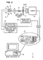
- an microscope illumination system 10 is to provide a "white" light source for imaging a biological (e.g., cytological) specimen 12 on a microscope slide 14 using a plurality of different color LEDs 16.
- the illumination source includes at least one red LED 16R, at least one green LED 16G, at least one blue LED 16B, and at least one yellow LED 16Y.
- Each LED 16 may be a high brightness LED such that a bright, white light is able to illuminate the biological specimen 12 for visualization.
- the plurality of LEDs may formed from a combination of single discrete LEDs, or custom multi-die LED-based module.
- the individual LEDs may be assembled to form an illumination subassembly from off-the-shelf components.
- an LED-based module in which individual LED dies are mounted on a common substrate 18 (as shown in FIGS. 1 and 2 ) may be used.
- the LEDs 16 generate heat, and as the temperature of an LED increases, the output wavelengths shift. The amount of heat generated depends on the current at which the LED is driven and the duration of time for which the current is applied.
- the LEDs 16 may be driven with a pulse circuit 20 that, in certain embodiments, is synchronized with a camera 22 of the imaging system 10 to deliver short, intense pulses of light to the camera 22 during the camera integration period.
- the camera 22 magnifies and captures images of the biological specimen 12 for subsequent viewing and/or analysis.
- the LEDs 16 do not have to be synchronized with the camera 22 if, for example, the microscope illumination system 10 was used by a human operator.
- the camera 22 may be replaced with conventional magnification optics (e.g., objective lenses and the like). In this application, the LEDs 16 would be powered continually - there is no need for synchronization.
- the LED pulse is synchronized with the camera frame integration by providing a external trigger that triggers both the camera/frame grabber 24 and the LED pulse driver 20, for example, using a square wave generator 26.
- the camera 22 does not respond instantaneously to the trigger.
- the pulse drive circuit 20 has a programmable delay that is used to synchronize the systems.
- other synchronization methods are possible, depending on the camera type and actual implementation.
- the illumination system 10 may include a processor 29 such as a personal computer that can be utilized to control the acquisition and storage of images taken via the camera 22.
- the processor 29 may coordinate various functions of the imaging sequence and also retain or transmit digital images of the biological specimens 12.
- LEDs 16 inherently produce spatially non-uniform light output and some optical applications require reasonably uniform illumination of the sample. For situations where uniformity is an issue, two types of systems for generating spatially uniform illumination may be used with LEDs 16, namely, Koehler and fiber optic systems.
- the LEDs 16 used in either of these systems may be discrete LEDs 16 packaged in close proximity or multiple LED 16 dies may be integrated on a single substrate 18 to produce a more dense arrangement.
- Koehler illumination is a standard technique for producing uniform illumination of a microscope slide 14 from the spatially non-uniform filament of an incandescent lamp used in traditional microscope illuminators. As determined by testing, this technique is equally effective at achieving uniformity when employed with LEDs 16.
- individual LEDs 16 are packaged closely together and placed in the general position of the lamp filament in the traditional Koehler illuminator 28.
- multiple LEDs 16 are coupled into a large core (around 500 to 600 ⁇ m) optical fiber 30 with lenses or other optical apparatus.
- U.S. Patent No. 6,665,060 which is incorporated by reference as if set forth fully herein discloses lenses that may be used with the LEDs 16.
- the length of the fiber 30 is selected so that the spatial non-uniformities of the LEDs 16 are mixed together and a relatively uniform spatial output from the fiber 30 is achieved.
- the output of the fiber 30 is approximately Gaussian in spatial profile.
- the fiber 30 may have to be displaced from the microscope slide 14, such that only the central, relatively flat, portion of the output is used.
- multiple LED dies may be placed on a single substrate 18.
- Individual lenses can be placed above each die so that the radiation from each die is collected into a narrow cone.
- the Koehler illuminator 28, 30 may be omitted entirely.
- the yellow LED 16Y in FIGS. 1 and 2 fills a gap in the emission spectrum of emitted light using RGB LEDs 16R, 16G, 16B.
- the intensity of illumination in the yellow region of the spectrum (about 565 nm to about 590 nm) is filled by the presence of the at least one yellow LED 16Y.
- FIGS. 1 and 2 illustrate a single yellow LED 16Y, in some embodiments multiple yellow LEDs 16Y may be used.
- a plurality of yellow LEDs 16Y encircle or surround an interior portion that contains RGB LEDs 16R, 16G, 16B or LED dies (see e.g., FIG. 4 ).
- the plurality of LEDs 16R, 16G, 16B, and 16Y are driven by separate driver circuits. That is to say, the at least one red LED 16R is driven by a first driving circuit 40R, the at least one green LED 16G is driven by a second, separate driving circuit 40G, the at least one blue LED 16B is driven by a third, separate driving circuit 40B, and the at least one yellow LED 16Y is driven by a fourth, separate driving circuit 40Y.
- FIG. 3 illustrates this embodiment wherein a separate driving circuit 40R, 40G, 40B, 40Y is associated with each respective LED 16R, 16G, 16B, and 16Y.
- the driving circuit 40R, 40G, 40B, 40Y typically includes a current source for applying electrical current to the LEDs 16R, 16G, 16B, and 16Y. Light is emitted from the diode when the current is forward-biased across the LED p-n junction.
- the driving circuits 40R, 40G, 40B, 40Y are capable of adjusting the brightness of each LED 16R, 16G, 16B, and 16Y independently of one another. For example, the brightness of the yellow LED 16Y may be adjusted independent of the red, green, and blue LEDs 16R, 16G, 16B. Brightness levels are adjusted using pulse width modulation.
- pulse width modulation is a known method for controlling LED brightness levels.
- the driving circuits 40R, 40G, 40B, 40Y may be implemented using one or more microprocessors.
- FIGS. 4 and 5 illustrate two exemplary configurations for an LED-based light source 50 for the illumination system 10.
- a series of yellow LEDs 16Y surround a LED module 42 having red, green, and blue LEDs 16R, 16G, 16B.
- the yellow LEDs 16Y are arranged in a symmetrical manner about the LED module 42.
- FIG. 5 which does not form part of the invention, illustrates another configuration of an LED-based light source 50 in which a module 42 containing red, green, and blue LEDs 16R, 16G, 16B emits radiation into a beam splitter BS.
- a separate module 42 containing a yellow LED 16Y is positioned generally perpendicular to the optical path of the RGB module 42 such that the yellow light emitted from the yellow LED 16Y is combined or merged with the red, green, and blue light transmitted through the beam splitter.
- the LED-base light sources 50 of FIGS. 4 and 5 are illustrative and other configurations combining red, green, blue, and yellow LEDs 16R, 16G, 16B, and 16Y are contemplated within the invention.
- FIG, 6 illustrates the spectrum of an illumination system 10 that uses red, green, blue, and yellow LEDs 16R, 16G, 16B, and 16Y.
- This fourth (i.e., yellow) color makes stained biological samples (e.g., cells) appear to be much closer to the colors perceived if the samples were illuminated with a broadband, incandescent light source.
- the invention is of particular interest for stained biological samples that use biological stains such as Eosin Y (C20H6Br4Na205; CAS No.
- Eosin Y absorbs a narrow band of light, with an absorption peak at around 525 nm. This absorption peak corresponds, almost exactly, with the peak emission wavelength of the green LED 16G.
- FIG. 7 illustrates the absorption spectrum for Eosin Y superimposed on the illumination spectra for the four color LEDs 16R, 16G, 16B, and 16Y ( FIG. 6 ). Note that for a sample stained with Eosin Y, most of the green light is blocked while the blue, yellow and red wavelengths are transmitted.
- LED-illuminated biological structures e.g., cells and cellular organelles
- incandescent light sources typically used in microscopes. If only RGB LEDs were used to illuminate cells, it is possible that a sample may be misdiagnosed by a pathologist or cytotechnologist because of the different appearances.
- the improved white illumination can be achieved by building an LED module 42 that incorporates one or more yellow LEDs 16Y in addition to one or more of the conventional red, green and blue LEDs 16R, 16G, 16B.
- multiple LED modules 42 may be combined to imitate a broadband, incandescent light source. While the invention described herein has been described using a four colors of LEDs (red, green, blue, and yellow), similar results could be achieved by any combination of colors of LEDs that covers enough of the visible spectrum. For example, a combination of violet, cyan, yellow-green, and orange LEDs would provide a spectrum just as full as that created by red, green, blue, and yellow LEDs. Inclusion of additional colors of LEDs in an illumination system 10 of the type described herein may be able to provide a more complete, fuller spectrum that emulates the spectrum emitted from incandescent radiation.
Landscapes
- Physics & Mathematics (AREA)
- Chemical & Material Sciences (AREA)
- Analytical Chemistry (AREA)
- General Physics & Mathematics (AREA)
- Optics & Photonics (AREA)
- Microscoopes, Condenser (AREA)
- Investigating Or Analysing Materials By Optical Means (AREA)
- Non-Portable Lighting Devices Or Systems Thereof (AREA)
Claims (5)
- Mikroskopbeleuchtungssystem (10) umfassend:eine Lichtquelle, die mindestens eine rote LED (16R), die ausgebildet ist, um Licht innerhalb eines Bereiches von 625 nm bis 660 nm zu emittieren, mindestens eine grüne LED (16G), die ausgebildet ist, um Licht innerhalb eines Bereiches von 480 nm bis 575 nm zu emittieren, mindestens eine blaue LED (16B), die ausgebildet ist, um Licht innerhalb eines Bereiches von 450 nm bis etwa 500 nm zu emittieren, und eine Vielzahl von gelben LEDs (16Y), die die mindestens eine rote LED (16R), und die mindestens eine grüne LED (16G), die mindestens eine blaue LED (16B) umschließen, umfasst, die Vielzahl von gelben LEDs (16Y) sind ausgebildet, um Licht innerhalb eines Bereiches von 575 nm bis 625 nm zu emittieren;einen Probenhalter, der innerhalb des Strahlenganges der Lichtquelle angeordnet ist, der Probenhalter ist ausgebildet, um einen Objektträger (14), der eine biologische Probe (12) enthält, zu halten;eine Kamera (22), die ausgebildet ist, um ein Bild der biologischen Probe (12) aufzunehmen und zu vergrößern;eine LED-Impulsansteuerungsschaltung (20), die ausgebildet ist, um die mindestens eine rote LED (16R), die mindestens eine grüne LED (16G), die mindestens eine blaue LED (16B), und die Vielzahl von gelben LEDs (16Y) gleichzeitig anzusteuern, so dass die LEDs (16R, 16G, 16B, 16Y) gleichzeitig angeschaltet werden; undeinen externen Auslöser (26), der ausgebildet ist, um die LED-Impulsansteuerungsschaltung (20) auszulösen, um während eines Integrationszeitraums der Kamera kurze, starke Lichtimpulse an die Kamera (22) abzugeben.
- Mikroskopbeleuchtungssystem (10) gemäß Anspruch 1, wobei die mindestens eine rote LED (16R), die mindestens eine grüne LED (16G), die mindestens eine blaue LED (16B), und die Vielzahl von gelben LEDs (16Y) auf einem gemeinsamen Substrat angebracht sind.
- Mikroskopbeleuchtungssystem (10) gemäß Anspruch 1, weiter umfassend eine Kontrollschaltung (40Y) zum Ändern der Helligkeit der Vielzahl von gelben LEDs in Bezug auf die mindestens eine rote LED (16R), die mindestens eine grüne LED (16G), und die mindestens eine blaue LED (16B).
- Mikroskopbeleuchtungssystem (10) nach Anspruch 1, wobei die mindestens eine rote LED (16R), die mindestens eine grüne LED (16G), die mindestens eine blaue LED (16B), und die Vielzahl von gelben LEDs (16Y) zum Einstellen der jeweiligen Helligkeit jeder Farbe an getrennte Ansteuerungsschaltungen (40R, 40G, 40B, 40Y) gekoppelt sind.
- Mikroskopbeleuchtungssystem (10) nach Anspruch 1, wobei der externe Auslöser (26) einen Rechteckwellengenerator umfasst.
Applications Claiming Priority (2)
| Application Number | Priority Date | Filing Date | Title |
|---|---|---|---|
| US11/611,123 US7561329B2 (en) | 2006-12-14 | 2006-12-14 | Illumination source for stained biological samples |
| PCT/US2007/086162 WO2008073728A1 (en) | 2006-12-14 | 2007-11-30 | Illumination source comprising light emitting diodes for stained biological samples |
Publications (2)
| Publication Number | Publication Date |
|---|---|
| EP2092385A1 EP2092385A1 (de) | 2009-08-26 |
| EP2092385B1 true EP2092385B1 (de) | 2013-08-14 |
Family
ID=39111667
Family Applications (1)
| Application Number | Title | Priority Date | Filing Date |
|---|---|---|---|
| EP07854894.8A Active EP2092385B1 (de) | 2006-12-14 | 2007-11-30 | Beleuchtungsquelle für mikroskope mit lichtemittierenden dioden für gefärbte biologische proben |
Country Status (8)
| Country | Link |
|---|---|
| US (1) | US7561329B2 (de) |
| EP (1) | EP2092385B1 (de) |
| JP (1) | JP5189599B2 (de) |
| CN (1) | CN101558346B (de) |
| AU (1) | AU2007333352B2 (de) |
| CA (1) | CA2669902C (de) |
| ES (1) | ES2434952T3 (de) |
| WO (1) | WO2008073728A1 (de) |
Cited By (1)
| Publication number | Priority date | Publication date | Assignee | Title |
|---|---|---|---|---|
| CN104792499A (zh) * | 2015-04-13 | 2015-07-22 | 浙江大学 | 一种基于人眼视觉的生物组织照明质量检测方法 |
Families Citing this family (28)
| Publication number | Priority date | Publication date | Assignee | Title |
|---|---|---|---|---|
| DE102005054184B4 (de) | 2005-11-14 | 2020-10-29 | Carl Zeiss Microscopy Gmbh | Multispektrale Beleuchtungsvorrichtung und Messverfahren |
| FR2924808B1 (fr) * | 2007-12-11 | 2010-09-03 | Commissariat Energie Atomique | Systeme d'analyse par fluorescence d'un champ dans une zone eclairee |
| US9602777B2 (en) | 2008-04-25 | 2017-03-21 | Roche Diagnostics Hematology, Inc. | Systems and methods for analyzing body fluids |
| JP2012515931A (ja) | 2008-04-25 | 2012-07-12 | ウィンケルマン、ジェイムズ | 全血球数及び白血球百分率を決定するシステム及び方法 |
| JP5647108B2 (ja) | 2008-06-10 | 2014-12-24 | エックストラリス・テクノロジーズ・リミテッド | 粒子検出システムおよび粒子検出器を用いた粒子検出方法 |
| EP2211089A1 (de) | 2009-01-26 | 2010-07-28 | GLP German Light Products GmbH | Vorrichtung und Verfahren zur Ausgabe eines Mischfarben-Lichtstrahls |
| CN102349014B (zh) * | 2009-03-12 | 2014-08-20 | 通用电气医疗集团生物科学公司 | 基于光纤的光源 |
| WO2010124347A1 (en) | 2009-05-01 | 2010-11-04 | Xtralis Technologies Ltd | Improvements to particle detectors |
| US8348430B2 (en) | 2009-12-17 | 2013-01-08 | Alcon Research, Ltd. | Photonic lattice LEDs for ophthalmic illumination |
| US20110148304A1 (en) * | 2009-12-22 | 2011-06-23 | Artsyukhovich Alexander N | Thermoelectric cooling for increased brightness in a white light l.e.d. illuminator |
| US9314374B2 (en) | 2010-03-19 | 2016-04-19 | Alcon Research, Ltd. | Stroboscopic ophthalmic illuminator |
| US8573801B2 (en) | 2010-08-30 | 2013-11-05 | Alcon Research, Ltd. | LED illuminator |
| WO2012030505A1 (en) * | 2010-08-30 | 2012-03-08 | Alcon Research, Ltd. | Led illuminator |
| RU2462195C2 (ru) * | 2010-12-31 | 2012-09-27 | Российская Федерация, От Имени Которой Выступает Министерство Промышленности И Торговли Российской Федерации | Способ исследования и диагностики состояния биологического объекта или его части |
| US9111343B2 (en) | 2011-01-18 | 2015-08-18 | Roche Diagnostics Hematology, Inc. | Microscope slide coordinate system registration |
| WO2012142496A1 (en) | 2011-04-15 | 2012-10-18 | Constitution Medical, Inc. | Measuring volume and constituents of cells |
| JP5892594B2 (ja) * | 2012-01-24 | 2016-03-23 | 学校法人東京電機大学 | 複数点照明による培養細胞観察システム |
| WO2014110027A1 (en) * | 2013-01-10 | 2014-07-17 | Caliper Life Sciences, Inc. | Multispectral imaging system and methods |
| WO2014110025A1 (en) * | 2013-01-10 | 2014-07-17 | Caliper Life Sciences, Inc. | Whole slide multispectral imaging systems and methods |
| DE102013006996A1 (de) * | 2013-04-19 | 2014-10-23 | Carl Zeiss Microscopy Gmbh | Verfahren zur Beleuchtung eines Objektes in einem digitalen Lichtmikroskop, digitales Lichtmikroskop und Hellfeld-Auflichtbeleuchtungsvorrichtung für ein digitales Lichtmikroskop |
| DE102014212373A1 (de) * | 2014-06-26 | 2015-12-31 | Carl Zeiss Meditec Ag | Beleuchtungsvorrichtung für ein optisches Beobachtungsgerät |
| DE102014212372A1 (de) | 2014-06-26 | 2015-12-31 | Carl Zeiss Meditec Ag | Beleuchtungseinrichtung eines Operationsmikroskops |
| US11172560B2 (en) | 2016-08-25 | 2021-11-09 | Alcon Inc. | Ophthalmic illumination system with controlled chromaticity |
| EP3521892A4 (de) * | 2016-09-29 | 2020-07-29 | Olympus Corporation | Beobachtungsvorrichtung |
| US11253852B2 (en) | 2017-08-17 | 2022-02-22 | Abbott Point Of Care Inc. | Devices, systems, and methods for performing optical assays |
| CN110869746B (zh) | 2017-08-17 | 2023-08-11 | 雅培医护站股份有限公司 | 利用通用电路系统执行光学和电化学测定的技术 |
| US11067526B2 (en) | 2017-08-17 | 2021-07-20 | Abbott Point Of Care Inc. | Devices, systems, and methods for performing optical and electrochemical assays |
| JP7088527B2 (ja) * | 2017-12-14 | 2022-06-21 | 株式会社レクザム | レンズメータ |
Citations (1)
| Publication number | Priority date | Publication date | Assignee | Title |
|---|---|---|---|---|
| US20050231713A1 (en) * | 2004-04-19 | 2005-10-20 | Owen Mark D | Imaging semiconductor structures using solid state illumination |
Family Cites Families (25)
| Publication number | Priority date | Publication date | Assignee | Title |
|---|---|---|---|---|
| DE3418839A1 (de) * | 1984-05-21 | 1985-11-21 | Hoelzle & Chelius GmbH, 6078 Neu Isenburg | Geraet zur kolorimetrie/photometrie |
| JPH07122694B2 (ja) * | 1986-10-16 | 1995-12-25 | オリンパス光学工業株式会社 | 顕微鏡用照明装置 |
| US5291195A (en) * | 1990-02-20 | 1994-03-01 | H. Koch & Sons Co. | Target light for docking |
| JP3343276B2 (ja) * | 1993-04-15 | 2002-11-11 | 興和株式会社 | レーザー走査型光学顕微鏡 |
| JP3228098B2 (ja) * | 1995-11-01 | 2001-11-12 | 横河電機株式会社 | 光 源 |
| GB9703156D0 (en) | 1997-02-15 | 1997-04-02 | Univ Strathclyde | Optical element |
| US6806659B1 (en) | 1997-08-26 | 2004-10-19 | Color Kinetics, Incorporated | Multicolored LED lighting method and apparatus |
| US6459919B1 (en) | 1997-08-26 | 2002-10-01 | Color Kinetics, Incorporated | Precision illumination methods and systems |
| US6016038A (en) | 1997-08-26 | 2000-01-18 | Color Kinetics, Inc. | Multicolored LED lighting method and apparatus |
| US6095661A (en) * | 1998-03-19 | 2000-08-01 | Ppt Vision, Inc. | Method and apparatus for an L.E.D. flashlight |
| GB2348968A (en) | 1999-04-12 | 2000-10-18 | Ctp Coil Limited | LED illuminated manifier |
| WO2001001070A1 (fr) * | 1999-06-29 | 2001-01-04 | Omron Corporation | Dispositif a source lumineuse, spectroscope comportant le dispositif a source lumineuse et capteur d'epaisseur de couche |
| US6665060B1 (en) | 1999-10-29 | 2003-12-16 | Cytyc Corporation | Cytological imaging system and method |
| DE19962779B4 (de) | 1999-12-23 | 2009-06-25 | Byk-Gardner Gmbh | Vorrichtung zur quantifizierten Bestimmung der Qualität von Oberflächen |
| EP1150154B1 (de) | 2000-04-26 | 2003-03-26 | COBRA electronic GmbH | Anordnung und Verfahren zur ringförmigen Beleuchtung, insbesondere zur Auflichtbeleuchtung bei Mikroskopen |
| US6921920B2 (en) | 2001-08-31 | 2005-07-26 | Smith & Nephew, Inc. | Solid-state light source |
| US6659578B2 (en) * | 2001-10-02 | 2003-12-09 | Hewlett-Packard Development Company, L.P. | Tuning system for a compact optical sensor |
| JP2003337286A (ja) * | 2002-05-21 | 2003-11-28 | Mejiro Precision:Kk | 照明装置及び照明方法 |
| US6683419B2 (en) | 2002-06-24 | 2004-01-27 | Dialight Corporation | Electrical control for an LED light source, including dimming control |
| DE20304412U1 (de) | 2003-03-19 | 2003-06-12 | Schott Glas, 55122 Mainz | Steuereinheit für Mischlichtbeleuchtungen |
| JP2005017905A (ja) | 2003-06-27 | 2005-01-20 | Olympus Corp | 実体顕微鏡 |
| DE10339618A1 (de) * | 2003-08-28 | 2005-03-24 | Leica Microsystems (Schweiz) Ag | Leuchtdioden-Beleuchtung für ein optisches Beobachtungsgerät, insbesondere ein Stereo- oder ein Stereooperationsmikroskop |
| DE10339619A1 (de) | 2003-08-28 | 2005-03-24 | Leica Microsystems (Schweiz) Ag | Stereomikroskop mit integrierter Auflicht-Beleuchtungseinrichtung |
| JP2006209698A (ja) * | 2005-01-31 | 2006-08-10 | Olympus Corp | 対象追跡装置、顕微鏡システムおよび対象追跡プログラム |
| US7433026B2 (en) * | 2005-12-20 | 2008-10-07 | Cytyc Corporation | Microscope with LED illumination source |
-
2006
- 2006-12-14 US US11/611,123 patent/US7561329B2/en active Active
-
2007
- 2007-11-30 ES ES07854894T patent/ES2434952T3/es active Active
- 2007-11-30 CA CA2669902A patent/CA2669902C/en active Active
- 2007-11-30 WO PCT/US2007/086162 patent/WO2008073728A1/en not_active Ceased
- 2007-11-30 EP EP07854894.8A patent/EP2092385B1/de active Active
- 2007-11-30 CN CN2007800460925A patent/CN101558346B/zh active Active
- 2007-11-30 JP JP2009541472A patent/JP5189599B2/ja active Active
- 2007-11-30 AU AU2007333352A patent/AU2007333352B2/en active Active
Patent Citations (1)
| Publication number | Priority date | Publication date | Assignee | Title |
|---|---|---|---|---|
| US20050231713A1 (en) * | 2004-04-19 | 2005-10-20 | Owen Mark D | Imaging semiconductor structures using solid state illumination |
Cited By (2)
| Publication number | Priority date | Publication date | Assignee | Title |
|---|---|---|---|---|
| CN104792499A (zh) * | 2015-04-13 | 2015-07-22 | 浙江大学 | 一种基于人眼视觉的生物组织照明质量检测方法 |
| CN104792499B (zh) * | 2015-04-13 | 2017-06-06 | 浙江大学 | 一种基于人眼视觉的生物组织照明质量检测方法 |
Also Published As
| Publication number | Publication date |
|---|---|
| HK1131665A1 (en) | 2010-01-29 |
| JP2010514101A (ja) | 2010-04-30 |
| CA2669902C (en) | 2015-03-17 |
| US7561329B2 (en) | 2009-07-14 |
| AU2007333352A1 (en) | 2008-06-19 |
| CN101558346A (zh) | 2009-10-14 |
| WO2008073728A1 (en) | 2008-06-19 |
| EP2092385A1 (de) | 2009-08-26 |
| AU2007333352B2 (en) | 2013-02-21 |
| JP5189599B2 (ja) | 2013-04-24 |
| US20080144169A1 (en) | 2008-06-19 |
| CN101558346B (zh) | 2012-01-25 |
| ES2434952T3 (es) | 2013-12-18 |
| CA2669902A1 (en) | 2008-06-19 |
Similar Documents
| Publication | Publication Date | Title |
|---|---|---|
| EP2092385B1 (de) | Beleuchtungsquelle für mikroskope mit lichtemittierenden dioden für gefärbte biologische proben | |
| US7229202B2 (en) | Light-emitting diode illumination system for an optical observation device, in particular a stereomicroscope or stereo surgical microscope | |
| US20050152028A1 (en) | Illumination device for a microscope | |
| EP1602960B1 (de) | Mikroskop | |
| US10145738B2 (en) | Optical filter system and fluorescence detection system | |
| CN102902052A (zh) | 显微镜照明方法及显微镜 | |
| CN101909515A (zh) | 照明设备和图像获取装置 | |
| JP6632662B2 (ja) | 照明システム、照明システムを含む顕微鏡および顕微鏡方法 | |
| KR20020016843A (ko) | 색채 디스플레이 | |
| US8125709B2 (en) | Illumination device, in particular for microscopes | |
| KR20230004630A (ko) | 3색 이상의 형광 광원을 갖는 광학 모듈 및 이의 사용 방법 | |
| CN101883971A (zh) | 颜色测定装置和方法 | |
| CN107883204A (zh) | 光源模块以及分析样品的分析仪器 | |
| US3947099A (en) | Solid state color anomaloscope | |
| Liu et al. | Contrast-enhanced fluorescence microscope by LED integrated excitation cubes | |
| US5929999A (en) | Light source for tristimulus colorimetry | |
| US7456955B2 (en) | Spectrophotometer with light emitting diode illuminator | |
| US20050259437A1 (en) | Apparatus, systems and methods relating to illumination for microscopes | |
| ul Rehman et al. | Programmable LED-based integrating sphere light source for wide-field fluorescence microscopy | |
| HK1131665B (en) | Microscope illumination source comprising light emitting diodes for stained biological samples | |
| EP3274697B1 (de) | Led-basierte messung von eigenschaften von fasern | |
| EP1218789B1 (de) | Mikroskop, verfahren zur herstellung eines mikroskops und verfahren zum betrieb eines mikroskops | |
| RU51734U1 (ru) | Осветитель | |
| Hohman | LED Light Source: Major Advance in Fluorescence Microscopy | |
| RU2271556C1 (ru) | Видеомикроскоп и способ регистрации изображения с его помощью |
Legal Events
| Date | Code | Title | Description |
|---|---|---|---|
| PUAI | Public reference made under article 153(3) epc to a published international application that has entered the european phase |
Free format text: ORIGINAL CODE: 0009012 |
|
| 17P | Request for examination filed |
Effective date: 20090521 |
|
| AK | Designated contracting states |
Kind code of ref document: A1 Designated state(s): AT BE BG CH CY CZ DE DK EE ES FI FR GB GR HU IE IS IT LI LT LU LV MC MT NL PL PT RO SE SI SK TR |
|
| RIN1 | Information on inventor provided before grant (corrected) |
Inventor name: PARSONS, DANIEL Inventor name: ZAHNISER, DAVID J. Inventor name: THE OTHER INVENTORS HAVE AGREED TO WAIVE THEIR ENT |
|
| 17Q | First examination report despatched |
Effective date: 20090921 |
|
| RIN1 | Information on inventor provided before grant (corrected) |
Inventor name: THE OTHER INVENTORS HAVE AGREED TO WAIVE THEIR ENT Inventor name: PARSONS, DANIEL Inventor name: ZAHNISER, DAVID J. |
|
| REG | Reference to a national code |
Ref country code: HK Ref legal event code: DE Ref document number: 1131665 Country of ref document: HK |
|
| DAX | Request for extension of the european patent (deleted) | ||
| GRAP | Despatch of communication of intention to grant a patent |
Free format text: ORIGINAL CODE: EPIDOSNIGR1 |
|
| RIN1 | Information on inventor provided before grant (corrected) |
Inventor name: ZAHNISER, DAVID J. Inventor name: THE OTHER INVENTORS HAVE AGREED TO WAIVE THEIR ENT Inventor name: PARSONS, DANIEL |
|
| GRAS | Grant fee paid |
Free format text: ORIGINAL CODE: EPIDOSNIGR3 |
|
| GRAA | (expected) grant |
Free format text: ORIGINAL CODE: 0009210 |
|
| AK | Designated contracting states |
Kind code of ref document: B1 Designated state(s): AT BE BG CH CY CZ DE DK EE ES FI FR GB GR HU IE IS IT LI LT LU LV MC MT NL PL PT RO SE SI SK TR |
|
| REG | Reference to a national code |
Ref country code: GB Ref legal event code: FG4D |
|
| REG | Reference to a national code |
Ref country code: CH Ref legal event code: EP Ref country code: AT Ref legal event code: REF Ref document number: 627169 Country of ref document: AT Kind code of ref document: T Effective date: 20130815 |
|
| REG | Reference to a national code |
Ref country code: IE Ref legal event code: FG4D |
|
| REG | Reference to a national code |
Ref country code: DE Ref legal event code: R096 Ref document number: 602007032304 Country of ref document: DE Effective date: 20131010 |
|
| REG | Reference to a national code |
Ref country code: CH Ref legal event code: NV Representative=s name: KELLER AND PARTNER PATENTANWAELTE AG, CH |
|
| REG | Reference to a national code |
Ref country code: HK Ref legal event code: GR Ref document number: 1131665 Country of ref document: HK |
|
| REG | Reference to a national code |
Ref country code: ES Ref legal event code: FG2A Ref document number: 2434952 Country of ref document: ES Kind code of ref document: T3 Effective date: 20131218 |
|
| REG | Reference to a national code |
Ref country code: NL Ref legal event code: VDEP Effective date: 20130814 Ref country code: AT Ref legal event code: MK05 Ref document number: 627169 Country of ref document: AT Kind code of ref document: T Effective date: 20130814 |
|
| REG | Reference to a national code |
Ref country code: LT Ref legal event code: MG4D |
|
| PG25 | Lapsed in a contracting state [announced via postgrant information from national office to epo] |
Ref country code: CY Free format text: LAPSE BECAUSE OF FAILURE TO SUBMIT A TRANSLATION OF THE DESCRIPTION OR TO PAY THE FEE WITHIN THE PRESCRIBED TIME-LIMIT Effective date: 20130807 Ref country code: PT Free format text: LAPSE BECAUSE OF FAILURE TO SUBMIT A TRANSLATION OF THE DESCRIPTION OR TO PAY THE FEE WITHIN THE PRESCRIBED TIME-LIMIT Effective date: 20131216 Ref country code: AT Free format text: LAPSE BECAUSE OF FAILURE TO SUBMIT A TRANSLATION OF THE DESCRIPTION OR TO PAY THE FEE WITHIN THE PRESCRIBED TIME-LIMIT Effective date: 20130814 Ref country code: SE Free format text: LAPSE BECAUSE OF FAILURE TO SUBMIT A TRANSLATION OF THE DESCRIPTION OR TO PAY THE FEE WITHIN THE PRESCRIBED TIME-LIMIT Effective date: 20130814 Ref country code: LT Free format text: LAPSE BECAUSE OF FAILURE TO SUBMIT A TRANSLATION OF THE DESCRIPTION OR TO PAY THE FEE WITHIN THE PRESCRIBED TIME-LIMIT Effective date: 20130814 Ref country code: IS Free format text: LAPSE BECAUSE OF FAILURE TO SUBMIT A TRANSLATION OF THE DESCRIPTION OR TO PAY THE FEE WITHIN THE PRESCRIBED TIME-LIMIT Effective date: 20131214 |
|
| PG25 | Lapsed in a contracting state [announced via postgrant information from national office to epo] |
Ref country code: PL Free format text: LAPSE BECAUSE OF FAILURE TO SUBMIT A TRANSLATION OF THE DESCRIPTION OR TO PAY THE FEE WITHIN THE PRESCRIBED TIME-LIMIT Effective date: 20130814 Ref country code: BE Free format text: LAPSE BECAUSE OF FAILURE TO SUBMIT A TRANSLATION OF THE DESCRIPTION OR TO PAY THE FEE WITHIN THE PRESCRIBED TIME-LIMIT Effective date: 20130814 Ref country code: LV Free format text: LAPSE BECAUSE OF FAILURE TO SUBMIT A TRANSLATION OF THE DESCRIPTION OR TO PAY THE FEE WITHIN THE PRESCRIBED TIME-LIMIT Effective date: 20130814 Ref country code: SI Free format text: LAPSE BECAUSE OF FAILURE TO SUBMIT A TRANSLATION OF THE DESCRIPTION OR TO PAY THE FEE WITHIN THE PRESCRIBED TIME-LIMIT Effective date: 20130814 Ref country code: FI Free format text: LAPSE BECAUSE OF FAILURE TO SUBMIT A TRANSLATION OF THE DESCRIPTION OR TO PAY THE FEE WITHIN THE PRESCRIBED TIME-LIMIT Effective date: 20130814 |
|
| PG25 | Lapsed in a contracting state [announced via postgrant information from national office to epo] |
Ref country code: CY Free format text: LAPSE BECAUSE OF FAILURE TO SUBMIT A TRANSLATION OF THE DESCRIPTION OR TO PAY THE FEE WITHIN THE PRESCRIBED TIME-LIMIT Effective date: 20130814 |
|
| PG25 | Lapsed in a contracting state [announced via postgrant information from national office to epo] |
Ref country code: CZ Free format text: LAPSE BECAUSE OF FAILURE TO SUBMIT A TRANSLATION OF THE DESCRIPTION OR TO PAY THE FEE WITHIN THE PRESCRIBED TIME-LIMIT Effective date: 20130814 Ref country code: NL Free format text: LAPSE BECAUSE OF FAILURE TO SUBMIT A TRANSLATION OF THE DESCRIPTION OR TO PAY THE FEE WITHIN THE PRESCRIBED TIME-LIMIT Effective date: 20130814 Ref country code: DK Free format text: LAPSE BECAUSE OF FAILURE TO SUBMIT A TRANSLATION OF THE DESCRIPTION OR TO PAY THE FEE WITHIN THE PRESCRIBED TIME-LIMIT Effective date: 20130814 Ref country code: RO Free format text: LAPSE BECAUSE OF FAILURE TO SUBMIT A TRANSLATION OF THE DESCRIPTION OR TO PAY THE FEE WITHIN THE PRESCRIBED TIME-LIMIT Effective date: 20130814 Ref country code: EE Free format text: LAPSE BECAUSE OF FAILURE TO SUBMIT A TRANSLATION OF THE DESCRIPTION OR TO PAY THE FEE WITHIN THE PRESCRIBED TIME-LIMIT Effective date: 20130814 Ref country code: SK Free format text: LAPSE BECAUSE OF FAILURE TO SUBMIT A TRANSLATION OF THE DESCRIPTION OR TO PAY THE FEE WITHIN THE PRESCRIBED TIME-LIMIT Effective date: 20130814 |
|
| PLBE | No opposition filed within time limit |
Free format text: ORIGINAL CODE: 0009261 |
|
| STAA | Information on the status of an ep patent application or granted ep patent |
Free format text: STATUS: NO OPPOSITION FILED WITHIN TIME LIMIT |
|
| 26N | No opposition filed |
Effective date: 20140515 |
|
| PG25 | Lapsed in a contracting state [announced via postgrant information from national office to epo] |
Ref country code: MC Free format text: LAPSE BECAUSE OF FAILURE TO SUBMIT A TRANSLATION OF THE DESCRIPTION OR TO PAY THE FEE WITHIN THE PRESCRIBED TIME-LIMIT Effective date: 20130814 |
|
| REG | Reference to a national code |
Ref country code: DE Ref legal event code: R097 Ref document number: 602007032304 Country of ref document: DE Effective date: 20140515 |
|
| REG | Reference to a national code |
Ref country code: CH Ref legal event code: PCAR Free format text: NEW ADDRESS: EIGERSTRASSE 2 POSTFACH, 3000 BERN 14 (CH) |
|
| PG25 | Lapsed in a contracting state [announced via postgrant information from national office to epo] |
Ref country code: TR Free format text: LAPSE BECAUSE OF FAILURE TO SUBMIT A TRANSLATION OF THE DESCRIPTION OR TO PAY THE FEE WITHIN THE PRESCRIBED TIME-LIMIT Effective date: 20130814 |
|
| PG25 | Lapsed in a contracting state [announced via postgrant information from national office to epo] |
Ref country code: LU Free format text: LAPSE BECAUSE OF NON-PAYMENT OF DUE FEES Effective date: 20131130 Ref country code: HU Free format text: LAPSE BECAUSE OF FAILURE TO SUBMIT A TRANSLATION OF THE DESCRIPTION OR TO PAY THE FEE WITHIN THE PRESCRIBED TIME-LIMIT; INVALID AB INITIO Effective date: 20071130 Ref country code: BG Free format text: LAPSE BECAUSE OF FAILURE TO SUBMIT A TRANSLATION OF THE DESCRIPTION OR TO PAY THE FEE WITHIN THE PRESCRIBED TIME-LIMIT Effective date: 20130814 |
|
| PG25 | Lapsed in a contracting state [announced via postgrant information from national office to epo] |
Ref country code: GR Free format text: LAPSE BECAUSE OF NON-PAYMENT OF DUE FEES Effective date: 20130814 Ref country code: MT Free format text: LAPSE BECAUSE OF FAILURE TO SUBMIT A TRANSLATION OF THE DESCRIPTION OR TO PAY THE FEE WITHIN THE PRESCRIBED TIME-LIMIT Effective date: 20130814 |
|
| REG | Reference to a national code |
Ref country code: FR Ref legal event code: PLFP Year of fee payment: 9 |
|
| REG | Reference to a national code |
Ref country code: FR Ref legal event code: PLFP Year of fee payment: 10 |
|
| REG | Reference to a national code |
Ref country code: FR Ref legal event code: PLFP Year of fee payment: 11 |
|
| REG | Reference to a national code |
Ref country code: CH Ref legal event code: PFA Owner name: CYTYC CORPORATION, US Free format text: FORMER OWNER: CYTYC CORPORATION, US |
|
| P01 | Opt-out of the competence of the unified patent court (upc) registered |
Effective date: 20230526 |
|
| REG | Reference to a national code |
Ref country code: CH Ref legal event code: U11 Free format text: ST27 STATUS EVENT CODE: U-0-0-U10-U11 (AS PROVIDED BY THE NATIONAL OFFICE) Effective date: 20251201 |
|
| PGFP | Annual fee paid to national office [announced via postgrant information from national office to epo] |
Ref country code: DE Payment date: 20251128 Year of fee payment: 19 |
|
| PGFP | Annual fee paid to national office [announced via postgrant information from national office to epo] |
Ref country code: GB Payment date: 20251127 Year of fee payment: 19 |
|
| PGFP | Annual fee paid to national office [announced via postgrant information from national office to epo] |
Ref country code: IT Payment date: 20251119 Year of fee payment: 19 |
|
| PGFP | Annual fee paid to national office [announced via postgrant information from national office to epo] |
Ref country code: FR Payment date: 20251125 Year of fee payment: 19 |
|
| PGFP | Annual fee paid to national office [announced via postgrant information from national office to epo] |
Ref country code: CH Payment date: 20251201 Year of fee payment: 19 |
|
| PGFP | Annual fee paid to national office [announced via postgrant information from national office to epo] |
Ref country code: IE Payment date: 20251127 Year of fee payment: 19 |
|
| PGFP | Annual fee paid to national office [announced via postgrant information from national office to epo] |
Ref country code: ES Payment date: 20251201 Year of fee payment: 19 |