EP2092402B1 - Verfahren und vorrichtung für aktive seebewegungskompensation - Google Patents
Verfahren und vorrichtung für aktive seebewegungskompensation Download PDFInfo
- Publication number
- EP2092402B1 EP2092402B1 EP06820656.4A EP06820656A EP2092402B1 EP 2092402 B1 EP2092402 B1 EP 2092402B1 EP 06820656 A EP06820656 A EP 06820656A EP 2092402 B1 EP2092402 B1 EP 2092402B1
- Authority
- EP
- European Patent Office
- Prior art keywords
- heave
- signal
- speed
- mru
- compensation
- Prior art date
- Legal status (The legal status is an assumption and is not a legal conclusion. Google has not performed a legal analysis and makes no representation as to the accuracy of the status listed.)
- Active
Links
Images


Classifications
-
- E—FIXED CONSTRUCTIONS
- E21—EARTH OR ROCK DRILLING; MINING
- E21B—EARTH OR ROCK DRILLING; OBTAINING OIL, GAS, WATER, SOLUBLE OR MELTABLE MATERIALS OR A SLURRY OF MINERALS FROM WELLS
- E21B19/00—Handling rods, casings, tubes or the like outside the borehole, e.g. in the derrick; Apparatus for feeding the rods or cables
- E21B19/08—Apparatus for feeding the rods or cables; Apparatus for increasing or decreasing the pressure on the drilling tool; Apparatus for counterbalancing the weight of the rods
- E21B19/09—Apparatus for feeding the rods or cables; Apparatus for increasing or decreasing the pressure on the drilling tool; Apparatus for counterbalancing the weight of the rods specially adapted for drilling underwater formations from a floating support using heave compensators supporting the drill string
-
- G—PHYSICS
- G05—CONTROLLING; REGULATING
- G05D—SYSTEMS FOR CONTROLLING OR REGULATING NON-ELECTRIC VARIABLES
- G05D1/00—Control of position, course, altitude or attitude of land, water, air or space vehicles, e.g. using automatic pilots
- G05D1/02—Control of position or course in two dimensions
- G05D1/0206—Control of position or course in two dimensions specially adapted to water vehicles
- G05D1/0208—Control of position or course in two dimensions specially adapted to water vehicles dynamic anchoring
Definitions
- the present invention relates to methods and apparatus for actively compensating heave of a vessel, to a method of starting and stopping active heave compensation, to a measurement device for measuring heave of a vessel, to an apparatus for controlling the method, to a method of installing and configuring such apparatus, and to a computer program comprising computer executable instructions for performing the method.
- sea waves impart an up and down motion to the vessel (known as 'heave'), the period of which can range from a few seconds to 25s or so, and can be of a few centimetres to 15m or more in amplitude.
- This up and down motion is imparted to a load attached to the vessel.
- the motion of the load is highly undesirable and even dangerous to equipment and personnel.
- the motion can cause a corresponding motion of the drill string.
- the up and down movement of the drill bit is highly undesirable and severely restricts the operating window of the rig. For example, it is estimated that in the North Sea as much as 20% of rig operating time is lost 'waiting on weather' i.e. waiting for better weather when the sea is calmer:
- Heave compensation is concerned with reducing the effect of this up and down motion on a load attached to the vessel.
- So-called 'passive' heave compensation methods are known which rely on the load being fixed at some other point (e.g. to the sea bed).
- Sea swell causes the vessel to move relative to the load and a passive compensator uses compressed air to provide a low frequency damping effect between the load and the vessel.
- passive heave compensation methods and apparatus including that the weight (typically 100-150 tons) of the passive compensator must be suspended tens of metres above the rig floor, which affects the centre of gravity of the vessel, and that the use of passive compensation is limited to loads that are attached to some other point.
- An active heave compensation method involves measuring the movement of the vessel using a measuring device (for example a Motion Reference Unit or MRU) and using a signal representing the motion of the vessel to control a drive for moving the connection device (e.g. travelling block, crane hook) relative to the vessel.
- a measuring device for example a Motion Reference Unit or MRU
- MRU Motion Reference Unit
- connection device e.g. travelling block, crane hook
- the drive controlling motion of the connection device may comprise an AC drawworks for example.
- a drawworks is a powerful (e.g. 6MW) winch that is connected to the connection device by a cable that passes through a block and tackle arrangement. Reeling in and out of the cable causes the connection device to be raised and lowered relative to the vessel.
- An operator command e.g. to raise or lower the load
- Another problem of active heave compensation is that as the amplitude of the motion of the vessel due to heave increases, the demands on the drive to achieve complete compensation increases accordingly. Sooner or later each parameter of the drive will reach its limitation: force limitations, power limitations, speed limitations, and/or acceleration limitations. In this situation it can be dangerous to keep the active heave compensation in operation since some part may fail and damage equipment and/or personnel; yet at the same time it is dangerous to switch off active heave compensation since the heave of the vessel may cause similar problems.
- the usual method for dealing with this problem has been to set a constant threshold for each of the parameters; if one of parameters exceeds the constant threshold active heave compensation is switched off. However, this does not really address the aforementioned problem.
- a yet further problem of active heave compensation is caused in activating and de-activating the compensation.
- large torque fluctuations can result in the motors controlling the load when heave compensation is switched on or off.
- the invention is defined by claim 1.
- a first aspect of the present invention is based on the discovery that there are errors introduced by the apparatus that performs active heave compensation, and that these errors can be substantially corrected whereby the accuracy of the heave compensation is greatly improved (in some cases the aforementioned error is reduced to approximately 1-2%).
- the errors can be broken down into three main areas:
- Correcting or reducing the errors of any one, or any combination, of (a) - (c) can improve the accuracy of the active heave compensation.
- One of the errors in (a) is a lead phase distortion of a heave signal output from the measurement device.
- the heave signal is a signal representing velocity of the heave, whereby the measured velocity is some time in front of the real velocity of the vessel.
- the lead phase shift introduces a negative damping mechanism that feeds energy into the oscillator system comprising the vessel and its hydrodynamic stiffness (which is proportional to the water plane area).
- the instability problem is most severe for semi-submersible rigs because they have a low hydrodynamic damping and a correspondingly high mobility at their natural period (typically around 20s).
- the negative damping exceeds the natural hydrodynamic damping of the vessel, the instability will appear as a resonance rig oscillation with growing amplitude. Accordingly correction of (a) should be done carefully to ensure that the lead phase error at the natural heave period is substantially (and ideally completely) cancelled.
- a method of actively compensating heave of a vessel to which a load is attached comprises the steps of:
- a method of actively compensating heave of a vessel to which a load is attached comprises the steps of:
- a method of actively compensating heave of a vessel to which a load is attached comprises the steps of:
- a method of actively compensating heave of a vessel to which a load is attached, there being a connection device connecting said load to said vessel comprises the steps of:
- a method of starting or stopping active heave compensation on a vessel comprises the steps of gradually increasing or decreasing over a predetermined time the amount of heave compensation applied following receipt of a signal to switch said active heave compensation on or off respectively.
- a method of actively compensating heave of a vessel to which a load is attached comprises the steps of:
- a measurement device for measuring heave of a vessel, which measurement device comprises a memory storing computer executable instructions for performing any of the heave signal adjustment steps as set out above or herein.
- the measurement device may be a Motion Reference Unit comprising sensor(s) for measuring motion (e.g. acceleration) of the vessel.
- the output from the or each sensor may be processed by the MRU and sent to an electronic controller of a drawworks for example.
- an apparatus for controlling active heave compensation which apparatus comprises a memory storing computer executable instructions for performing the any of the method steps above.
- the apparatus may comprise a computing device, such as a PLC, for installation on a vessel to control the drive apparatus (e.g. drawworks) to implement the invention.
- the apparatus may further comprise one or more measurement device for, in use, measuring the motion of the vessel.
- a method of installing on a vessel the aforesaid apparatus This method may also comprise the step of configuring the apparatus for that particular vessel.
- a floating drilling rig generally identified by reference numeral 10 comprises a drill ship having a rig floor 12 supported on a hull 14. In this way the drilling rig floats at the surface with the rig floor supported some 15-30m thereabove.
- the floating drilling rig 10 may be any type of vessel or floating rig, including a semi-submersible.
- the drill floor of a semi-submersible is supported on columns that in turn are supported by pontoons.
- the pontoons are flooded with sea water such that the pontoons are submerged to a predetermined depth below the surface of the sea.
- the rig floor 12 supports a derrick 16 that comprises a crown block 18 (fixed relative to the derrick), and a travelling block 20 (moveable up and down the height of the derrick).
- a hook 22 is suspended from the travelling block 20 for picking up loads such as a drill string 24 via a top drive 25.
- the travelling block 20 and hook 22 perform the function of a connection device for connecting the load to the drill ship 10.
- Each of the crown block 18 and travelling block 20 comprise a number of sheaves (not shown) through which is threaded a steel rope 26 (sometimes known in the art as a drill line) of 25-50mm diameter to provide a block and tackle type function.
- the drawworks 30 has dimensions of about 9.22m width by 3.91m depth by 4.65m high, weighs about 84,285kg (84.3 metric tons), and can provide about 6MW of power.
- electrical motors 31 in the drawworks 30 turn the drum 29 so as to reel the steel rope 26 in or out. Assuming that the drilling rig 10 is not in motion itself, reeling the steel rope 26 out results in lowering of the travelling block (and anything attached thereto) toward the rig floor 12, whereas reeling the steel rope 26 in results in raising of the travelling block 20 away from the rig floor 12. In this way the drawworks 30 can be used to move objects into and out of the wellbore, and to perform other functions.
- the electrical motors 31 may be of any type including AC motors, DC motors or permanent magnet motors for example.
- the drawworks 30 comprises an electric drive 32 controlling a number (e.g. four or six) electrical motors 31 for turning the drum 29 via a gear and pinion arrangement 34. All of the electrical motors 31 are permanently engaged with the drum 29, although the number that are in operation at any one time is controlled by the electric drive 32 according to speed and braking requirements. Hydraulic disc brakes 36 provide a "parking" function, emergency braking and load lowering in the event of a power cut.
- a drawworks controller 38 comprising a programmable logic controller (PLC) provides speed commands via a speed controller 39 to the electric drive 32 based inter alia on motor speed and torque data fed back to the controller 38 from a pulse encoder (not shown) on each electrical motor 31 , and on inputs from a driller control apparatus 40.
- the driller control apparatus 40 may comprise a joystick (not shown) in a driller's cabin on the drilling rig 10; the driller's cabin comprises equipment for computer control of operations on the drilling rig 10. Movement of the joystick by the driller provides an output signal that causes the travelling block 22, via the drawworks 30, to raise or lower the load on the hook 22 at a speed (also controllable via the joystick).
- the drawworks controller 38 also receives inputs from three Motion Reference Units (MRU) 44, each mounted in a cabinet 45.
- MRU Motion Reference Unit
- the output from each MRU 44 is input to the drawworks controller 38 that processes the signals to provide one output representing the heave acceleration, velocity and position of the drilling rig 10 as a result of ocean swell or heave.
- the drilling rig 10 will oscillate in response to sea swell or waves with a complex motion comprising three translation modes (known as surge, sway and heave) and three angular modes (known as roll, pitch and yaw).
- a complex motion comprising three translation modes (known as surge, sway and heave) and three angular modes (known as roll, pitch and yaw).
- the typical range of frequencies of heave i.e. vertical motion
- the significant wave height peak-to-peak
- the sea state can vary much from time to time, from season to season and from location to location around the world.
- Fig. 4b shows how a semi-submersible drilling rig responds to the different sea states.
- the relative rig heave response drops steeply as the period decreases from 18s, and therefore the rig acts as an effective smoothing or low pass filter.
- sea swell is a function of bad weather, many floating drilling vessels must wait on the weather. In the North Sea for example, waiting on weather can account for over 20% of the total time the rig is deployed.
- the magnitudes of the translation modes vary with position on the vessel. Often they are given for or measured at the centre of gravity of the vessel where they have minimum amplitudes, but they can also be measured in a location away from the centre of gravity. In many floating drilling rigs the well centre is not located at the centre of gravity, and it is the motion of the well centre that requires compensation. Because of the difficult access and moving parts near the well centre, devices for measuring heave of the vessel are often positioned some distance from the well centre. When the MRU is located off well centre, the effective heave at the well centre can be extrapolated from the MRU position by adding the heave components from roll and pitch motions. This extrapolation, which is called “lever arm” compensation, is normally performed by processing electronics inside the MRU but it can also be performed externally of the MRU in the control software (e.g. in the drawworks controller 38).
- Measuring movement of the drilling rig 10 can be accomplished with a measurement device known as a Motion Reference Unit (MRU).
- An MRU is a device comprising linear motion sensors and gyroscopes for measuring rotational motion.
- the MRU used in this particular embodiment is an MRU-5 available from Kongsberg Maritime AS that measures and outputs inter alia signals representing roll, pitch, yaw and heave (any one or combination of which is herein called a 'heave signal').
- the MRU-5 comprises three linear accelerometers and three Coriolis gyros for measuring linear accelerations and angular rates respectively about the three spatial axes.
- Other MRUs could be used however, such as the Tritech Intelligent Gyro Compass.
- the signals from the linear accelerometers are time integrated in the MRU to provide a velocity signal and then time integrated again in the MRU to provide a position signal.
- the signals from the gyros are used to make lever arm corrections if the MRU is placed some distance from the measurement point (MP).
- MP measurement point
- MRUs are usually configurable with: dimensions of the rig and its centre of gravity; X, Y and Z co-ordinates of the lever arms of the MRU and the measurement point; and with the mounting angles of the MRU in terms of roll, pitch and yaw.
- Appendix A to this specification shows an example of an MRU configuration report from which these configuration parameters can be seen under the headings of "VESSEL” and "SENSOR".
- three MRUs 44 are mounted in a cabinet 45 with the aforementioned MRU controller 42 that comprises a PLC with access to a memory 43 for processing the outputs from the MRUs 44 as described in more detail below.
- a control diagram 50 shows how the signals from the MRUs 44 are used to provide active heave compensation when the rig moves with sea swell.
- Input signal 51 is the true rig vertical velocity v rig which is input to each MRU 44 (only one shown in Fig. 5 ). This is measured by the MRU 44 that provides an output v mru which is the true velocity v rig multiplied by a linear but frequency dependent transfer function G. It is to be noted that as used herein v mru and v rig are defined positive upwards while the MRU-5 defines motion positive downwards.
- Input signal 52 is the desired operator velocity v op which is the speed that the driller wishes to move travelling block 20 (and attached load e.g.
- the output v mru is subtracted in the drawworks controller 38 from the input v op to generate a set velocity v set of the travelling block 20.
- the set velocity v set may either be higher or lower than the desired operator velocity v op depending on whether the operator velocity v op is in the same direction as v rig at that point in time.
- the set velocity v s et signal is input to speed controller in the drawworks controller 38.
- the function of the speed controller 39 is to control the drawworks 30 to produce a travelling block motion that is close to the set velocity v set .
- the set velocity v set it necessary to rely on the entire electrical and mechanical systems of the drawworks 30, including the speed controller, motor power electronics, electrical motors 31, gears, drum 29 and steel rope 26, as well as the crown block 18 and travelling block 20.
- drive 54 which has a transfer function H.
- the transfer function H would be close to unity, but because of limitations in the speed controller 39 and mechanical inertia, the drive transfer function H often differs substantially from unity.
- the output from the drive 54 is an actual travelling block velocity v measured relative to the derrick 16 by sensors (not shown). If both of the transfer functions G and H are unity, v would either be zero or v op independent of v rig .
- the relative compensation error will only reduce to zero when the product GH is unity. Since neither the drive response H nor the MRU response G are perfectly equal to unity, there will always be a finite compensation error meaning that the vertical motion of the drilling rig 16 will not be completely cancelled by the movement of the travelling block 20.
- a control diagram 60 shows how the transfer function H of the drive 54 can be analysed.
- the speed controller 39 represents the electronic parts of the drive (motor speed regulator, axis conversions from the linear block axis to the angular motor axis, and the motor power electronics with current and torque controllers) and the other components represent the mechanical parts.
- the set velocity v set is input to the speed controller 39; the actual travelling block speed v is fed back to the speed controller 39.
- the speed controller 39 determines a pulling force F pull required to implement the set velocity v set .
- Forces acting against F pull include friction forces F f (in all mechanical parts) and external forces F ext due to the inertia of all of the moving parts, but particularly the load on the hook 22, motor inertia, drum inertia, and inertia of the steel rope 26 and sheaves. Accordingly the summation circle represents the subtraction of F ext and F f from F pull yielding a resultant force applied to the load under the travelling block 20.
- the travelling block acceleration and speed v is set
- J m is the effective moment of inertia of the motor (including gear, drum, lines, sheaves and load
- ⁇ is the motor speed (in rad/s)
- T m and T ext denote motor torque and motor load respectively.
- the speed controller 39 is assumed to be a standard PI controller.
- P is the PI controller gain
- ⁇ set is the set point angular speed of the motor speed
- t i is the integral time of the PI controller.
- Fig. 7 shows graphs of the effect of the transfer function H on the amplitude, phase and delay of the set velocity signal v set against heave (or wave) period.
- the first case represents relatively "soft" speed control i.e. where the speed controller responds comparatively slowly to the relative compensation error E .
- the second case represents relatively "stiff" speed control i.e. where the speed controller responds comparatively quickly to the relative compensation error E . It will be seen in the first case that for the typical range of heave period i.e.
- soft speed control results in large delay and phase shift in v set at low heave periods.
- the stiff speed control results in a reduced delay and phase shift for longer heave periods, but at the expense of greater amplitude change and phase shift at shorter heave periods.
- Fig. 8 shows the response of the drive 54 to an input unit step function.
- Fig. 8 shows the response of the drive 54 to an input unit step function.
- the MRU has between one and three accelerometers for measuring the vertical acceleration of the drilling rig 10.
- angular gyros and magnetometers can be used to measure pitch, roll and yaw motion of the vessel.
- Electronics in each MRU subtracts the static acceleration of gravity, following which the dynamic vertical acceleration is integrated once and twice to obtain dynamic velocity and position respectively of the drilling rig 10.
- each integration step must be combined with a high pass filter for removing or damping the low frequency components. Accordingly a second order tuneable high pass filter is applied at each integration step.
- the MRU-5 supplied by Kongsberg-Seatex uses a standard second order Butterworth filter (called General Purpose (GP) filter) for the first integration step.
- GP General Purpose
- HS Hydrographic Survey
- T h is a configuration parameter that can be selected and set by the user to between 2s and 25s. This is adjusted according to the dominant heave period either measured or expected for a particular rig in a particular location.
- Instability means that the vessel starts to oscillate with growing amplitude at one of its natural frequencies. This phenomenon has been observed with a semi-submersible rig having the derrick and well centre between the aft rig legs, thus some distance from the centre of gravity. Growing oscillations have been observed both in the heave mode (natural period ⁇ 19s) and in the pitch mode (natural period ⁇ 45s). The applicant has discovered that the observed instabilities are caused by a combination of a significant lead phase error in the MRU velocity signal, high mechanical stiffness of the coupling load (e.g. a heavy fixed-to-bottom riser) and high vessel mobility.
- a significant lead phase error in the MRU velocity signal high mechanical stiffness of the coupling load (e.g. a heavy fixed-to-bottom riser) and high vessel mobility.
- the lead phase error introduces a negative damping mechanism that feeds energy into the oscillator system comprising the vessel and its hydrodynamic stiffness.
- a negative damping mechanism that feeds energy into the oscillator system comprising the vessel and its hydrodynamic stiffness.
- the negative damping exceeds the natural hydrodynamic damping of the vessel, a small amplitude will start to grow exponentially.
- Semi-submersible rigs are more susceptible to this problem than drill ships because of the relatively small water plane area, the low hydrodynamic damping and the correspondingly high mobility at the natural periods. Pitch or roll instabilities can occur only on rigs having the well centre far away from the centre of gravity.
- the MRU-5 applies various types of low-pass filters for reducing high frequency noise in the signals (e.g. from vessel structure vibration, etc.).
- One of these filters is a tuneable vibration filter, which is a second order Butterworth low-pass filter. It is applied to the acceleration signals and to the angular gyroscope signals and the same kind of filter is applied to both.
- the upper cut-off frequency f vib is 3Hz for the acceleration signal filter, while it is 10Hz for the gyroscope signal filter.
- the vibration filter is not applied to the velocity signal, which is processed from the raw acceleration signal.
- the angular rate signals from the gyros are also by filtered by a moving average filter over a fixed window.
- This filter represents a delay time of typically 0.05s and a correspondingly small lag phase distortion of the velocity components derived from the roll and pitch signals. Unless the MRU is placed far away from the well centre, these components are relatively small; consequently, the vibration filters will not have any practical influence on stability.
- v G 2 ⁇ ⁇ ⁇ ⁇ c ⁇ p mru where p mru is the position signal.
- the position signal to be used in this correction formula should preferably be the hydrographic survey signal estimated within the MRU-5, but it could also be calculated from the speed signal. In the latter case the time integration must be combined with a high pass filter.
- the drive correction term v H decreases rapidly with increasing heave period. The latter is therefore most important for short heave periods (typically T ⁇ 10s) when the inertia forces are high and the drive fails to follow the set speed accurately.
- the importance of the drive correction v H is also greater for soft speed controllers (having long time constant t i ) than for stiff ones.
- Fig. 12 The effect of applying both MRU and drive corrections is shown in Fig. 12 .
- the combined compensation function is approximately C ⁇ 1 + 2 ⁇ ⁇ ⁇ ⁇ c ⁇ G p s + t m ⁇ t i ⁇ s 1 + t i ⁇ s ⁇ H vib ⁇ s
- This formula represents an approximation of the ideal correction function, because both the second order MRU correction term and the cross terms arising when multiplying out the product of 1/G and 1/H have been neglected. However, the omitted terms are much smaller than the leading correction terms and can therefore be neglected.
- the MRU position filter function G p G GP G HS and the vibration filter H vib (with 3Hz cut-off frequency) are included in the respective correction terms to account for the fact that MRU position and acceleration signal are filtered versions of the true variables.
- the MRU-5 acceleration signal is a low pass filtered version of the raw acceleration.
- the error function is very much reduced over a wide range of wave periods, meaning that the proposed compensation methods have excellent potential for improving heave compensation accuracy.
- a fairly simple but general model for the total friction force F f consists of a Coulomb friction term (that is constant but changes sign on change in direction of travelling block 20) and a linear term being proportional to the travelling block speed.
- the drive and friction corrections presented above represent an indirect method where the set value for the speed controller 39 is adjusted to compensate for the expected motion these forces ( Ma + F f ) will impose on the travelling block 20.
- An alternative method is to calculate the equivalent motor torque components of the forces and add these components directly to the normal output (torque) of the speed controller 39.
- this feed-forward method is only possible for speed controllers prepared for this kind of additional torque control (which are commercially available).
- the advantage of this feed-forward is that it does not rely on accurate estimation of the drive constants.
- the main disadvantage is complexity through sending an extra signal to the speed controller.
- v delay t delay ⁇ HP a rig
- t delay the transfer time delay of signals in the drive (default value is 0.1s)
- HP ⁇ a rig ⁇ is a first order high pass filter.
- the high pass filter has two functions: firstly it removes any residual DC component in the acceleration signal, and secondly it creates a desirable phase shift that substantially removes the phase lag from the MRU vibration filter.
- the corrected velocity v mruCorr is then integrated in the MRU controller 42 to output a motion control signal for the travelling block 20 that substantially compensates for the actual vessel heave and makes the true global travelling block position follow the speed command from the operator more closely.
- the resulting position signal p corr can be subtracted from the raw position signal p mru from the MRUs 44 in a feedback loop.
- this difference will generally not go to zero but drift slowly or approach an arbitrary position. It is believed that this is caused by rounding errors and finite computing accuracies, both in the MRU and in the PLC. This means that when the drilling rig 10 returns to a previous position, the travelling block 20 may not be in the same position on the derrick 16 as it was when the rig was at that position previously.
- the low pass filter is very slow with a time constant of several minutes, because ⁇ v mruCorr + v pos ⁇ dt ⁇ LP p mru
- the position correction velocity v pos is added to v mruCorr , although it is important that this correction is applied after all the preceding corrections as the drift problem can arise from the correction terms themselves.
- a software switch 132 is used to switch heave compensation on and off, preferably in a smooth fashion to avoid abrupt transient motions.
- the applicant has tried a method of multiplying the MRU speed signal by a factor varying linearly from zero to unity (fade-in) or vice versa (fade-out).
- the drawback with this method is that the mean position of the travelling block 20 on the derrick 16 will not remain constant but be shifted by an amount depending on the start time (relative to the maximum heave position of the vessel) and on fade-in time interval. This is undesirable as is can result in a translation of the entire drill string 24 for example.
- ⁇ denotes the time derivative of S .
- S 1 - cos ⁇ x 2 where x is a linearly varying coupling parameter limited between zero and unity.
- This soft switch function has the following features: 1) it varies continuously, 2) its time derivative also varies continuously without steps and 3) the time derivative vanishes at the end points, that is when x approaches zero or unity.
- a limiting module 133 follows the subtraction of the active heave compensation signal v ahc from the operator set velocity v op .
- the demands on the drive 54 to achieve complete compensation increases accordingly. Sooner or later the drive 54 will reach one of its limitations: force, power, speed, and/or acceleration.
- Brake margin is defined as the difference between maximum motor pull force and external load. If this margin becomes too small the drawworks 30 cannot stop a downwards motion within the maximum allowable stopping distance (e.g. 3m), for example when lowering a load toward the seabed, or lowering a drill string into a well bore. For safety reasons, it is therefore important to limit the downwards speed to safe level.
- Power limitations can be positive or negative.
- the latter which denotes limitations in the generative power flowing from the electrical motors 31 back to the drive controller, affects safety because it causes the brake margin to drop quickly with increasing downwards speeds.
- Power limitations can therefore be regarded as a dynamic speed or force limitation because the force limit drops with increasing speed. If the downward velocity exceeds the critical value at which motor pull capacity balances the external load (zero brake margin) the power limitation will make the brake margin negative and cause an unstable, free fall situation, which is extremely dangerous.
- the speed limitation means that the travelling block speed cannot exceed speed limits defined by the rated motor speed (typically 2300rpm for electrical motors) or other external speed limitations, such as drum speed limitation or load velocity limitation. For example, if the load is a drill string in an open well, too high a string speed can cause dynamic pressures that can cause damage to the well bore.
- the rated motor speed typically 2300rpm for electrical motors
- other external speed limitations such as drum speed limitation or load velocity limitation.
- acceleration limits impose restrictions in two ways. Firstly, they limit the speed indirectly so that the load or travelling block 20 can stop safely within constant or dynamic position limits. Secondly, they place limits on the speed increments of the signal sent to the drive controller.
- the torque, power and acceleration limitations above can be treated as a common speed limitation ensuring that the stop length does not exceed the available or specified maximum value. Because the motor pull force varies with speed, it is not possible to give explicit expression for this speed limit. Instead, the limits (both negative and positive can be calculated as described in the algorithm described in appendix D. For simplicity, the algorithm is written for the case when the block/load is moving downwards. A similar but slightly different algorithm applies when the block is hoisted; the main differences are that 1) the speed is stepped in positive direction to find the stopping length upwards and 2) the external load acts in the opposite direction to the block motion. SI units are assumed for all variables in the algorithm.
- the limiting module 133 It is important to apply the limiting module 133 after summation of the operator and active heave compensation speeds, because it is the resulting set speed v set that must be limited to avoid the aforementioned hazardous situations.
- the speed signal v set is reduced or clipped some portion of time. Very often it clips the signal asymmetrically. For instance, high loads and/or low regenerative power limits will causes the negative speed peaks to be clipped, not the positive ones. However, this asymmetric clipping causes the mean position of the travelling block 20 to move upwards along the derrick 16 by a distance proportional to the amount of clipping. This motion is normally very undesirable. To overcome this problem the limiting module 133 has a clipping compensation function.
- v p ⁇ pf ⁇ v set + v p - v out ⁇ dt
- ⁇ pf a small feed-back constant (typically 0.1s -1 or less)
- v set is the input set speed
- v out is the clipped output value from the limitation module.
- Figure 12a shows a simulation example where the downwards acceleration is actively limited. This limitation causes the sinusoidal speed to be clipped, mostly on the negative side of the speed curve. If this clipping error is not compensated for, the travelling block 20 will start to move upwards as visualised by the dashed position curve in the lower graph. With a clipping compensation this motion is limited.
- a major advantage of the limiting module 133 is that it does not turn off the active heave compensation as some prior systems do if one or more of the limitations are reached or exceeded. Heave compensation is often applied when the string is attached to a fixed point to the sea bed. It is therefore much better to temporarily skip the accuracy goals and obtain a partial compensation, than turning off the heave compensation completely.
- Appendices B, C and D algorithms are shown for implementing the various corrections described above.
- the algorithms are designed to be implemented entirely in software and stored as a set of computer executable instructions in the memory 43 accessible by the PLC of the drawworks controller 38.
- the PLC may act on the input signals from the MRUs 44 and from the operator to provide the final corrected velocity v set for the drive 54 that will achieve the desired travelling block velocity v .
- the drawworks controller 38 reads, sets or calculates the list parameters and variables shown and holds them in memory.
- the speed correction term v G is determined using the heave signal from the MRU 44 and the result stored in memory. As explained above three MRUs are used to provide redundancy and to check for errors. Each raw signal from each MRU (acceleration, velocity and position) is sampled by the PLC every clock cycle (time ⁇ t). The values are compared and are averaged if within an acceptable tolerance (typically ⁇ 0.05 m/s for the velocity signal). If one of the signals is outside the tolerance it is discarded and not used in the average calculation.
- an acceptable tolerance typically ⁇ 0.05 m/s for the velocity signal
- step BS3 the corrections for the drive response are applied to the raw signals from the MRUs.
- the raw acceleration signal a mru is passed through a low-pass filter with a time constant of t i i.e. the speed controller integration time constant.
- t i i.e. the speed controller integration time constant.
- the low-pass filtered signal is subtracted from the raw acceleration signal representing movement of the drilling rig 10.
- the speed correction term v H is then calculated by multiplication with the motor time constant t m of the speed controller 39 and the result stored in memory.
- the friction correction speed v F is determined using the formula described above.
- the function a f therefore varies with measured travelling block speed v and measured hook load F ext . If the drilling rig 10 is in motion as a result of sea swell, the acceleration function a f is an oscillatory function similar to a square wave.
- the acceleration function value is passed through a low pass filter with a time constant t i i.e. the integration time constant of the PI controller.
- the PLC is able to apply them to the average of the raw velocity signals v mru from the MRUs at step BS6.
- the AHC velocity v ahc is set in memory to the v mru value.
- Optional position correction at step BS7 ensures that the integral of corrected heave compensation speed v mruCorr matches the mean value of the MRU position signal, as explained above.
- step CS1 the drawworks controller 38 reads, sets or calculates the list parameters and variables shown and holds them in memory.
- step CS2 the switch module 132 determines if active heave compensation (AHC) is on or off. There are four possibilities:
- the direction parameter determines which of the four states above is current.
- the clipping function x max(0, min( x ,1)) means that if x goes below 0 it is reset to 0, whilst if it goes above 1 it is reset to 1.
- the suggested trigonometric soft switch factor S (1- cos ⁇ x )/2 is then determined and its time derivative S dot is determined from numerical time differentiation of S .
- v ahc S * v mruCorr + S dot ⁇ p mru
- the soft switch function is always applied to the velocity signal for the travelling block 20.
- One advantage of this is that full, partial (fade-in or fade-out) or zero active heave compensation is achieved simply by controlling the direction parameter s .
- the algorithm for the limiting module 133 is shown. It will be recalled that this algorithm applies to downwards motion of the travelling block 20 only (remembering that downwards motion is defined as negative herein).
- the drawworks controller 38 reads, sets or calculates the parameters and variables shown and holds them in memory. The input parameters are determined as follows:
- step DS2 three integration variables are initialised as shown: speed v old , accumulated stop length L acc and speed increment ⁇ v (typically 0.1ms -1 ).
- steps DS3 and DS4 are to determine a minimum speed (i.e. maximum in a downwards sense) for the travelling block 20 at which the pull force available from the drawworks exceeds the force F ext exerted by the hook load.
- the minimum speed limit v min is set as V old - ⁇ v .
- the maximum motor pull F max is selected as the minimum of the motor pull force limit F mMax and the force available from the regenerative power limit P min and the current minimum speed limit v min . If the net pull margin (defined as F max - F ext ) is less than zero the speed increment is halved and the algorithm returns to step DS3. In this way minimum speed is gradually increased toward zero (i.e. downward velocity is reduced) until the net pull margin is greater than zero to ensure that there is some margin for stopping movement of the load. Only when the pull margin is greater than zero does the algorithm proceed to the next step.
- step DS5 the acceleration capacity of the motors is calculated and the maximum acceleration a max set to the minimum of the motor capacity and the acceleration limit a ramp imposed by the operator or set by the drive.
- step DS6 the incremental change ⁇ L in the stop length caused by the change in v min is determined. The total stop length is then adjusted by adding ⁇ L to the stop length L acc and the new value compared to the distance between the travelling block 20 and a lower stop position. If the total stop length is not greater than this distance then the velocity v old is set to v min and the algorithm returns to step DS3 where v min is incremented by ⁇ v and the algorithm repeated until the total available stop length is reached; when this occurs the algorithm proceeds to the next step.
- v min is gradually increased until the available stop length is reached.
- a first value e.g. -1.4ms -1 where the stop length is not reached
- a second value e.g. -1.5ms -1
- v min is selected as the maximum (i.e. closest to zero and therefore smallest magnitude) of the current value of v min and the rated velocity of the drive v rated .
- the minimum (i.e. greatest magnitude) motor force is selected from the motor push force limit F mMin and the force available dependent on the motoring power limit P max and the current value of v min .
- the net downwards push force F min is then determined from the selected value and the force exerted by the load F ext .
- a motor based acceleration limit a motors is then determined at step DS10 using F min and the total inertia mass M.
- a line slack acceleration limit a s / ack is determined in the next step using the force exerted by the hook load F ext and the inertial mass of the drill line and sheaves. The most restrictive value of these acceleration limits and a ramp is then selected and set as a min to ensure that none of these acceleration limits are exceeded.
- a range for the set speed v set is then determined on the basis of the maximum and minimum acceleration capacities of the drive and the current value of v min
- the set speed v set is then adjusted for clipping (described in greater detail below).
- the limited speed v lim that the drawworks 30 is instructed to use is selected by comparing the set speed firstly with the maximum allowable speed (determined from the maximum acceleration capacity), and selecting the lower value, and then comparing the result with the minimum allowable speed (determined from the minimum acceleration capacity) and selecting the maximum value.
- the limited speed is set to v set if it falls within the allowable range, otherwise it is set to either the maximum or minimum allowable speed. In this way a safety limit is put on the operation of the drawworks 30 however controlled by the operator and/or active heave compensation.
- the limiting module 133 may clip the operator set speed, which is a combination of the operator speed and the heave compensation speed, this will result in a position error of the travelling block 20.
- the position error is determined based on the difference between the set speed and the limited speed, and a clip correction velo city v clip is determined as a fraction of the position error.
- This clipped velocity is used in the next iteration of the algorithm at step DS11 to compensate the set speed.
- the set speed must still remain within the limits as described above however.
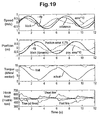
- a graph 140 shows rig heave and rig acceleration versus time
- another graph 141 shows the frequency spectrum of the acceleration signal in graph 140.
- the data was recorded on the drillship Deepwater Frontier on 10th October 2001 .
- the rig acceleration 142 and the rig heave 143 are the outputs PosMonD and AccMonD from an MRU-5, i.e. position and acceleration signals in the vertical axis respectively (positive acceleration upwards).
- the acceleration signal 142 has a frequency of about 0.1Hz and that noise is superimposed on the trace.
- noise in the acceleration signal is almost constant from about 1Hz up to 4.5Hz (which is the Nyquist frequency for these measurements). This indicates that the cut-off frequency in the MRU vibration filter is set too high.
- the low frequency noise ⁇ 0.03Hz
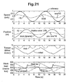
- a graph 160 shows how rig heave varies over a two minute period
- a graph 161 shows how heave velocity varies over the same time.
- the graphs 160 and 161 were generated using to MRU-5s (configured in the same way) and therefore each graph has two traces. It is clear from the two traces on each graph that the outputs from each MRU are not identical.
- a Simulink model was created to study the drawworks dynamics and the effects of the heave compensation corrections suggested above.
- the model has the following features:
- the compensation error is smallest at a wave period corresponding to the center frequency of the MRU filters (at approximately 10s) and it increases rapidly for shorter wave periods.
- the friction compensation has a large effect on the reduction of the position error from 4.7% to 1% in 10s period and 500 tons load.
- the effect of friction compensation increases proportionally with the load.
- Stiffening of the speed controller improves the compensation accuracy significantly, especially when speed corrections for MRU, drive and friction compensation are not applied.
- an apparatus for implementing a second embodiment of the method according to the invention is generally identified by reference numeral 200.
- the apparatus 200 is generally similar to the first embodiment except that the dead line and anchor 28 have been replaced by a drawworks similar to the drawworks 30.
- the apparatus therefore has two drawworks 201, 202 (known as 'dual drawworks), one on either side of the derrick (not shown in Fig. 25 ); although it is possible to stack the drawworks on top of one another on one side of the derrick.
- Each drawworks 201, 202 has its own power supply.
- Each end of the steel rope 226 (or drill line) is attached to a respective one of the drawworks and the intermediate cable passes through the crown block 218 and travelling block 220.
- travelling block 220 can be raised and lowered by reeling cable 228 on and off either one of the drawworks 201, 202, (so-called 'single mode') or both drawworks simultaneously (so-called 'dual mode').
- the dual mode can either be run at the same speed (synchronous mode), or run at different speeds (asynchronous mode).
- the drawworks 201, 202 are each run with the same speed and the centre sheave of the crown block 218 is non-rotating. Whilst the line speed magnitude increases towards the ends spooled in or out of the drum, the relatively low line speed in the synchronous mode has many advantages, such as 1) lower inertia of the line and sheave system, 2) higher acceleration limits for line slack and 3) less wear and bending induced fatigue load of the cable 226. There are also some advantages if the speed ratio of the drawworks is changed from the synchronous 50/50 ratio to 40/60 or 60/40 ratio, for example. This will distribute the line wear more evenly along line and thereby extend the line life as compared with a constant 50/50 ratio.
- the remaining unit should take into account the motion of the failed unit during the short but finite stopping time.
- This speed splitting software can be implemented in one single PLC (e.g. a drawworks controller like the drawworks controller 38) to control both drawworks 201, 202.
- PLC e.g. a drawworks controller like the drawworks controller 38
- the PLC sets or calculates the parameters and variables shown and holds them in memory.
- the speed factor s 1 is set by the operator between 0 and 1. Typically s 1 is set at 0.5 resulting in a 50/50 split of the speed command received from the limiting module 133.
- the optimal values for time delay t d , the position control parameter f p and the feed-back constant ⁇ p must be determined by trial and error during commissioning.
- the motion components, acceleration, speed and position for each unit are basically determined from motor encoders in the same way as they are for conventional single drawworks. However, instead of one transmission radius discussed earlier for a conventional single drawworks) there are now two radii, one for each drawworks. They differ from each other when the drums have different number of layers.
- step ES2 the controller checks to see if one or other of the drawworks is disabled (for whatever reason). If so, the algorithm jumps to step ES5. Otherwise at step ES3 the speed split is between the two drawworks 201, 202 using the speed factor s 1 .
- Step ES4 is intended to compensate for this error.
- the actual total block height is obtained from angular position encoders on each drawworks.
- the actual total block height h is obtained from the position values for each drawworks 201, 202.
- the height error h err is then determined by comparing the actual block height component h 1 with the proportion of the total block height h according to the speed factor s 1 .
- a corrective balancing speed v bal is calculated.
- Step ES5 is calculated only if one of the units is disabled, typically as a consequence of a failure. Disabling of a unit can occur abruptly when the unit is in full motion. In such cases operator set speed factor is overridden and the remaining unit provides all of the set speed. However, even when the disabled unit stops by means of its emergency brakes, it will not stop instantly. To make the transition from dual mode to single mode as smooth as possible, the transient, measured speed of the disabled drawworks is subtracted from the set speed of the remaining active unit. The time delay correction based on the acceleration of the disabled unit is added for minimising the compensation errors during the transition time interval. When the disabled unit has come to a complete stop, these terms automatically reduce to zero and have no effect.
- a control diagram 250 is generally similar to the control diagram 130 with like reference numerals indicating like parts.
- the adjusted heave compensation signal is passed to a splitter module 252.
- the splitter module 252 comprises computer executable instructions stored in the memory of the drawworks controller 38 and is functions to determine the set speed of each drawworks 201, 202 (including any position correction). Each set speed is sent to a respective drive 254, 256 of the drawworks 201, 202 which controls the speed accordingly.
- the output speeds of the two drawworks are summed to control the velocity of the travelling block 220.
- the motion of the drilling rig is superimposed on this output speed; assuming accurate heave compensation the final movement v global of the travelling block 220 will be substantially equal to the input by the operator v op .
- MRU Mobility Unit
- MRU speed corrections
- drive friction and/or delay
- functionality provided by the invention is for the functionality provided by the invention to be provided in a separate PLC (i.e. not part of a drawworks controller).
- the invention brings about particular benefits in the field of oil and gas extraction at sea (e.g. drilling operations, well service operations including coil tubing, wireline operations, etc.), the use of the invention is not limited to this field.
- Other fields of use are envisaged such as any hoisting equipment (e.g. cranes and winches) for use on vessels where the effects of heave need to be reduced, for example pipe and cable laying vessels.
- the embodiments of the invention described with reference to the drawings comprises computer apparatus and methods performed in computer apparatus, the invention also extends to computer programs, particularly computer programs on or in a carrier, adapted for putting the invention into practice.
- the program may be in the form of source code, object code, a code intermediate source and object code such as in partially compiled form, or in any other form suitable for use in the implementation of the methods according to the invention.
- the carrier may be any entity or device capable of carrying the program.
- the carrier may comprise a storage medium, such as a ROM, for example a CD ROM or a semiconductor ROM, or a magnetic recording medium, for example a floppy disc or hard disk.
- the carrier may be a transmissible carrier such as an electrical or optical signal that may be conveyed via electrical or optical cable or by radio or other means.
- the carrier may be constituted by such cable or other device or means.
- the carrier may be an integrated circuit in which the program is embedded, the integrated circuit being adapted for performing, or for use in the performance of, the relevant methods.
- Lever arm MRU X: 15.22 Y: 0.00 Z: 2191[m]
- Lever arm MP X: -11.73 Y: 0.00 Z: 1.20 [m]
- Heave Config Filter mode Hydrographic survey Filter parameters: Damping: 0.70 Periode: 25.00 [s]
- Emulate MRU type :
- BS1 Read, set or calculate input parameters/variables: a mru MRU acceleration v mru MRU velocity p mru MRU position ⁇ damping parameter of MRU filter ⁇ c angular cut-off frequency of MRU filter t i integration time constant of speed controller t m motor time constant of speed controller t d delay time ⁇ t time increment F ext external load (hook load) ⁇ dw drawworks efficiency d dw liner damping coefficient of drawworks V travelling block speed M total effective inertia mass BS2.
- MRU correction V G 2 ⁇ * ⁇ c *p mru drive correction BS3.
- v mru v mru + v G + v H + v F + V delay corrected heave compensation speed BS7.
- AHC_On flag for heave compensatio v mruCorr MRU velocity (after correction) p mru MRU position t fade fade time (typical 5 s) ⁇ t time increment CS2.
- DS1 Read, set or calculate input parameters/variables: a ramp acceleration limit from drive or operator F mMax motor pull force limit (at low speed) h actual block position h min minimum position (lower stop target) M total effective inertia mass M sl inertial mass of line and sheaves P min regenerative power limit P max motoring power limit ( ⁇ 0) v mMin motor based speed limit ( ⁇ 0) ⁇ v std standard speed increment ⁇ t time increment ⁇ clip factor for clipping error compensation DS2.
- Increment speed limit v min v old - ⁇ v minimum speed DS4.
- Motor push force limit F min min(-F mMax , P max /v lim ) minimum motor force
- F net F min - F ext net (downwards) push force DS10.
- Downwards acceleration limits a motors F net /M motor based acceleration limit ( ⁇ 0)
- a slack -F ext /M sl ) line slack acceleration limit
- a min max(a motors , -a ramp , a slack ) selectmost restricted acceleration ( ⁇ 0) DS11.
- v set set speed (desired block speed) s 1 speed factor for drawworks unit 1 h 1 block height from unit 1 h 2 block height from unit 2 v 1 block speed from unit 1 v 2 block speed from unit 2 a 1 block acceleration from unit 1 a 2 block acceleration from unit 2 t d time delay (signal & response delay)
- f p parameter for position control (0 ⁇ f p ⁇ 1) ⁇ bal position balancing constant ( ⁇ 0.1 s -1 ) unit 1 Disabled flag for failed/disabled unit 1 unit2Disabled flag for failed/disabled unit 1 ES2.
Landscapes
- Engineering & Computer Science (AREA)
- Life Sciences & Earth Sciences (AREA)
- Geology (AREA)
- Mining & Mineral Resources (AREA)
- Physics & Mathematics (AREA)
- Fluid Mechanics (AREA)
- Automation & Control Theory (AREA)
- Mechanical Engineering (AREA)
- Aviation & Aerospace Engineering (AREA)
- Radar, Positioning & Navigation (AREA)
- General Physics & Mathematics (AREA)
- Environmental & Geological Engineering (AREA)
- Remote Sensing (AREA)
- General Life Sciences & Earth Sciences (AREA)
- Geochemistry & Mineralogy (AREA)
- Earth Drilling (AREA)
- Medicines Containing Plant Substances (AREA)
- Steroid Compounds (AREA)
Claims (15)
- Verfahren zur aktiven Kompensation des Seegangs von einem Gefäß, an dem eine Last befestigt ist, wobei eine Verbindungsvorrichtung vorliegt, die die Last mit dem Gefäß verbindet, wobei das Verfahren die Schritte umfasst:(a) Messen des Seegangs von dem Gefäß mit einer Messvorrichtung und Ausgeben von einem Seegangssignal, das dafür repräsentativ ist, wobei das Seegangssignal ein Geschwindinkeitssignal umfasst das die Geschwindigkeit von dem Gefäß in Reaktion auf den Seegang repräsentiert;(b) Verwenden des Seegangssignals, um den Seegang zu kompensieren, indem die Verbindungsvorrichtung relativ zu dem Gefäß als eine Funktion des Seeganssignals bewegt wird, wodurch die Bewegung von der Last auf Grund des Seegangs verringert wird;wobei das Seegangsignal Fehler umfasst, die durch die Messvorrichtung induziert sind, wodurch die Genauigkeit von der Kompensation verringert wird, gekennzeichnet durch die folgenden Schritte:(c) Verarbeiten des Seegangssignals durch das Bestimmen von einer Geschwindigkeitskorrektur (vG ) und durch das Anpassen von dem Geschwindigkeitssignal mittels der Geschwindigkeitskorrektur, um so die Fehler zu verringern, und Ausgeben von einem angepassten Seegangssignai; und(d) Verwenden von dem angepassten Seegangssignal, um die Verbindungsvorrichtung zu bewegen, um den Seegang zu kompensieren.
- Verfahren nach Anspruch 1, wobei der Schritt (c) das Verringern von einem Leitungsphasenfehler [Engl.: Lead-Phase-Error] in dem Geschwindigkeitssignal durch das Hinzufügen der Geschwindigkeitskorrektur (vG ) zu dem Geschwindigkeitssignal umfasst, wobei die Geschwindigkeitskorrektur proportional zu einem Positionssignal ist, welches die Position von dem Gefäß in Bezug auf einen Festpunkt repräsentiert.
- Verfahren nach einem der vorhergehenden Ansprüche, wobei das Gefäß einen Antriebsapparat zum Bewirken von einer Bewegung von der Verbindungvorrichtung als eine Funktion von dem Seegangssignal umfasst, wobei das Verfahren ferner den Schritt des weiteren Anpassens von dem Seegangssignal umfasst, um Fehler zu verringern, die durch Trägheits- und/oder Reibungseffekte von dem Antriebsapparat beim Bewirken von der Bewegung von der Verbindungsvorrichtung eingeführt werden.
- Verfahren nach Anspruch 3, wobei das weitere Anpassen proportional zu (a) einer Antriebszeitkonstante, die der Quotient aus einem Trägheitsmoment (J) von dem Antriebapparat geteilt durch eine Verstärkung (P) von einem Proportional-Integral (PI) Geschwindigkeitsregler von einem elektronischen Reglersystem von einem Antrieb von dem Antriebapparat ist, und (b) einem Beschleunigungssignal ist, das einen gefilterten Wert für die Beschleunigung von dem Gefäß in Reaktion auf den Seegang repräsentiert, wodurch das Seegangsignal angepasst wird, um Trägheitsfehler, die durch den Antriebsapparat eingeführt werden, zu kompensieren.
- Verfahren nach Anspruch 4, wobei das weitere Anpassen proportional zu (a) einer Antriebszeitkonstante und (b) einem Beschleunigungssignal ist, das ein gefilterter Wert von der Reibungsbeschleunigung ist, die der Quotient aus einer Reibungskraft (Ff ), die von dem Antriebsapparat erfahren wird, geteilt durch eine Trägheitsgesamtmasse (M) von dem Antriebapparat ist, wodurch das Seegangsignal angepasst wird, um Trägheitsfehler, die durch den Antriebsapparat eingeführt werden, zu kompensieren.
- Verfahren nach einem der Ansprüche 4 oder 5, wobei das Beschleunigungssignal mit einem Beschleunigungsfilter gefiltert wurde, der einen Hochpass erster Ordnung umfasst, der eine Zeitkonstante hat, die im Wesentlichen gleich mit einer Integrationszeitkonstante (ti) von dem Proportional-Integral (PI) Geschwindigkeitsregler ist.
- Verfahren nach einem der vorhergehenden Ansprüche, ferner umfassend den Schritt des Anlegens von dynamischen Begrenzungen für das Ausmaß der Seegangskompensation, wobei die Begrenzungen als eine Funktion der Beschleunigungsleistungsfähigkeiten von einem Antriebsapparat oder der Verbindungvorrichtung erfasst sind.
- Verfahren nach Anspruch 7, ferner umfassend den Schritt des Bestimmens von einer maximalen und minimalen zulässigen Beschleunigung von der Verbindungsvorrichtung, welche die dynamischen Begrenzungen als eine obere Begrenzung und eine untere Begrenzung auf der Basis davon definiert, und das Begrenzen von der Bewegung der Verbindungsvorrichtung, basierend auf den oberen und unteren Begrenzungen.
- Verfahren nach Anspruch 7 oder 8, ferner umfassend den Schritt des Bestimmens von einer maximalen und einer minimalen Geschwindigkeitsbegrenzung aus der gegenwärtigen Position von der Verbindungsvorrichtung, sodass die Last innerhalb einer konstanten oder dynamischen Positionsbegrenzung angehalten werden kann.
- Verfahren nach Anspruch 7, 8 oder 9, wobei das Anlegen von dynamischen Begrenzungen ein asymmetrisches Abschneiden [Engl.: clipping] von dem angepassten Seegangssignal verursacht, wodurch sich eine mittlere Position von der Verbindungsvorrichtung mit der Zeit bewegt, wobei das Verfahren ferner den Schritt des Kompensierens von dem angepassten Seegangssignal für das asymmetrische Abschneiden umfasst, um die Bewegung der mittleren Position zu verringern.
- Verfahren nach Anspruch 10, wobei der Kompensationsschritt das Rückführen von dem angepassten Seegangssignal im Anschluss an das Abschneiden, das Bestimmen von einem Abschneidekompensationssianal und das Hinzufügen des Abschneidekompensationssignals zu dem angepassten Seegangssignal umfasst.
- Verfahren nach einem der vorhergehenden Ansprüche, wobei es zwei Hebewerke zum Steuern der Position von der Verbindungsvorrichtung gibt, wobei zwischen den zwei Hebewerke ein Kabel vorliegt, dass sich durch die Verbindungsvorrichtung erstreckt, wobei das Verfahren ferner die Schritte des Aufteilens von dem angepassten Seegangskompensationssignal zwischen den zwei Hebewerken umfasst, so dass jedes einen Teil davon anwendet, um die Position von der Verbindungsvorrichtung zu steuern.
- Verfahren nach Anspruch 12, ferner umfassend den Schritt des Aufteilens von dem angepassten Seegangskompensationssignal zwischen den zwei Hebewerken und zwar (a) im Wesentlichen gleich oder (b) ungleich.
- Verfahren nach Anspruch 12 oder 13, ferner umfassend den Schritt des Anweisens von einem von den zwei Hebewerken die gesamte Seegangskompensation bereitzustellen, wenn das andere von den zwei Hebewerken deaktiviert ist.
- Verfahren nach einem der vorhergehenden Ansprüche, wobei das Gesäß eine schwimmende Bohranlage ist, wobei die Verbindungsvorrichtung einen Laufblock umfasst, und Schritt (b) das Bewegen des Laufblocks mit Hebewerken umfasst, um den Seegang zu kompensieren.
Applications Claiming Priority (1)
| Application Number | Priority Date | Filing Date | Title |
|---|---|---|---|
| PCT/GB2006/050430 WO2008068445A1 (en) | 2006-12-06 | 2006-12-06 | Method and apparatus for active heave compensation |
Publications (2)
| Publication Number | Publication Date |
|---|---|
| EP2092402A1 EP2092402A1 (de) | 2009-08-26 |
| EP2092402B1 true EP2092402B1 (de) | 2015-08-05 |
Family
ID=37714495
Family Applications (1)
| Application Number | Title | Priority Date | Filing Date |
|---|---|---|---|
| EP06820656.4A Active EP2092402B1 (de) | 2006-12-06 | 2006-12-06 | Verfahren und vorrichtung für aktive seebewegungskompensation |
Country Status (7)
| Country | Link |
|---|---|
| US (1) | US8265811B2 (de) |
| EP (1) | EP2092402B1 (de) |
| BR (1) | BRPI0622075B1 (de) |
| CA (1) | CA2671339C (de) |
| DK (1) | DK2092402T3 (de) |
| NO (1) | NO337641B1 (de) |
| WO (1) | WO2008068445A1 (de) |
Families Citing this family (49)
| Publication number | Priority date | Publication date | Assignee | Title |
|---|---|---|---|---|
| WO2010101832A2 (en) * | 2009-03-02 | 2010-09-10 | General Electric Company | Drive assembly and apparatus for hoist |
| US8776711B2 (en) * | 2009-12-21 | 2014-07-15 | Eaton Corporation | Active heave compensation with active damping control |
| DE102010015359A1 (de) * | 2010-04-19 | 2011-10-20 | Howaldtswerke-Deutsche Werft Gmbh | Beurteilung der Schiffsdynamik |
| SE536059C2 (sv) * | 2010-07-29 | 2013-04-16 | C2Sat Comm Ab | Förfarande för att driftkompensera ett positionsmätningsorgan |
| KR101287329B1 (ko) * | 2011-06-14 | 2013-07-22 | 현대중공업 주식회사 | Bop 조립체의 수중 보관을 위한 슬롯을 갖는 시추시스템 |
| EP2726835A4 (de) * | 2011-06-28 | 2015-09-09 | Ibm | Schwingungsüberwachungssystem |
| US8510200B2 (en) | 2011-12-02 | 2013-08-13 | Spireon, Inc. | Geospatial data based assessment of driver behavior |
| US10169822B2 (en) | 2011-12-02 | 2019-01-01 | Spireon, Inc. | Insurance rate optimization through driver behavior monitoring |
| DE102012004802A1 (de) * | 2012-03-09 | 2013-09-12 | Liebherr-Werk Nenzing Gmbh | Kransteuerung mit Aufteilung einer kinematisch beschränkten Größe des Hubwerks |
| MY168361A (en) | 2012-06-01 | 2018-10-31 | Seatrax Inc | In the united states patent and trademark office |
| US20140095061A1 (en) * | 2012-10-03 | 2014-04-03 | Richard Franklin HYDE | Safety distance monitoring of adjacent vehicles |
| US9779379B2 (en) | 2012-11-05 | 2017-10-03 | Spireon, Inc. | Container verification through an electrical receptacle and plug associated with a container and a transport vehicle of an intermodal freight transport system |
| US8933802B2 (en) | 2012-11-05 | 2015-01-13 | Spireon, Inc. | Switch and actuator coupling in a chassis of a container associated with an intermodal freight transport system |
| US9688516B2 (en) | 2013-03-15 | 2017-06-27 | Oil States Industries, Inc. | Elastomeric load compensators for load compensation of cranes |
| DK178120B1 (en) | 2013-04-18 | 2015-06-01 | A P Møller Mærsk As | An Offshore Floating Vessel and a Method of Operating the Same |
| US9779449B2 (en) | 2013-08-30 | 2017-10-03 | Spireon, Inc. | Veracity determination through comparison of a geospatial location of a vehicle with a provided data |
| NO335595B1 (no) * | 2013-08-30 | 2015-01-12 | Kongsberg Maritime As | Effektstyring i sjøfartøyer |
| NO20131666A1 (no) | 2013-12-13 | 2015-06-15 | Tts Ships Equipment As | Fremgangsmåte og system for å detektere forekommende slakk heiseline i en vinsj |
| US20150186991A1 (en) | 2013-12-31 | 2015-07-02 | David M. Meyer | Creditor alert when a vehicle enters an impound lot |
| EP3550175A1 (de) | 2014-03-13 | 2019-10-09 | Oil States Industries, Inc | Lastkompensator mit in einem rohrförmigen gehäuse enthaltener spannfederanordnung |
| WO2015138833A1 (en) * | 2014-03-13 | 2015-09-17 | Canrig Drilling Technology Ltd. | Low inertia direct drive drawworks |
| JP6204873B2 (ja) * | 2014-04-21 | 2017-09-27 | 株式会社神戸製鋼所 | 電動ウインチ装置 |
| NO343555B1 (no) | 2014-12-02 | 2019-04-01 | Electrical Subsea & Drilling As | Anordning og fremgangsmåte ved aktiv hiv kompensering |
| US10378290B2 (en) * | 2014-12-23 | 2019-08-13 | National Oilwell Varco Norway As | System for hoisting a load on a drilling rig |
| US10207905B2 (en) | 2015-02-05 | 2019-02-19 | Schlumberger Technology Corporation | Control system for winch and capstan |
| CA2971423C (en) * | 2015-02-13 | 2019-08-13 | Halliburton Energy Services, Inc. | Real-time tracking and mitigating of bending fatigue in coiled tubing |
| MX2017010866A (es) * | 2015-02-23 | 2018-05-17 | Transocean Sedco Forex Ventures Ltd | Monitoreo y predicción del desempeño en tiempo real de un malacate con compensación del movimiento marino. |
| US9551788B2 (en) | 2015-03-24 | 2017-01-24 | Jim Epler | Fleet pan to provide measurement and location of a stored transport item while maximizing space in an interior cavity of a trailer |
| EP3124740B1 (de) * | 2015-07-27 | 2019-04-03 | BAUER Spezialtiefbau GmbH | Bohrgerät und verfahren zum erstellen einer bohrung von einer schwimmenden plattform |
| US10150541B2 (en) | 2016-01-15 | 2018-12-11 | Halliburton Energy Services, Inc. | Offshore drilling platform vibration compensation using an iterative learning method |
| BR112018016959B1 (pt) | 2016-02-22 | 2023-04-04 | Safelink As | Compensador de levantamento ativo móvel |
| JP7059605B2 (ja) * | 2017-12-08 | 2022-04-26 | 富士電機株式会社 | クレーンの運転制御装置 |
| CN109268003A (zh) * | 2018-09-14 | 2019-01-25 | 中国石化江汉油田分公司江汉采油厂 | 一种地质工程一体化框架下的致密油增产数学建模方法 |
| CN110032074B (zh) * | 2019-05-22 | 2022-04-19 | 中国科学院光电技术研究所 | 一种双路前馈扰动观测器的双补偿器设计方法 |
| CN110576941B (zh) * | 2019-09-25 | 2021-03-02 | 大连理工大学 | 一种具有电磁阻尼的被动式波浪补偿装置 |
| CN111807247A (zh) * | 2020-08-05 | 2020-10-23 | 中海石油(中国)有限公司 | 适用于双井架钻机的双绞车提升与主动补偿系统 |
| CN112611382B (zh) * | 2020-11-27 | 2022-06-21 | 哈尔滨工程大学 | 一种带有相位补偿的捷联惯导系统升沉测量方法 |
| CN112629540B (zh) * | 2020-12-16 | 2024-02-09 | 北京航天控制仪器研究所 | 一种基于载体姿态信息的升沉测量方法 |
| CN114123914B (zh) * | 2021-11-19 | 2023-11-14 | 美的威灵电机技术(上海)有限公司 | 电机的控制方法、控制装置、控制系统和可读存储介质 |
| CN114014179B (zh) * | 2021-11-22 | 2024-01-30 | 湖南科技大学 | 一种电驱动海洋绞车主动升沉补偿系统滑模控制方法 |
| NO347780B1 (en) * | 2021-12-03 | 2024-03-25 | Kongsberg Maritime As | Pull-in of dynamic cables for floating wind turbines |
| CN114499317A (zh) * | 2022-01-11 | 2022-05-13 | 浪潮云信息技术股份公司 | 应用于主动绞车升沉补偿的预测控制方法及系统 |
| JP7518125B2 (ja) * | 2022-04-21 | 2024-07-17 | ヤマハ発動機株式会社 | 船舶の速度制御方法及び船舶 |
| CN116295389B (zh) * | 2023-05-23 | 2023-08-04 | 中国船舶集团有限公司第七〇七研究所 | 一种捷联罗经系统状态平稳切换方法、装置、设备和介质 |
| CN119335893A (zh) * | 2024-08-30 | 2025-01-21 | 中山大学 | 用于主动升沉补偿系统的联合仿真方法、设备及介质 |
| CN118821494B (zh) * | 2024-09-18 | 2025-03-18 | 齐鲁工业大学(山东省科学院) | 海洋电导率传感器动态特性补偿方法 |
| CN119714343B (zh) * | 2024-12-20 | 2025-09-30 | 哈尔滨工程大学 | 一种基于互补滤波的升沉测量方法 |
| CN120871640B (zh) * | 2025-09-26 | 2025-11-28 | 中国船舶集团有限公司第七一九研究所 | 潜水用吊放操控方法、装置、存储介质及电子设备 |
| CN121071271B (zh) * | 2025-11-10 | 2026-02-27 | 武汉华中航空测控技术有限公司 | 船用起重机升沉补偿系统及升沉补偿方法、装置和设备 |
Family Cites Families (19)
| Publication number | Priority date | Publication date | Assignee | Title |
|---|---|---|---|---|
| US4104608A (en) * | 1977-03-30 | 1978-08-01 | The United States Of America As Represented By The Secretary Of The Navy | Heave meter |
| EP0261731B1 (de) | 1986-09-16 | 1994-03-16 | Eurosense Hoversounding N.V. | Verfahren und Gerät zur Messung der Tiefe unter einer Wasseroberfläche |
| GB2215468B (en) | 1988-03-02 | 1992-10-14 | Technical Survey Services Ltd | Apparatus and method for measuring the vertical displacement of a floating platform and a method of determining the pitch and roll thereof |
| US5130926A (en) * | 1989-02-08 | 1992-07-14 | Aisin Seiki Kabushiki Kaisha | Pressure control system for suspension |
| US5209302A (en) * | 1991-10-04 | 1993-05-11 | Retsco, Inc. | Semi-active heave compensation system for marine vessels |
| US5894895A (en) * | 1996-11-25 | 1999-04-20 | Welsh; Walter Thomas | Heave compensator for drill ships |
| US6216789B1 (en) * | 1999-07-19 | 2001-04-17 | Schlumberger Technology Corporation | Heave compensated wireline logging winch system and method of use |
| US6082947A (en) * | 1999-08-17 | 2000-07-04 | Adamson; James E. | Coordinated motion marine lifting device |
| US6201763B1 (en) * | 1999-09-20 | 2001-03-13 | The United States Of America As Represented By The Secretary Of The Navy | Depthimeter |
| US6382022B1 (en) * | 2000-03-27 | 2002-05-07 | The United States Of America As Represented By The Secretary Of The Navy | Shipboard wave measurement system |
| US6836707B2 (en) * | 2002-05-30 | 2004-12-28 | Honeywell International Inc. | Methods and systems for determining heave and heave rate of vessels |
| NO320692B1 (no) * | 2002-12-30 | 2006-01-16 | Stiftelsen Det Norske Veritas | Fremgangsmate og system for testing av datamaskinbaserte styre- og overvakningssystemer i et fartoy via en kommunikasjonskanal |
| US6926259B1 (en) * | 2003-03-12 | 2005-08-09 | Itrec B.V. | Hoist system |
| GB0316375D0 (en) | 2003-07-12 | 2003-08-13 | Stolt Offshore Sa | Method and associated apparatus for abandonment and recovery at sea |
| US7231981B2 (en) * | 2003-10-08 | 2007-06-19 | National Oilwell, L.P. | Inline compensator for a floating drill rig |
| US6935262B2 (en) * | 2004-01-28 | 2005-08-30 | Itrec B.V. | Method for lowering an object to an underwater installation site using an ROV |
| GB0406336D0 (en) * | 2004-03-19 | 2004-04-21 | Subsea 7 Uk | Apparatus and method |
| US7281585B2 (en) * | 2006-02-15 | 2007-10-16 | Schlumberger Technology Corp. | Offshore coiled tubing heave compensation control system |
| EP2054335B1 (de) * | 2006-08-15 | 2012-04-04 | Hydralift Amclyde, Inc. | Direkt wirkender einzelscheiben-aktiv/passiv-hubkompensator |
-
2006
- 2006-12-06 DK DK06820656.4T patent/DK2092402T3/en active
- 2006-12-06 EP EP06820656.4A patent/EP2092402B1/de active Active
- 2006-12-06 WO PCT/GB2006/050430 patent/WO2008068445A1/en not_active Ceased
- 2006-12-06 US US12/517,398 patent/US8265811B2/en active Active
- 2006-12-06 CA CA2671339A patent/CA2671339C/en active Active
- 2006-12-06 BR BRPI0622075-4A patent/BRPI0622075B1/pt active IP Right Grant
-
2009
- 2009-06-18 NO NO20092335A patent/NO337641B1/no unknown
Also Published As
| Publication number | Publication date |
|---|---|
| EP2092402A1 (de) | 2009-08-26 |
| BRPI0622075B1 (pt) | 2017-12-12 |
| CA2671339C (en) | 2014-02-18 |
| WO2008068445A1 (en) | 2008-06-12 |
| NO20092335L (no) | 2009-08-27 |
| US8265811B2 (en) | 2012-09-11 |
| US20100057279A1 (en) | 2010-03-04 |
| NO337641B1 (no) | 2016-05-23 |
| DK2092402T3 (en) | 2015-10-12 |
| CA2671339A1 (en) | 2008-06-12 |
| BRPI0622075A2 (pt) | 2014-05-20 |
Similar Documents
| Publication | Publication Date | Title |
|---|---|---|
| EP2092402B1 (de) | Verfahren und vorrichtung für aktive seebewegungskompensation | |
| US12546204B2 (en) | Drilling system control for reducing stick-slip by calculating and reducing energy of upgoing rotational waves in a drillstring | |
| US10458223B2 (en) | System and method for mitigating stick-slip | |
| CA2937875C (en) | Improved control of wellbore trajectories | |
| CA2453015C (en) | Drilling rig closed loop controls | |
| US6216789B1 (en) | Heave compensated wireline logging winch system and method of use | |
| EP3303204B1 (de) | Verfahren und vorrichtung zur adaptiven bewegungskompensation | |
| CA3004133C (en) | Using models and relationships to obtain more efficient drilling using automatic drilling apparatus | |
| US20180320501A1 (en) | Rotational oscillation control using weight | |
| US20030123957A1 (en) | Active deployment system and method | |
| Boyadjieff et al. | Design considerations and field performance of an advanced automatic driller | |
| NO20171016A1 (en) | Multi-Path Hoisting Systems | |
| KR101912594B1 (ko) | 온보드 부유 시추 설비와 온보드 부유 시추 설비의 작동 방법 | |
| KR102482340B1 (ko) | 시추 호이스팅 장치 및 이를 구비한 해양 구조물 | |
| WO2009134135A1 (en) | Hoisting device |
Legal Events
| Date | Code | Title | Description |
|---|---|---|---|
| PUAI | Public reference made under article 153(3) epc to a published international application that has entered the european phase |
Free format text: ORIGINAL CODE: 0009012 |
|
| 17P | Request for examination filed |
Effective date: 20090611 |
|
| AK | Designated contracting states |
Kind code of ref document: A1 Designated state(s): AT BE BG CH CY CZ DE DK EE ES FI FR GB GR HU IE IS IT LI LT LU LV MC NL PL PT RO SE SI SK TR |
|
| DAX | Request for extension of the european patent (deleted) | ||
| 17Q | First examination report despatched |
Effective date: 20120518 |
|
| REG | Reference to a national code |
Ref country code: DE Ref legal event code: R079 Ref document number: 602006046206 Country of ref document: DE Free format text: PREVIOUS MAIN CLASS: G05D0001020000 Ipc: E21B0019090000 |
|
| GRAP | Despatch of communication of intention to grant a patent |
Free format text: ORIGINAL CODE: EPIDOSNIGR1 |
|
| RIC1 | Information provided on ipc code assigned before grant |
Ipc: E21B 19/09 20060101AFI20150306BHEP Ipc: G05D 1/02 20060101ALI20150306BHEP |
|
| INTG | Intention to grant announced |
Effective date: 20150324 |
|
| GRAS | Grant fee paid |
Free format text: ORIGINAL CODE: EPIDOSNIGR3 |
|
| GRAA | (expected) grant |
Free format text: ORIGINAL CODE: 0009210 |
|
| AK | Designated contracting states |
Kind code of ref document: B1 Designated state(s): AT BE BG CH CY CZ DE DK EE ES FI FR GB GR HU IE IS IT LI LT LU LV MC NL PL PT RO SE SI SK TR |
|
| REG | Reference to a national code |
Ref country code: GB Ref legal event code: FG4D |
|
| REG | Reference to a national code |
Ref country code: CH Ref legal event code: EP |
|
| REG | Reference to a national code |
Ref country code: AT Ref legal event code: REF Ref document number: 740830 Country of ref document: AT Kind code of ref document: T Effective date: 20150815 |
|
| REG | Reference to a national code |
Ref country code: IE Ref legal event code: FG4D |
|
| REG | Reference to a national code |
Ref country code: DE Ref legal event code: R096 Ref document number: 602006046206 Country of ref document: DE |
|
| REG | Reference to a national code |
Ref country code: DK Ref legal event code: T3 Effective date: 20151005 |
|
| REG | Reference to a national code |
Ref country code: NL Ref legal event code: FP |
|
| REG | Reference to a national code |
Ref country code: AT Ref legal event code: MK05 Ref document number: 740830 Country of ref document: AT Kind code of ref document: T Effective date: 20150805 |
|
| REG | Reference to a national code |
Ref country code: LT Ref legal event code: MG4D |
|
| PG25 | Lapsed in a contracting state [announced via postgrant information from national office to epo] |
Ref country code: LV Free format text: LAPSE BECAUSE OF FAILURE TO SUBMIT A TRANSLATION OF THE DESCRIPTION OR TO PAY THE FEE WITHIN THE PRESCRIBED TIME-LIMIT Effective date: 20150805 Ref country code: LT Free format text: LAPSE BECAUSE OF FAILURE TO SUBMIT A TRANSLATION OF THE DESCRIPTION OR TO PAY THE FEE WITHIN THE PRESCRIBED TIME-LIMIT Effective date: 20150805 Ref country code: FI Free format text: LAPSE BECAUSE OF FAILURE TO SUBMIT A TRANSLATION OF THE DESCRIPTION OR TO PAY THE FEE WITHIN THE PRESCRIBED TIME-LIMIT Effective date: 20150805 Ref country code: GR Free format text: LAPSE BECAUSE OF FAILURE TO SUBMIT A TRANSLATION OF THE DESCRIPTION OR TO PAY THE FEE WITHIN THE PRESCRIBED TIME-LIMIT Effective date: 20151106 |
|
| PG25 | Lapsed in a contracting state [announced via postgrant information from national office to epo] |
Ref country code: AT Free format text: LAPSE BECAUSE OF FAILURE TO SUBMIT A TRANSLATION OF THE DESCRIPTION OR TO PAY THE FEE WITHIN THE PRESCRIBED TIME-LIMIT Effective date: 20150805 Ref country code: PL Free format text: LAPSE BECAUSE OF FAILURE TO SUBMIT A TRANSLATION OF THE DESCRIPTION OR TO PAY THE FEE WITHIN THE PRESCRIBED TIME-LIMIT Effective date: 20150805 Ref country code: ES Free format text: LAPSE BECAUSE OF FAILURE TO SUBMIT A TRANSLATION OF THE DESCRIPTION OR TO PAY THE FEE WITHIN THE PRESCRIBED TIME-LIMIT Effective date: 20150805 Ref country code: IS Free format text: LAPSE BECAUSE OF FAILURE TO SUBMIT A TRANSLATION OF THE DESCRIPTION OR TO PAY THE FEE WITHIN THE PRESCRIBED TIME-LIMIT Effective date: 20151205 Ref country code: PT Free format text: LAPSE BECAUSE OF FAILURE TO SUBMIT A TRANSLATION OF THE DESCRIPTION OR TO PAY THE FEE WITHIN THE PRESCRIBED TIME-LIMIT Effective date: 20151207 Ref country code: SE Free format text: LAPSE BECAUSE OF FAILURE TO SUBMIT A TRANSLATION OF THE DESCRIPTION OR TO PAY THE FEE WITHIN THE PRESCRIBED TIME-LIMIT Effective date: 20150805 |
|
| PG25 | Lapsed in a contracting state [announced via postgrant information from national office to epo] |
Ref country code: SK Free format text: LAPSE BECAUSE OF FAILURE TO SUBMIT A TRANSLATION OF THE DESCRIPTION OR TO PAY THE FEE WITHIN THE PRESCRIBED TIME-LIMIT Effective date: 20150805 Ref country code: IT Free format text: LAPSE BECAUSE OF FAILURE TO SUBMIT A TRANSLATION OF THE DESCRIPTION OR TO PAY THE FEE WITHIN THE PRESCRIBED TIME-LIMIT Effective date: 20150805 Ref country code: CZ Free format text: LAPSE BECAUSE OF FAILURE TO SUBMIT A TRANSLATION OF THE DESCRIPTION OR TO PAY THE FEE WITHIN THE PRESCRIBED TIME-LIMIT Effective date: 20150805 Ref country code: EE Free format text: LAPSE BECAUSE OF FAILURE TO SUBMIT A TRANSLATION OF THE DESCRIPTION OR TO PAY THE FEE WITHIN THE PRESCRIBED TIME-LIMIT Effective date: 20150805 |
|
| REG | Reference to a national code |
Ref country code: DE Ref legal event code: R097 Ref document number: 602006046206 Country of ref document: DE |
|
| PG25 | Lapsed in a contracting state [announced via postgrant information from national office to epo] |
Ref country code: RO Free format text: LAPSE BECAUSE OF FAILURE TO SUBMIT A TRANSLATION OF THE DESCRIPTION OR TO PAY THE FEE WITHIN THE PRESCRIBED TIME-LIMIT Effective date: 20150805 Ref country code: BE Free format text: LAPSE BECAUSE OF NON-PAYMENT OF DUE FEES Effective date: 20151231 |
|
| PLBE | No opposition filed within time limit |
Free format text: ORIGINAL CODE: 0009261 |
|
| STAA | Information on the status of an ep patent application or granted ep patent |
Free format text: STATUS: NO OPPOSITION FILED WITHIN TIME LIMIT |
|
| REG | Reference to a national code |
Ref country code: DE Ref legal event code: R119 Ref document number: 602006046206 Country of ref document: DE |
|
| 26N | No opposition filed |
Effective date: 20160509 |
|
| PG25 | Lapsed in a contracting state [announced via postgrant information from national office to epo] |
Ref country code: MC Free format text: LAPSE BECAUSE OF FAILURE TO SUBMIT A TRANSLATION OF THE DESCRIPTION OR TO PAY THE FEE WITHIN THE PRESCRIBED TIME-LIMIT Effective date: 20150805 Ref country code: LU Free format text: LAPSE BECAUSE OF FAILURE TO SUBMIT A TRANSLATION OF THE DESCRIPTION OR TO PAY THE FEE WITHIN THE PRESCRIBED TIME-LIMIT Effective date: 20151206 |
|
| REG | Reference to a national code |
Ref country code: CH Ref legal event code: PL |
|
| PG25 | Lapsed in a contracting state [announced via postgrant information from national office to epo] |
Ref country code: SI Free format text: LAPSE BECAUSE OF FAILURE TO SUBMIT A TRANSLATION OF THE DESCRIPTION OR TO PAY THE FEE WITHIN THE PRESCRIBED TIME-LIMIT Effective date: 20150805 |
|
| REG | Reference to a national code |
Ref country code: IE Ref legal event code: MM4A |
|
| REG | Reference to a national code |
Ref country code: FR Ref legal event code: ST Effective date: 20160831 |
|
| PG25 | Lapsed in a contracting state [announced via postgrant information from national office to epo] |
Ref country code: DE Free format text: LAPSE BECAUSE OF NON-PAYMENT OF DUE FEES Effective date: 20160701 Ref country code: IE Free format text: LAPSE BECAUSE OF NON-PAYMENT OF DUE FEES Effective date: 20151206 Ref country code: LI Free format text: LAPSE BECAUSE OF NON-PAYMENT OF DUE FEES Effective date: 20151231 Ref country code: CH Free format text: LAPSE BECAUSE OF NON-PAYMENT OF DUE FEES Effective date: 20151231 |
|
| PG25 | Lapsed in a contracting state [announced via postgrant information from national office to epo] |
Ref country code: FR Free format text: LAPSE BECAUSE OF NON-PAYMENT OF DUE FEES Effective date: 20151231 |
|
| PG25 | Lapsed in a contracting state [announced via postgrant information from national office to epo] |
Ref country code: BE Free format text: LAPSE BECAUSE OF FAILURE TO SUBMIT A TRANSLATION OF THE DESCRIPTION OR TO PAY THE FEE WITHIN THE PRESCRIBED TIME-LIMIT Effective date: 20150805 |
|
| PG25 | Lapsed in a contracting state [announced via postgrant information from national office to epo] |
Ref country code: BG Free format text: LAPSE BECAUSE OF FAILURE TO SUBMIT A TRANSLATION OF THE DESCRIPTION OR TO PAY THE FEE WITHIN THE PRESCRIBED TIME-LIMIT Effective date: 20150805 Ref country code: HU Free format text: LAPSE BECAUSE OF FAILURE TO SUBMIT A TRANSLATION OF THE DESCRIPTION OR TO PAY THE FEE WITHIN THE PRESCRIBED TIME-LIMIT; INVALID AB INITIO Effective date: 20061206 |
|
| PG25 | Lapsed in a contracting state [announced via postgrant information from national office to epo] |
Ref country code: CY Free format text: LAPSE BECAUSE OF FAILURE TO SUBMIT A TRANSLATION OF THE DESCRIPTION OR TO PAY THE FEE WITHIN THE PRESCRIBED TIME-LIMIT Effective date: 20150805 |
|
| PG25 | Lapsed in a contracting state [announced via postgrant information from national office to epo] |
Ref country code: TR Free format text: LAPSE BECAUSE OF FAILURE TO SUBMIT A TRANSLATION OF THE DESCRIPTION OR TO PAY THE FEE WITHIN THE PRESCRIBED TIME-LIMIT Effective date: 20150805 |
|
| PGFP | Annual fee paid to national office [announced via postgrant information from national office to epo] |
Ref country code: NL Payment date: 20251003 Year of fee payment: 20 |
|
| PGFP | Annual fee paid to national office [announced via postgrant information from national office to epo] |
Ref country code: GB Payment date: 20251001 Year of fee payment: 20 |
|
| PGFP | Annual fee paid to national office [announced via postgrant information from national office to epo] |
Ref country code: DK Payment date: 20251212 Year of fee payment: 20 |