EP2092412B1 - Utilisation d'images en navigation alternative - Google Patents
Utilisation d'images en navigation alternative Download PDFInfo
- Publication number
- EP2092412B1 EP2092412B1 EP07869071.6A EP07869071A EP2092412B1 EP 2092412 B1 EP2092412 B1 EP 2092412B1 EP 07869071 A EP07869071 A EP 07869071A EP 2092412 B1 EP2092412 B1 EP 2092412B1
- Authority
- EP
- European Patent Office
- Prior art keywords
- icons
- controls
- computer program
- responsively
- network
- Prior art date
- Legal status (The legal status is an assumption and is not a legal conclusion. Google has not performed a legal analysis and makes no representation as to the accuracy of the status listed.)
- Not-in-force
Links
Images



Classifications
-
- G—PHYSICS
- G06—COMPUTING OR CALCULATING; COUNTING
- G06F—ELECTRIC DIGITAL DATA PROCESSING
- G06F3/00—Input arrangements for transferring data to be processed into a form capable of being handled by the computer; Output arrangements for transferring data from processing unit to output unit, e.g. interface arrangements
- G06F3/01—Input arrangements or combined input and output arrangements for interaction between user and computer
- G06F3/048—Interaction techniques based on graphical user interfaces [GUI]
- G06F3/0481—Interaction techniques based on graphical user interfaces [GUI] based on specific properties of the displayed interaction object or a metaphor-based environment, e.g. interaction with desktop elements like windows or icons, or assisted by a cursor's changing behaviour or appearance
- G06F3/0482—Interaction with lists of selectable items, e.g. menus
-
- G—PHYSICS
- G06—COMPUTING OR CALCULATING; COUNTING
- G06F—ELECTRIC DIGITAL DATA PROCESSING
- G06F3/00—Input arrangements for transferring data to be processed into a form capable of being handled by the computer; Output arrangements for transferring data from processing unit to output unit, e.g. interface arrangements
- G06F3/01—Input arrangements or combined input and output arrangements for interaction between user and computer
- G06F3/048—Interaction techniques based on graphical user interfaces [GUI]
- G06F3/0481—Interaction techniques based on graphical user interfaces [GUI] based on specific properties of the displayed interaction object or a metaphor-based environment, e.g. interaction with desktop elements like windows or icons, or assisted by a cursor's changing behaviour or appearance
- G06F3/04817—Interaction techniques based on graphical user interfaces [GUI] based on specific properties of the displayed interaction object or a metaphor-based environment, e.g. interaction with desktop elements like windows or icons, or assisted by a cursor's changing behaviour or appearance using icons
-
- H—ELECTRICITY
- H04—ELECTRIC COMMUNICATION TECHNIQUE
- H04L—TRANSMISSION OF DIGITAL INFORMATION, e.g. TELEGRAPHIC COMMUNICATION
- H04L41/00—Arrangements for maintenance, administration or management of data switching networks, e.g. of packet switching networks
- H04L41/22—Arrangements for maintenance, administration or management of data switching networks, e.g. of packet switching networks comprising specially adapted graphical user interfaces [GUI]
Definitions
- This invention relates to management of computer networks. More particularly, this invention relates to a graphical user interface for visualizing and controlling a computer network.
- GUI graphical user interface
- a graphical user interface is a computer terminal or monitor interface, based on graphics instead of text.
- a graphical representation appears on a display and a user can interact with the system using a selection device, for example a mouse.
- the management of a large computer system or network requires management of a large amount of data, which is typically organized hierarchically.
- a graphical user interface for visualizing and controlling a hierarchic structure may consist of a first icon or set of icons that represents the structure at the top level. If a user activates the first icon with the selection device, e.g., by clicking on it, a second set of icons appears, representing a lower level of the structure. This may be repeated until the user sees an icon representing the component or function to be managed.
- the well-known Windows Explorer utility of Microsoft ® Windows ® is an example of such a graphical user interface
- the graphical user interface may consist of menus and submenus representing the different devices and properties at different levels of the hierarchic structure. If a user activates the top-level menu, e.g., by clicking on it, a second level menu appears representing a lower level of the hierarchy. This may be repeated until the user sees a menu item representing the component or function to be managed.
- Child nodes at lower hierarchical levels that were not visible before selection are then made visible up to a predetermined number of levels within the hierarchy.
- a map is provided on the interface, which allows a user to graphically comprehend the present location of all nodes displayed on the interface in relation to their position within the overall hierarchy.
- the interface allows errors in low level devices within a network to be visually propagated up to the upper levels of the hierarchy, for display to a user viewing only the top levels.
- US 6144962 discloses a visual web site analysis program providing features for facilitating the analysis and management of web sites and web site content.
- a mapping component scans a web site and builds a site map which graphically depicts the URLs and links of the site to allow the user to visualize the overall architecture of the Web site.
- the system includes map navigation and URL filtering features.
- US 2005/091609 discloses a graphical user interface having a first area with an array of menu items.
- an icon such as a contextually-related animated icon is displayed on a second area and changes its appearance in such a way as to indicate to the user the location of the pointer and/or the consequence of selecting that menu item.
- US 2006/026509 discloses a system for representing network information by displaying one or more graphical components representing network entities in a first portion of a graphical user interface.
- An embedded browser is provided in a second portion of the graphical user interface.
- browser-compatible data is retrieved from a network entity corresponding to the selected graphical component, and the browser-compatible data is rendered in the embedded browser.
- US 2006/242604 discloses a method of creating and customizing multiple roots in a navigation pane. By selecting desired pages and adding them to the navigation pane, users may create multiple roots with which to navigate, to enable the user to bypass irrelevant pages while reducing the amount of information presented in the navigation pane.
- Software programming code which embodies aspects of the present invention, is typically maintained in permanent storage, such as a computer readable medium.
- such software programming code may be stored on a client or a server.
- the software programming code may be embodied on any of a variety of known media for use with a data processing system, such as a diskette, or hard drive, or CD-ROM.
- the code may be distributed on such media, or may be distributed to users from the memory or storage of one computer system over a network of some type to other computer systems for use by users of such other systems.
- the techniques and methods for embodying software program code on physical media and distributing software code via networks are well-known and will not be further discussed herein.
- GUI navigation techniques that are complementary to conventional menu techniques, e.g., dropdown menus, trees, drawers.
- computer networks typically comprise a combination of computer systems interconnected with a number of network communications devices such as modems, hubs, routers, bridges, and switches.
- network communications devices such as modems, hubs, routers, bridges, and switches.
- Such networks may be interconnected with other networks, such as those from government agencies, or other entities, to form a worldwide system of interconnected networks, such as the Internet.
- Such a computer network can be broken down logically into various hierarchical levels. For instance, a high speed fiberoptic link controlled by high speed routers might form a first level in a hierarchy.
- This top-level network may interconnect many smaller regional networks associated with specific buildings, cities, or geographical areas, each of which represents a second level in the network hierarchy. Each regional network may interconnect departmental networks representing a third level in the network hierarchy.
- Each departmental network may include many individual subnetworks of computers, terminals, printers, file and web servers, and so forth to form a fourth level of the hierarchy.
- Each computer and data communications device may then be considered on an individual basis as a fifth level in the hierarchy and may include various internal devices or peripherals, which form a sixth hierarchical level.
- Modern graphical user interfaces typically have one or more navigation panels and content areas.
- a content area is an area of a displayed page or screen, in which the user enters data, reads information.
- Navigation panels are realized, for example by menu bars, tool bars, or controls, which when actuated, cause some operation to be executed, or cause the content in the content area to be changed.
- a graphical representation of a hierarchical network management system is displayed in the content area of a page.
- This representation may describe the topological arrangement of the network.
- the representation may be a functional representation of the system, indicating processes, or data flows of the system (such as packet processing).
- the representation could be oriented toward security features, indicating privileges at various levels of the hierarchy.
- Many other representations of the network will occur to those skilled in the network management art. Indeed, the graphical representation could describe many systems and data collections unrelated to network management.
- a portion of the graphical representation is mapped to items in a simultaneously displayed menu.
- This mapping may be used to obtain help about the menu items. Additionally or alternatively, the mapping may serve as a convenient entry to a navigation path through the hierarchy via the menu.
- Context-sensitive help relating to elements of the graphical representation may be immediately available, responsively to a selection device. For example, in one embodiment, when a mouse pointer passes across an element of the graphical representation that is mapped to a menu item, a visual indicator, e.g., a tooltip, appears on the display, containing a short description about the item. Meanwhile, the menu item is highlighted on the appropriate menu, thereby facilitating an appropriate selection by the user.
- a visual indicator e.g., a tooltip
- a corresponding menu item is coordinately opened automatically in the menu bar, showing its submenu (if such exists), or executing a designated operation. Additionally or alternatively, selection of an item in the graphical representation may enable a more detailed help display, e.g., a popup window.
- the initial graphical representation of the system in the content area is a broad overview, mapped to a high level menu in the navigation panel.
- a submenu is exposed, and the initial graphical representation in the content area is replaced by a more detailed graphical map that represents the items in the submenu.
- This process may iterate, focusing on progressively narrower, but more detailed graphical representations of submenus, eventually reaching the level of the leaves of the hierarchical tree, at which point the process ends, or reiterates at a higher level.
- Ancillary help displays in the content area or elsewhere may be presented at various stages during the user interaction.
- the graphical representation may be tailored as a filter, so as to provide rapid access to a frequently accessed subset of options and entries that may be offered by the object. The user thereby avoids navigating through less frequently accessed items.
- the graphical representation complements the menus and submenus, which may be far more detailed in the case of a complex object.
- An embodiment of the invention provides enhancements in an authentication, authorization, and accounting (AAA) server used in the operation of a computer network in which a processing unit is linked to a memory, the network, a terminal, and a selection device.
- the processing unit executes a computer program causing the terminal to display a hierarchical model of the computer network, in which first and second icons representing network data items are arranged in respective first and second hierarchical levels.
- a navigation panel is also displayed, which has first and second controls respectively mapped to the first and second icons. When a pointer is moved to one of the first icons, a corresponding first control of the navigation panel is emphasized. Selection of one of the first icons causes them to be replaced by the second icons, and the navigation panel is simultaneously modified to display the second controls.
- the process may be iterated to view any number of hierarchical levels.
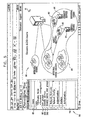
- Fig. 1 schematically depicts a simplified version of a networked data communication system 10, in which the techniques of the present invention may be implemented.
- the system 10 is a useful example for explaining the principles of the invention.
- the principles of the invention can be practiced with many different network systems and data hierarchies. Indeed, the principles of the invention can be applied using a standalone computer.
- a wireless network is shown in Fig. 1 by way of example and not of limitation.
- wireless links may be replaced in whole or in part by other known connections, in which case wireless network elements are replaced by other network elements.
- optical network devices such as add-drop multiplexers, regenerators, digital cross-connects, and section terminating equipment may be substituted for wireless uplink and downlink channels.
- the system 10 includes a head end 12 (also known as a central termination unit).
- the head end 12 includes an AAA server 14, which communicates with a plurality of nodes 16, and coordinates access between each of the nodes 16 and the head end 12.
- the head end 12 communicates with network devices in a network environment, gathering information on network elements through the use of a network management protocol that remotely queries the network devices and, in turn, the network devices provide status information.
- the AAA server 14 may include a memory 18 and at least one processor 20.
- a supervisory operator interacts with the AAA server 14 using a display 22, which may be realized as any suitably linked computer device or workstation having a suitable input device such as a keyboard 24, and a graphical selection device, such as a mouse 26. While a direct connection is shown between the AAA server 14 and the display 22, the AAA server 14 may communicate with other network elements using downlink channels 28 and uplink channels 30.
- wireless links comprising one or more downlink channels 28 and one or more uplink channels 30 between the head end 12 and the nodes 16 via any one of a plurality of wireless transmitting and receiving devices 32, shown as a satellite base station 34, an orbital satellite 36, and a radio tower 38.
- the nodes 16 may include any one of a number of wireless transmitting and receiving devices.
- a satellite dish 40 may be used to communicate with the head end 12 via the downlink channels 28 and the uplink channels 30.
- the satellite dish 40 may, in turn, be connected to a local area network 42 (LAN), which, may be further connected to one or more computer systems 44.
- Another wireless device may be a portable wireless computer system 46, which is able to transmit and receive information to the head end 12 via the downlink channels 28 and the uplink channels 30.
- Other devices 48 may include, for example, wireless telephones, handheld computing devices, etc.
- the downlink channels 28 and the uplink channels 30 may be utilized in a manner similar to that of the upstream and downstream channels of a cable modem network.
- Cable modem termination system domain assignment and Map Routing Techniques may easily be implemented in the system 10, as taught, for example, by commonly assigned U.S. Patent No. 7,085,287 .
- the techniques of the present invention may be easily implemented in any computer network, which uses shared access channels for communicating between a centralized computing system and one or more remote nodes.
- Fig. 2 is a flow chart illustrating a method of operation of a graphical user interface in accordance with a disclosed embodiment of the invention.
- the operations described below can be performed on pages of a document written in a markup language, e.g., HTML, and presented on the display 22 ( Fig. 1 ) using a conventional browser.
- the operations can be implemented by incorporating suitable HTML directives and instructions within the document.
- the method is performed iteratively, and for convenience is explained with reference to screen displays, which usually show a first iteration of respective steps. It will be understood that whenever desired, the user may cancel a currently represented level of the system hierarchy, e.g., by pressing the "Esc" key of a keyboard.
- Fig. 2 is explained with respect to a network management application, this is exemplary, and the method can be performed with many other applications employing a GUI.
- a user logs into an access control system management application.
- the application is suitable for controlling the network using the AAA server 14 ( Fig. 1 ).
- step 52 the user is presented with a graphical representation of the current level of the system hierarchy. In the first iteration, this is a top-level view. A menu bar or navigation panel is also presented.
- the user points or moves a graphical selection device, e.g., a mouse, over an area of the image.
- a graphical selection device e.g., a mouse
- the mouse pointer or the indicator of another conventional selection device
- the corresponding mapped element of the menu bar is automatically emphasized, e.g., by highlighting.
- a tooltip may also appear near the icon.
- the area indicated at step 54 is confirmed by actuating the selection device, e.g., by clicking a mouse, on an icon of the graphical representation, pressing an appropriate key of a keyboard, or making a selection from the currently emphasized menu.
- the user may choose to disregard the currently indicated area, and simply move the selection device to another area. This possibility is indicated by the broken line 59 leading from step 56.
- the selection could be confirmed simply by leaving the mouse in place for a predetermined time period.
- an escape sequence can be initiated at this time, e.g., by pressing the "Esc" key on the keyboard.
- step 58 If the determination at decision step 58 is negative, then it is concluded that the selected item was a terminal element in the hierarchy represented by the menu system and the graphical display. No further navigation of the menu system or graphical display occurs, because the selection corresponds to a definitive action to be taken, e.g., a command, program to be executed, or content to be displayed. Control proceeds to step 60 and the selection is executed. In the content area of the screen display, appropriate information representing the selected activity or function may now appear and optionally replaces the graphical representation. The procedure then terminates at final step 64.
- step 58 If the determination at decision step 58 is affirmative, then control proceeds to step 66.
- An appropriate element of the menu expands to show a submenu, and a new graphical representation showing a higher level of detail of the previously selected item appears. This higher level of detail corresponds to the submenu.
- Control returns to step 54 to begin another iteration. While not shown explicitly in Fig. 2 , it will be understood that the user may return to a higher level of the system hierarchy at any time, for example, by use of the browser's "back" control. Additionally or alternatively, return to a higher level may be effected by clicking a higher entry bar of the menu, or by clicking an icon indicating a return to a higher hierarchical level in the graphical representation.
- This example describes a series of screen displays that were developed by performing the method disclosed above with respect to Fig. 2 on a prototype embodiment.
- the computer application that was executed is a network access control management application, which is adapted to management of systems such as the system 10 ( Fig. 1 ).
- Fig. 3 is a screen display 68 including in its content area a typical graphical representation 70 of a network whose access is being managed, in accordance with a disclosed embodiment of the invention.
- the graphical representation 70 corresponds to step 52
- FIG. 2 a high level view orients the user to different system functions and their interrelations, and indicates possibilities for configuring the system using the access control system management application.
- a high level view orients the user to different system functions and their interrelations, and indicates possibilities for configuring the system using the access control system management application.
- the functional elements represented in Fig. 3 are an authentication function icon 72, an authorization function icon 74 and a users icon 76.
- a navigation panel 78 at the left of the screen display 68 has entries corresponding to elements of the graphical representation 70, for example an entry 80 labeled "users", which corresponds to the users icon 76.
- a mouse pointer 81 is present in an insignificant position within the content area of the screen display 68.
- Fig. 4 shows another state of the screen display 68 ( Fig. 3 ), in accordance with a disclosed embodiment of the invention.
- the pointer 81 was positioned generally over the users icon 76, thereby indicating the user function as a potential item of interest.
- a context-sensitive help description 82 was superimposed on the graphical representation 70, generally in the area occupied by the users icon 76.
- the entry 80 in the navigation panel was highlighted.
- the entry 80 is the menu drawer responsible for user configuration.
- the screen display 68 corresponding to step 54 ( Fig.
- the entry 80 could have been selected with the selection device or with another conventional input device, such as a keyboard or touch screen, as attention was drawn by its emphasis on the screen. The same result is produced in either case.
- FIG. 5 shows a screen display 84, which includes a graphical representation 86 of user configuration domains, and which is a more detailed version of the user functions represented by the users icon 76 ( Fig. 4 ) in accordance with a disclosed embodiment of the invention.
- This view corresponds to step 66 ( Fig. 2 ).
- the graphical representation 86 includes an internal users groups icon 88, group mapping icons 90, 92, and identity server icons 94, 96.
- the entry 80 in the navigation panel 78 is now expanded to show a submenu.
- An entry 98, labeled "User groups” corresponds to the internal users groups icon 88
- an entry 100, labeled “Identity servers” corresponds to the identity server icons 94, 96
- an entry 102, labeled "Identity server user groups mapping” corresponds to the group mapping icons 90, 92.
- the pointer 81 is again in an insignificant location in the content area of the screen display 84
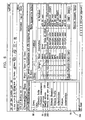
- Fig. 6 shows another screen display 104 that was produced in accordance with a disclosed embodiment of the invention.
- This view corresponds to step 60 ( Fig. 2 ).
- the appearance of the navigation panel 78 remains unchanged when compared to Fig. 5 .
- the graphical representation 86 ( Fig. 5 ) is no longer present.
- the content area comprises a list of ten users, from which a user 106 (Alex) has been selected. From this point operations respecting the user 106 were conducted conventionally.
- Fig. 7 is a screen display 108 showing a graphical representation 110 of a network being managed, in accordance with an alternate embodiment of the invention.
- the graphical representation 110 displays the same information as the graphical representation 70 ( Fig. 3 ), except that it occupies the content area of a popup window 112.
- the main display has a content area 114, which contains other content that may be of interest to the user.
- This embodiment has the advantage of displaying both a representation of a hierarchical system and content simultaneously.
- help information may be also shown, e.g., as tool tips or additional popup windows.
- Embodiment 3 is a screen display 108 showing a graphical representation 110 of a network being managed, in accordance with an alternate embodiment of the invention.
- the graphical representation 110 displays the same information as the graphical representation 70 ( Fig. 3 ), except that it occupies the content area of a popup window 112.
- the main display has a content area 114, which contains other content that may be of interest to the
- Such shortcuts are implemented as shortcut icons embedded in the graphical representation, preferably in the region of the graphical representation that relates to the desired operations.
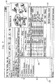
- Fig. 8 is a screen display 116 similar to the screen display 84 ( Fig. 5 ) in which some of the group icons have been augmented by shortcut icons in accordance with a disclosed embodiment of the invention.
- the internal users groups icon 88 now includes a shortcut icon 118.
- An internal users icon 120 includes a shortcut icon 122.
- a shortcut icon 124 directed to external users is now present.
- Applying a selection device, for example, to the internal users groups icon 88 has the same effect as described above with reference to Fig. 2 . However, applying the selection device to one of the shortcut icons 118, 122, 124 causes the target of the shortcut to be selected. This is the same result as is obtained by selecting a menu item in the navigation panel 78.
Landscapes
- Engineering & Computer Science (AREA)
- General Engineering & Computer Science (AREA)
- Theoretical Computer Science (AREA)
- Human Computer Interaction (AREA)
- Physics & Mathematics (AREA)
- General Physics & Mathematics (AREA)
- Computer Networks & Wireless Communication (AREA)
- Signal Processing (AREA)
- User Interface Of Digital Computer (AREA)
- Two-Way Televisions, Distribution Of Moving Picture Or The Like (AREA)
Claims (13)
- Système pour accéder à des informations hiérarchisées comprenant :une mémoire ; etune unité de traitement pouvant être connectée à une unité d'affichage, et à un dispositif de sélection comportant un indicateur visuel (81), ladite unité de traitement exécutant un programme informatique stocké dans ladite mémoire, dans lequel, en réponse à des instructions dudit programme informatique, ladite unité de traitement est configurée pour commander à ladite unité d'affichage de présenter visuellement un modèle hiérarchique (70) desdites informations, et un panneau de navigation (78) comportant des premières et secondes commandes (80,98), ledit modèle hiérarchique comprenant des première et deuxième icônes (76,88) disposées dans des premier et second niveaux hiérarchiques respectifs, et respectivement mappées sur lesdites première et seconde commandes ;dans lequel l'unité de traitement, en réponse à la présence dudit indicateur visuel à proximité de l'une quelconque desdites premières icônes, est configurée pour mettre en valeur une première commande correspondante dudit panneau de navigation, et
dans lequel l'unité de traitement, en réponse à la sélection de l'une quelconques desdites premières icônes, est configurée en outre pour remplacer lesdites premières icônes par lesdites secondes icônes, et pour modifier ledit panneau de navigation pour que celui-ci présente lesdites secondes commandes sur l'unité d'affichage. - Système selon la revendication 1, dans lequel les secondes commandes comprennent des sous-menus desdites premières commandes, l'unité de traitement est configurée, en réponse à la présentation desdites secondes commandes sur ledit panneau de navigation, pour remplacer lesdites premières icônes par lesdites secondes icônes.
- Système selon la revendication 1, dans lequel l'unité de traitement, en réponse à la présence dudit indicateur visuel à proximité de l'une quelconque desdites premières icônes, est configurée pour commander à ladite unité d'affichage de présenter un écran d'aide se rapportant à ladite première icône.
- Système selon la revendication 1, configuré pour présenter lesdites premières icônes dans une zone de contenu d'un écran sur ladite unité d'affichage.
- Système selon la revendication 1, configuré pour présenter lesdites premières icônes dans une fenêtre contextuelle sur ladite unité d'affichage.
- Système selon la revendication 1, dans lequel lesdites premières icônes comprennent des icônes de raccourci pour sélectionner un élément de données.
- Programme informatique comprenant un support lisible par ordinateur stockant un code de logiciel adapté, lorsqu'il est exécuté par un ordinateur, pour mettre en oeuvre un procédé pour accéder à des informations hiérarchisées comprenant :la présentation visuelle d'un modèle hiérarchique (70) desdites informations comprenant des premières et secondes icônes (76,88) disposées dans des premier et second niveaux hiérarchiques respectifs, lesdites icônes représentant des éléments de données, et un panneau de navigation (78) comportant des premières et secondes commandes (80,98), respectivement mappées sur lesdites premières et secondes icônes ;en réponse à la présence d'un indicateur visuel (81) à proximité de l'une quelconque desdites premières icônes, la mise en valeur d'une première commande correspondante dudit panneau de navigation ; eten réponse à la sélection de l'une quelconque desdites premières icônes, le remplacement desdites premières icônes par lesdites secondes icônes, et la modification dudit panneau de navigation pour présenter visuellement lesdites secondes commandes.
- Programme informatique selon la revendication 7, dans lequel lesdites secondes commandes comprennent des sous-menus desdites premières commandes, le code de logiciel étant en outre prévu pour présenter lesdites secondes commandes sur ledit panneau de navigation, et en réponse, remplacer lesdites premières icônes par lesdites secondes icônes.
- Programme informatique selon la revendication 7, le code de logiciel étant en outre prévu, en réponse à ladite présence dudit indicateur visuel à proximité de l'une quelconque desdites premières icônes, pour présenter un écran d'aide associé à ladite première icône.
- Programme informatique selon la revendication 7, dans lequel le code de logiciel est prévu pour présenter lesdites premières icônes dans une zone de contenu de l'écran affiché.
- Programme informatique selon la revendication 7, dans lequel le code de logiciel est prévu pour présenter lesdites premières icônes visuellement dans une fenêtre contextuelle.
- Programme informatique selon la revendication 7, dans lequel lesdites premières icônes comprennent des icônes de raccourci pour sélectionner l'un quelconque desdits éléments de données.
- Programme informatique selon la revendication 7, ledit code de logiciel étant prévu en outre pour recueillir lesdites informations via l'utilisation d'un protocole de gestion de réseau, le code de logiciel étant prévu pour interroger à distance les dispositifs de réseau d'un réseau informatique et, à son tour, recevoir lesdites informations provenant desdits dispositifs de réseau de manière à remplir respectivement lesdits premier et second niveaux hiérarchiques avec lesdites informations.
Applications Claiming Priority (2)
| Application Number | Priority Date | Filing Date | Title |
|---|---|---|---|
| US11/609,031 US20080141166A1 (en) | 2006-12-11 | 2006-12-11 | Using images in alternative navigation |
| PCT/US2007/086910 WO2008073861A2 (fr) | 2006-12-11 | 2007-12-10 | Utilisation d'images en navigation alternative |
Publications (2)
| Publication Number | Publication Date |
|---|---|
| EP2092412A2 EP2092412A2 (fr) | 2009-08-26 |
| EP2092412B1 true EP2092412B1 (fr) | 2016-07-20 |
Family
ID=39415012
Family Applications (1)
| Application Number | Title | Priority Date | Filing Date |
|---|---|---|---|
| EP07869071.6A Not-in-force EP2092412B1 (fr) | 2006-12-11 | 2007-12-10 | Utilisation d'images en navigation alternative |
Country Status (4)
| Country | Link |
|---|---|
| US (1) | US20080141166A1 (fr) |
| EP (1) | EP2092412B1 (fr) |
| CN (1) | CN101535937B (fr) |
| WO (1) | WO2008073861A2 (fr) |
Families Citing this family (31)
| Publication number | Priority date | Publication date | Assignee | Title |
|---|---|---|---|---|
| US8549407B2 (en) * | 2007-12-05 | 2013-10-01 | Ebay Inc. | Multi-dimensional dynamic visual browsing |
| JP2009200699A (ja) * | 2008-02-20 | 2009-09-03 | Pfu Ltd | 画像処理装置および画像処理方法 |
| US8872857B2 (en) * | 2009-04-22 | 2014-10-28 | Abb Research Ltd. | Supervisory control system, method and computer program products |
| US10895955B2 (en) | 2009-10-13 | 2021-01-19 | Samsung Electronics Co., Ltd. | Apparatus and method for grouping and displaying icons on a screen |
| KR101663474B1 (ko) | 2009-10-13 | 2016-10-10 | 삼성전자주식회사 | 휴대단말기, 휴대단말기의 바탕화면 표시 방법 및 저장 매체 |
| KR101701492B1 (ko) * | 2009-10-16 | 2017-02-14 | 삼성전자주식회사 | 데이터 표시 방법 및 그를 수행하는 단말기 |
| CN101697137B (zh) * | 2009-10-16 | 2012-12-05 | 金蝶软件(中国)有限公司 | 一种多窗体系统 |
| US9497092B2 (en) * | 2009-12-08 | 2016-11-15 | Hand Held Products, Inc. | Remote device management interface |
| US8584047B2 (en) | 2010-05-18 | 2013-11-12 | Microsoft Corporation | Orbital representation of hierarchical navigation |
| CN102158667B (zh) * | 2010-09-21 | 2013-01-02 | 青岛海信传媒网络技术有限公司 | 基于控件原理的图标管理方法及设备 |
| JP5868032B2 (ja) * | 2011-06-02 | 2016-02-24 | キヤノン株式会社 | 情報処理装置、表示制御方法及びプログラム |
| USD667460S1 (en) * | 2011-09-12 | 2012-09-18 | Microsoft Corporation | Display screen with icon |
| US20130097500A1 (en) * | 2011-10-05 | 2013-04-18 | Salesforce.Com, Inc. | Method and system for providing positionable dynamic content |
| USD692905S1 (en) * | 2011-11-04 | 2013-11-05 | Allstate Insurance Company | Display screen with graphical user interface |
| USD692447S1 (en) * | 2011-11-04 | 2013-10-29 | Allstate Insurance Company | Display screen with graphical user interface |
| JP6194953B2 (ja) | 2012-09-13 | 2017-09-13 | 日本電気株式会社 | 情報処理装置、構築方法、通信システム及びプログラム |
| USD736228S1 (en) * | 2012-10-01 | 2015-08-11 | Abbyy Infopoisk Llc | Display screen with graphical user interface for semantic structures |
| USD741349S1 (en) * | 2012-10-01 | 2015-10-20 | Abbyy Infopoisk Llc | Display screen with graphical user interface for semantic structures |
| US9235375B2 (en) | 2012-11-16 | 2016-01-12 | Cisco Technology, Inc. | Retail digital signage |
| CN103164520B (zh) * | 2013-03-08 | 2014-04-16 | 山东大学 | 一种面向层次化数据的交互可视方法及装置 |
| US9727209B2 (en) | 2014-03-26 | 2017-08-08 | Sap Se | Hierarchical data structure with shortcut list |
| US9583105B2 (en) * | 2014-06-06 | 2017-02-28 | Microsoft Technology Licensing, Llc | Modification of visual content to facilitate improved speech recognition |
| KR20170093862A (ko) * | 2014-12-03 | 2017-08-16 | 지이 인텔리전트 플랫폼스 인코포레이티드 | 계층적 내비게이션 장치 및 방법 |
| CN105278805B (zh) * | 2015-06-30 | 2019-01-29 | 维沃移动通信有限公司 | 菜单显示方法及装置 |
| US10222941B2 (en) * | 2015-10-27 | 2019-03-05 | Cnh Industrial America Llc | Bottom bar display area for an agricultural system |
| US11243677B2 (en) * | 2017-10-02 | 2022-02-08 | Fisher-Rosemount Systems, Inc. | Systems and methods for ease of graphical display configuration design in a process control plant |
| US10788972B2 (en) | 2017-10-02 | 2020-09-29 | Fisher-Rosemount Systems, Inc. | Systems and methods for automatically populating a display area with historized process parameters |
| US10768598B2 (en) | 2017-10-02 | 2020-09-08 | Fisher-Rosemount Systems, Inc. | Systems and methods for ease of graphical display design workflow in a process control plant |
| USD872121S1 (en) * | 2017-11-14 | 2020-01-07 | Palantir Technologies, Inc. | Display screen or portion thereof with transitional graphical user interface |
| WO2019155477A1 (fr) * | 2018-02-08 | 2019-08-15 | Telefonaktiebolaget Lm Ericsson (Publ) | Procédé de migration sans coupure d'authentification de session vers un homologue d'authentification diameter différent à état |
| US11625141B2 (en) * | 2020-09-22 | 2023-04-11 | Servicenow, Inc. | User interface generation with machine learning |
Family Cites Families (12)
| Publication number | Priority date | Publication date | Assignee | Title |
|---|---|---|---|---|
| US6144962A (en) * | 1996-10-15 | 2000-11-07 | Mercury Interactive Corporation | Visualization of web sites and hierarchical data structures |
| US20010030667A1 (en) * | 2000-04-10 | 2001-10-18 | Kelts Brett R. | Interactive display interface for information objects |
| US6626304B1 (en) * | 2001-03-15 | 2003-09-30 | Chassis Systems, Inc. | Portable trailer frame storage |
| JP4378524B2 (ja) * | 2001-05-10 | 2009-12-09 | アムドクス・ソフトウェア・システムズ・リミテッド | 階層メニューを有するインテリジェントなインターネットウエブサイト |
| US7085287B1 (en) * | 2001-06-27 | 2006-08-01 | Cisco Technology, Inc. | Map routing technique implemented in access networks |
| US8527896B2 (en) * | 2003-10-23 | 2013-09-03 | Microsoft Corporation | User interface menu with hovering icons |
| US7853880B2 (en) * | 2004-07-28 | 2010-12-14 | Hewlett-Packard Development Company, L.P. | Displaying network properties in a graphical user interface |
| US8381135B2 (en) * | 2004-07-30 | 2013-02-19 | Apple Inc. | Proximity detector in handheld device |
| US20060184901A1 (en) * | 2005-02-15 | 2006-08-17 | Microsoft Corporation | Computer content navigation tools |
| US7614016B2 (en) * | 2005-04-21 | 2009-11-03 | Microsoft Corporation | Multiple roots in navigation pane |
| US7522069B2 (en) * | 2006-07-27 | 2009-04-21 | Vmatter Holdings, Llc | Vehicle trip logger |
| US20080115109A1 (en) * | 2006-11-13 | 2008-05-15 | Bostick James E | Enhanced Hover Help For Software Debuggers |
-
2006
- 2006-12-11 US US11/609,031 patent/US20080141166A1/en not_active Abandoned
-
2007
- 2007-12-10 CN CN2007800410752A patent/CN101535937B/zh not_active Expired - Fee Related
- 2007-12-10 WO PCT/US2007/086910 patent/WO2008073861A2/fr not_active Ceased
- 2007-12-10 EP EP07869071.6A patent/EP2092412B1/fr not_active Not-in-force
Also Published As
| Publication number | Publication date |
|---|---|
| CN101535937A (zh) | 2009-09-16 |
| CN101535937B (zh) | 2011-11-16 |
| US20080141166A1 (en) | 2008-06-12 |
| WO2008073861A3 (fr) | 2008-07-31 |
| EP2092412A2 (fr) | 2009-08-26 |
| WO2008073861A2 (fr) | 2008-06-19 |
Similar Documents
| Publication | Publication Date | Title |
|---|---|---|
| US20080141166A1 (en) | Using images in alternative navigation | |
| US7917864B2 (en) | Automatically scaling the information and controls in navigation tabs per available window area | |
| EP1094635B1 (fr) | Dispositif et méthode pour choisir des entités de réseau | |
| US8086970B2 (en) | Address range viewer | |
| US6397222B1 (en) | Method and apparatus for end-user management of a content menu on a network | |
| US5784564A (en) | Closed browser for computer and computer network | |
| EP0961197B1 (fr) | Mécanisme d'interface utilisateur pour manipuler des contextes dans des applications de gestion d'ordinateurs | |
| US6075537A (en) | Ease of use interface to hotspots in hypertext document pages in network display stations | |
| US6101498A (en) | System for displaying a computer managed network layout with a first transient display of a user selected primary attribute of an object and a supplementary transient display of secondary attributes | |
| US20020135610A1 (en) | Visualization of multi-layer network topology | |
| US20090204900A1 (en) | Method And System For Navigation Of Web Sites And Applications | |
| US20170323464A1 (en) | Graph Expansion Mini-View | |
| US20130339896A1 (en) | User interface and method of data navigation in the user interface of engineering analysis applications | |
| EP2380137B1 (fr) | Procédé et dispositif pour superviser un réseau électrique | |
| WO2009011716A1 (fr) | Présentation hiérarchique en grille fractale d'informations | |
| WO2002101713A1 (fr) | Commandes d'affichage d'objets graphiques dans un environnement modelise | |
| US7376898B1 (en) | Methods and apparatus for managing resources | |
| US20020059050A1 (en) | System having a model-based user interface for operating and monitoring a device and a method therefor | |
| US8103950B2 (en) | Structure and method for linking within a website | |
| CA2236962C (fr) | Methode et systeme facilitant la navigation entre des applications logicielles et visualisation amelioree | |
| US10382288B2 (en) | Data view system for computer network management | |
| US20090158178A1 (en) | Graphically navigating tree structures | |
| US20040249849A1 (en) | Conversion system | |
| US6307570B1 (en) | Virtual input device | |
| US20090070713A1 (en) | Computer-Implemented Systems And Methods For Portlet Management |
Legal Events
| Date | Code | Title | Description |
|---|---|---|---|
| PUAI | Public reference made under article 153(3) epc to a published international application that has entered the european phase |
Free format text: ORIGINAL CODE: 0009012 |
|
| 17P | Request for examination filed |
Effective date: 20090429 |
|
| AK | Designated contracting states |
Kind code of ref document: A2 Designated state(s): AT BE BG CH CY CZ DE DK EE ES FI FR GB GR HU IE IS IT LI LT LU LV MC MT NL PL PT RO SE SI SK TR |
|
| 17Q | First examination report despatched |
Effective date: 20091104 |
|
| DAX | Request for extension of the european patent (deleted) | ||
| REG | Reference to a national code |
Ref country code: DE Ref legal event code: R079 Ref document number: 602007047134 Country of ref document: DE Free format text: PREVIOUS MAIN CLASS: G06F0003048000 Ipc: G06F0003048200 |
|
| GRAP | Despatch of communication of intention to grant a patent |
Free format text: ORIGINAL CODE: EPIDOSNIGR1 |
|
| RIC1 | Information provided on ipc code assigned before grant |
Ipc: G06F 3/048 20060101ALI20160119BHEP Ipc: H04L 12/24 20060101ALI20160119BHEP Ipc: G06F 3/0481 20130101ALI20160119BHEP Ipc: H04L 29/08 20060101ALI20160119BHEP Ipc: G06F 3/0482 20130101AFI20160119BHEP |
|
| INTG | Intention to grant announced |
Effective date: 20160215 |
|
| GRAS | Grant fee paid |
Free format text: ORIGINAL CODE: EPIDOSNIGR3 |
|
| GRAA | (expected) grant |
Free format text: ORIGINAL CODE: 0009210 |
|
| AK | Designated contracting states |
Kind code of ref document: B1 Designated state(s): AT BE BG CH CY CZ DE DK EE ES FI FR GB GR HU IE IS IT LI LT LU LV MC MT NL PL PT RO SE SI SK TR |
|
| REG | Reference to a national code |
Ref country code: GB Ref legal event code: FG4D |
|
| REG | Reference to a national code |
Ref country code: CH Ref legal event code: EP |
|
| REG | Reference to a national code |
Ref country code: IE Ref legal event code: FG4D |
|
| REG | Reference to a national code |
Ref country code: AT Ref legal event code: REF Ref document number: 814584 Country of ref document: AT Kind code of ref document: T Effective date: 20160815 |
|
| REG | Reference to a national code |
Ref country code: DE Ref legal event code: R096 Ref document number: 602007047134 Country of ref document: DE |
|
| REG | Reference to a national code |
Ref country code: LT Ref legal event code: MG4D |
|
| REG | Reference to a national code |
Ref country code: NL Ref legal event code: MP Effective date: 20160720 |
|
| REG | Reference to a national code |
Ref country code: AT Ref legal event code: MK05 Ref document number: 814584 Country of ref document: AT Kind code of ref document: T Effective date: 20160720 |
|
| REG | Reference to a national code |
Ref country code: FR Ref legal event code: PLFP Year of fee payment: 10 |
|
| PG25 | Lapsed in a contracting state [announced via postgrant information from national office to epo] |
Ref country code: FI Free format text: LAPSE BECAUSE OF FAILURE TO SUBMIT A TRANSLATION OF THE DESCRIPTION OR TO PAY THE FEE WITHIN THE PRESCRIBED TIME-LIMIT Effective date: 20160720 Ref country code: IT Free format text: LAPSE BECAUSE OF FAILURE TO SUBMIT A TRANSLATION OF THE DESCRIPTION OR TO PAY THE FEE WITHIN THE PRESCRIBED TIME-LIMIT Effective date: 20160720 Ref country code: NL Free format text: LAPSE BECAUSE OF FAILURE TO SUBMIT A TRANSLATION OF THE DESCRIPTION OR TO PAY THE FEE WITHIN THE PRESCRIBED TIME-LIMIT Effective date: 20160720 Ref country code: IS Free format text: LAPSE BECAUSE OF FAILURE TO SUBMIT A TRANSLATION OF THE DESCRIPTION OR TO PAY THE FEE WITHIN THE PRESCRIBED TIME-LIMIT Effective date: 20161120 Ref country code: LT Free format text: LAPSE BECAUSE OF FAILURE TO SUBMIT A TRANSLATION OF THE DESCRIPTION OR TO PAY THE FEE WITHIN THE PRESCRIBED TIME-LIMIT Effective date: 20160720 |
|
| PG25 | Lapsed in a contracting state [announced via postgrant information from national office to epo] |
Ref country code: AT Free format text: LAPSE BECAUSE OF FAILURE TO SUBMIT A TRANSLATION OF THE DESCRIPTION OR TO PAY THE FEE WITHIN THE PRESCRIBED TIME-LIMIT Effective date: 20160720 Ref country code: LV Free format text: LAPSE BECAUSE OF FAILURE TO SUBMIT A TRANSLATION OF THE DESCRIPTION OR TO PAY THE FEE WITHIN THE PRESCRIBED TIME-LIMIT Effective date: 20160720 Ref country code: SE Free format text: LAPSE BECAUSE OF FAILURE TO SUBMIT A TRANSLATION OF THE DESCRIPTION OR TO PAY THE FEE WITHIN THE PRESCRIBED TIME-LIMIT Effective date: 20160720 Ref country code: ES Free format text: LAPSE BECAUSE OF FAILURE TO SUBMIT A TRANSLATION OF THE DESCRIPTION OR TO PAY THE FEE WITHIN THE PRESCRIBED TIME-LIMIT Effective date: 20160720 Ref country code: PT Free format text: LAPSE BECAUSE OF FAILURE TO SUBMIT A TRANSLATION OF THE DESCRIPTION OR TO PAY THE FEE WITHIN THE PRESCRIBED TIME-LIMIT Effective date: 20161121 Ref country code: GR Free format text: LAPSE BECAUSE OF FAILURE TO SUBMIT A TRANSLATION OF THE DESCRIPTION OR TO PAY THE FEE WITHIN THE PRESCRIBED TIME-LIMIT Effective date: 20161021 Ref country code: BE Free format text: LAPSE BECAUSE OF FAILURE TO SUBMIT A TRANSLATION OF THE DESCRIPTION OR TO PAY THE FEE WITHIN THE PRESCRIBED TIME-LIMIT Effective date: 20160720 Ref country code: PL Free format text: LAPSE BECAUSE OF FAILURE TO SUBMIT A TRANSLATION OF THE DESCRIPTION OR TO PAY THE FEE WITHIN THE PRESCRIBED TIME-LIMIT Effective date: 20160720 |
|
| REG | Reference to a national code |
Ref country code: DE Ref legal event code: R097 Ref document number: 602007047134 Country of ref document: DE |
|
| PG25 | Lapsed in a contracting state [announced via postgrant information from national office to epo] |
Ref country code: RO Free format text: LAPSE BECAUSE OF FAILURE TO SUBMIT A TRANSLATION OF THE DESCRIPTION OR TO PAY THE FEE WITHIN THE PRESCRIBED TIME-LIMIT Effective date: 20160720 Ref country code: EE Free format text: LAPSE BECAUSE OF FAILURE TO SUBMIT A TRANSLATION OF THE DESCRIPTION OR TO PAY THE FEE WITHIN THE PRESCRIBED TIME-LIMIT Effective date: 20160720 |
|
| PLBE | No opposition filed within time limit |
Free format text: ORIGINAL CODE: 0009261 |
|
| STAA | Information on the status of an ep patent application or granted ep patent |
Free format text: STATUS: NO OPPOSITION FILED WITHIN TIME LIMIT |
|
| PG25 | Lapsed in a contracting state [announced via postgrant information from national office to epo] |
Ref country code: SK Free format text: LAPSE BECAUSE OF FAILURE TO SUBMIT A TRANSLATION OF THE DESCRIPTION OR TO PAY THE FEE WITHIN THE PRESCRIBED TIME-LIMIT Effective date: 20160720 Ref country code: BG Free format text: LAPSE BECAUSE OF FAILURE TO SUBMIT A TRANSLATION OF THE DESCRIPTION OR TO PAY THE FEE WITHIN THE PRESCRIBED TIME-LIMIT Effective date: 20161020 Ref country code: DK Free format text: LAPSE BECAUSE OF FAILURE TO SUBMIT A TRANSLATION OF THE DESCRIPTION OR TO PAY THE FEE WITHIN THE PRESCRIBED TIME-LIMIT Effective date: 20160720 Ref country code: CZ Free format text: LAPSE BECAUSE OF FAILURE TO SUBMIT A TRANSLATION OF THE DESCRIPTION OR TO PAY THE FEE WITHIN THE PRESCRIBED TIME-LIMIT Effective date: 20160720 |
|
| 26N | No opposition filed |
Effective date: 20170421 |
|
| REG | Reference to a national code |
Ref country code: CH Ref legal event code: PL |
|
| PG25 | Lapsed in a contracting state [announced via postgrant information from national office to epo] |
Ref country code: SI Free format text: LAPSE BECAUSE OF FAILURE TO SUBMIT A TRANSLATION OF THE DESCRIPTION OR TO PAY THE FEE WITHIN THE PRESCRIBED TIME-LIMIT Effective date: 20160720 |
|
| PG25 | Lapsed in a contracting state [announced via postgrant information from national office to epo] |
Ref country code: MC Free format text: LAPSE BECAUSE OF FAILURE TO SUBMIT A TRANSLATION OF THE DESCRIPTION OR TO PAY THE FEE WITHIN THE PRESCRIBED TIME-LIMIT Effective date: 20160720 |
|
| REG | Reference to a national code |
Ref country code: IE Ref legal event code: MM4A |
|
| PG25 | Lapsed in a contracting state [announced via postgrant information from national office to epo] |
Ref country code: LU Free format text: LAPSE BECAUSE OF NON-PAYMENT OF DUE FEES Effective date: 20161210 Ref country code: LI Free format text: LAPSE BECAUSE OF NON-PAYMENT OF DUE FEES Effective date: 20161231 Ref country code: CH Free format text: LAPSE BECAUSE OF NON-PAYMENT OF DUE FEES Effective date: 20161231 |
|
| PG25 | Lapsed in a contracting state [announced via postgrant information from national office to epo] |
Ref country code: IE Free format text: LAPSE BECAUSE OF NON-PAYMENT OF DUE FEES Effective date: 20161210 |
|
| REG | Reference to a national code |
Ref country code: FR Ref legal event code: PLFP Year of fee payment: 11 |
|
| PG25 | Lapsed in a contracting state [announced via postgrant information from national office to epo] |
Ref country code: HU Free format text: LAPSE BECAUSE OF FAILURE TO SUBMIT A TRANSLATION OF THE DESCRIPTION OR TO PAY THE FEE WITHIN THE PRESCRIBED TIME-LIMIT; INVALID AB INITIO Effective date: 20071210 Ref country code: CY Free format text: LAPSE BECAUSE OF FAILURE TO SUBMIT A TRANSLATION OF THE DESCRIPTION OR TO PAY THE FEE WITHIN THE PRESCRIBED TIME-LIMIT Effective date: 20160720 |
|
| PG25 | Lapsed in a contracting state [announced via postgrant information from national office to epo] |
Ref country code: TR Free format text: LAPSE BECAUSE OF FAILURE TO SUBMIT A TRANSLATION OF THE DESCRIPTION OR TO PAY THE FEE WITHIN THE PRESCRIBED TIME-LIMIT Effective date: 20160720 |
|
| PG25 | Lapsed in a contracting state [announced via postgrant information from national office to epo] |
Ref country code: MT Free format text: LAPSE BECAUSE OF NON-PAYMENT OF DUE FEES Effective date: 20161210 |
|
| P01 | Opt-out of the competence of the unified patent court (upc) registered |
Effective date: 20230525 |
|
| PGFP | Annual fee paid to national office [announced via postgrant information from national office to epo] |
Ref country code: GB Payment date: 20231222 Year of fee payment: 17 |
|
| PGFP | Annual fee paid to national office [announced via postgrant information from national office to epo] |
Ref country code: FR Payment date: 20231226 Year of fee payment: 17 Ref country code: DE Payment date: 20231212 Year of fee payment: 17 |
|
| REG | Reference to a national code |
Ref country code: DE Ref legal event code: R119 Ref document number: 602007047134 Country of ref document: DE |
|
| GBPC | Gb: european patent ceased through non-payment of renewal fee |
Effective date: 20241210 |
|
| PG25 | Lapsed in a contracting state [announced via postgrant information from national office to epo] |
Ref country code: DE Free format text: LAPSE BECAUSE OF NON-PAYMENT OF DUE FEES Effective date: 20250701 |
|
| PG25 | Lapsed in a contracting state [announced via postgrant information from national office to epo] |
Ref country code: GB Free format text: LAPSE BECAUSE OF NON-PAYMENT OF DUE FEES Effective date: 20241210 |
|
| PG25 | Lapsed in a contracting state [announced via postgrant information from national office to epo] |
Ref country code: FR Free format text: LAPSE BECAUSE OF NON-PAYMENT OF DUE FEES Effective date: 20241231 |