EP2092591B1 - Batterie bipolaire et procédé de fabrication correspondant - Google Patents
Batterie bipolaire et procédé de fabrication correspondant Download PDFInfo
- Publication number
- EP2092591B1 EP2092591B1 EP07825752.4A EP07825752A EP2092591B1 EP 2092591 B1 EP2092591 B1 EP 2092591B1 EP 07825752 A EP07825752 A EP 07825752A EP 2092591 B1 EP2092591 B1 EP 2092591B1
- Authority
- EP
- European Patent Office
- Prior art keywords
- separator
- suction
- electrolyte
- bipolar electrode
- bipolar
- Prior art date
- Legal status (The legal status is an assumption and is not a legal conclusion. Google has not performed a legal analysis and makes no representation as to the accuracy of the status listed.)
- Not-in-force
Links
Images















Classifications
-
- H—ELECTRICITY
- H01—ELECTRIC ELEMENTS
- H01M—PROCESSES OR MEANS, e.g. BATTERIES, FOR THE DIRECT CONVERSION OF CHEMICAL ENERGY INTO ELECTRICAL ENERGY
- H01M10/00—Secondary cells; Manufacture thereof
- H01M10/05—Accumulators with non-aqueous electrolyte
- H01M10/058—Construction or manufacture
-
- H—ELECTRICITY
- H01—ELECTRIC ELEMENTS
- H01M—PROCESSES OR MEANS, e.g. BATTERIES, FOR THE DIRECT CONVERSION OF CHEMICAL ENERGY INTO ELECTRICAL ENERGY
- H01M10/00—Secondary cells; Manufacture thereof
- H01M10/04—Construction or manufacture in general
- H01M10/0404—Machines for assembling batteries
-
- H—ELECTRICITY
- H01—ELECTRIC ELEMENTS
- H01M—PROCESSES OR MEANS, e.g. BATTERIES, FOR THE DIRECT CONVERSION OF CHEMICAL ENERGY INTO ELECTRICAL ENERGY
- H01M10/00—Secondary cells; Manufacture thereof
- H01M10/05—Accumulators with non-aqueous electrolyte
- H01M10/052—Li-accumulators
-
- H—ELECTRICITY
- H01—ELECTRIC ELEMENTS
- H01M—PROCESSES OR MEANS, e.g. BATTERIES, FOR THE DIRECT CONVERSION OF CHEMICAL ENERGY INTO ELECTRICAL ENERGY
- H01M10/00—Secondary cells; Manufacture thereof
- H01M10/05—Accumulators with non-aqueous electrolyte
- H01M10/056—Accumulators with non-aqueous electrolyte characterised by the materials used as electrolytes, e.g. mixed inorganic/organic electrolytes
- H01M10/0564—Accumulators with non-aqueous electrolyte characterised by the materials used as electrolytes, e.g. mixed inorganic/organic electrolytes the electrolyte being constituted of organic materials only
- H01M10/0565—Polymeric materials, e.g. gel-type or solid-type
-
- H—ELECTRICITY
- H01—ELECTRIC ELEMENTS
- H01M—PROCESSES OR MEANS, e.g. BATTERIES, FOR THE DIRECT CONVERSION OF CHEMICAL ENERGY INTO ELECTRICAL ENERGY
- H01M10/00—Secondary cells; Manufacture thereof
- H01M10/05—Accumulators with non-aqueous electrolyte
- H01M10/058—Construction or manufacture
- H01M10/0585—Construction or manufacture of accumulators having only flat construction elements, i.e. flat positive electrodes, flat negative electrodes and flat separators
-
- H—ELECTRICITY
- H01—ELECTRIC ELEMENTS
- H01M—PROCESSES OR MEANS, e.g. BATTERIES, FOR THE DIRECT CONVERSION OF CHEMICAL ENERGY INTO ELECTRICAL ENERGY
- H01M4/00—Electrodes
- H01M4/86—Inert electrodes with catalytic activity, e.g. for fuel cells
- H01M4/8605—Porous electrodes
- H01M4/8626—Porous electrodes characterised by the form
- H01M4/8631—Bipolar electrodes
-
- H—ELECTRICITY
- H01—ELECTRIC ELEMENTS
- H01M—PROCESSES OR MEANS, e.g. BATTERIES, FOR THE DIRECT CONVERSION OF CHEMICAL ENERGY INTO ELECTRICAL ENERGY
- H01M10/00—Secondary cells; Manufacture thereof
- H01M10/04—Construction or manufacture in general
- H01M10/0436—Small-sized flat cells or batteries for portable equipment
- H01M10/044—Small-sized flat cells or batteries for portable equipment with bipolar electrodes
-
- H—ELECTRICITY
- H01—ELECTRIC ELEMENTS
- H01M—PROCESSES OR MEANS, e.g. BATTERIES, FOR THE DIRECT CONVERSION OF CHEMICAL ENERGY INTO ELECTRICAL ENERGY
- H01M10/00—Secondary cells; Manufacture thereof
- H01M10/04—Construction or manufacture in general
- H01M2010/0495—Nanobatteries
-
- H—ELECTRICITY
- H01—ELECTRIC ELEMENTS
- H01M—PROCESSES OR MEANS, e.g. BATTERIES, FOR THE DIRECT CONVERSION OF CHEMICAL ENERGY INTO ELECTRICAL ENERGY
- H01M2220/00—Batteries for particular applications
- H01M2220/20—Batteries in motive systems, e.g. vehicle, ship, plane
-
- H—ELECTRICITY
- H01—ELECTRIC ELEMENTS
- H01M—PROCESSES OR MEANS, e.g. BATTERIES, FOR THE DIRECT CONVERSION OF CHEMICAL ENERGY INTO ELECTRICAL ENERGY
- H01M4/00—Electrodes
- H01M4/02—Electrodes composed of, or comprising, active material
- H01M4/13—Electrodes for accumulators with non-aqueous electrolyte, e.g. for lithium-accumulators; Processes of manufacture thereof
- H01M4/131—Electrodes based on mixed oxides or hydroxides, or on mixtures of oxides or hydroxides, e.g. LiCoOx
-
- H—ELECTRICITY
- H01—ELECTRIC ELEMENTS
- H01M—PROCESSES OR MEANS, e.g. BATTERIES, FOR THE DIRECT CONVERSION OF CHEMICAL ENERGY INTO ELECTRICAL ENERGY
- H01M4/00—Electrodes
- H01M4/02—Electrodes composed of, or comprising, active material
- H01M4/13—Electrodes for accumulators with non-aqueous electrolyte, e.g. for lithium-accumulators; Processes of manufacture thereof
- H01M4/133—Electrodes based on carbonaceous material, e.g. graphite-intercalation compounds or CFx
-
- Y—GENERAL TAGGING OF NEW TECHNOLOGICAL DEVELOPMENTS; GENERAL TAGGING OF CROSS-SECTIONAL TECHNOLOGIES SPANNING OVER SEVERAL SECTIONS OF THE IPC; TECHNICAL SUBJECTS COVERED BY FORMER USPC CROSS-REFERENCE ART COLLECTIONS [XRACs] AND DIGESTS
- Y02—TECHNOLOGIES OR APPLICATIONS FOR MITIGATION OR ADAPTATION AGAINST CLIMATE CHANGE
- Y02E—REDUCTION OF GREENHOUSE GAS [GHG] EMISSIONS, RELATED TO ENERGY GENERATION, TRANSMISSION OR DISTRIBUTION
- Y02E60/00—Enabling technologies; Technologies with a potential or indirect contribution to GHG emissions mitigation
- Y02E60/10—Energy storage using batteries
-
- Y—GENERAL TAGGING OF NEW TECHNOLOGICAL DEVELOPMENTS; GENERAL TAGGING OF CROSS-SECTIONAL TECHNOLOGIES SPANNING OVER SEVERAL SECTIONS OF THE IPC; TECHNICAL SUBJECTS COVERED BY FORMER USPC CROSS-REFERENCE ART COLLECTIONS [XRACs] AND DIGESTS
- Y02—TECHNOLOGIES OR APPLICATIONS FOR MITIGATION OR ADAPTATION AGAINST CLIMATE CHANGE
- Y02E—REDUCTION OF GREENHOUSE GAS [GHG] EMISSIONS, RELATED TO ENERGY GENERATION, TRANSMISSION OR DISTRIBUTION
- Y02E60/00—Enabling technologies; Technologies with a potential or indirect contribution to GHG emissions mitigation
- Y02E60/30—Hydrogen technology
- Y02E60/50—Fuel cells
-
- Y—GENERAL TAGGING OF NEW TECHNOLOGICAL DEVELOPMENTS; GENERAL TAGGING OF CROSS-SECTIONAL TECHNOLOGIES SPANNING OVER SEVERAL SECTIONS OF THE IPC; TECHNICAL SUBJECTS COVERED BY FORMER USPC CROSS-REFERENCE ART COLLECTIONS [XRACs] AND DIGESTS
- Y02—TECHNOLOGIES OR APPLICATIONS FOR MITIGATION OR ADAPTATION AGAINST CLIMATE CHANGE
- Y02P—CLIMATE CHANGE MITIGATION TECHNOLOGIES IN THE PRODUCTION OR PROCESSING OF GOODS
- Y02P70/00—Climate change mitigation technologies in the production process for final industrial or consumer products
- Y02P70/50—Manufacturing or production processes characterised by the final manufactured product
-
- Y—GENERAL TAGGING OF NEW TECHNOLOGICAL DEVELOPMENTS; GENERAL TAGGING OF CROSS-SECTIONAL TECHNOLOGIES SPANNING OVER SEVERAL SECTIONS OF THE IPC; TECHNICAL SUBJECTS COVERED BY FORMER USPC CROSS-REFERENCE ART COLLECTIONS [XRACs] AND DIGESTS
- Y02—TECHNOLOGIES OR APPLICATIONS FOR MITIGATION OR ADAPTATION AGAINST CLIMATE CHANGE
- Y02T—CLIMATE CHANGE MITIGATION TECHNOLOGIES RELATED TO TRANSPORTATION
- Y02T10/00—Road transport of goods or passengers
- Y02T10/60—Other road transportation technologies with climate change mitigation effect
- Y02T10/70—Energy storage systems for electromobility, e.g. batteries
-
- Y—GENERAL TAGGING OF NEW TECHNOLOGICAL DEVELOPMENTS; GENERAL TAGGING OF CROSS-SECTIONAL TECHNOLOGIES SPANNING OVER SEVERAL SECTIONS OF THE IPC; TECHNICAL SUBJECTS COVERED BY FORMER USPC CROSS-REFERENCE ART COLLECTIONS [XRACs] AND DIGESTS
- Y10—TECHNICAL SUBJECTS COVERED BY FORMER USPC
- Y10T—TECHNICAL SUBJECTS COVERED BY FORMER US CLASSIFICATION
- Y10T29/00—Metal working
- Y10T29/10—Battery-grid making
-
- Y—GENERAL TAGGING OF NEW TECHNOLOGICAL DEVELOPMENTS; GENERAL TAGGING OF CROSS-SECTIONAL TECHNOLOGIES SPANNING OVER SEVERAL SECTIONS OF THE IPC; TECHNICAL SUBJECTS COVERED BY FORMER USPC CROSS-REFERENCE ART COLLECTIONS [XRACs] AND DIGESTS
- Y10—TECHNICAL SUBJECTS COVERED BY FORMER USPC
- Y10T—TECHNICAL SUBJECTS COVERED BY FORMER US CLASSIFICATION
- Y10T29/00—Metal working
- Y10T29/49—Method of mechanical manufacture
- Y10T29/49002—Electrical device making
- Y10T29/49108—Electric battery cell making
-
- Y—GENERAL TAGGING OF NEW TECHNOLOGICAL DEVELOPMENTS; GENERAL TAGGING OF CROSS-SECTIONAL TECHNOLOGIES SPANNING OVER SEVERAL SECTIONS OF THE IPC; TECHNICAL SUBJECTS COVERED BY FORMER USPC CROSS-REFERENCE ART COLLECTIONS [XRACs] AND DIGESTS
- Y10—TECHNICAL SUBJECTS COVERED BY FORMER USPC
- Y10T—TECHNICAL SUBJECTS COVERED BY FORMER US CLASSIFICATION
- Y10T29/00—Metal working
- Y10T29/49—Method of mechanical manufacture
- Y10T29/49002—Electrical device making
- Y10T29/49108—Electric battery cell making
- Y10T29/49115—Electric battery cell making including coating or impregnating
Definitions
- the present invention relates to a bipolar battery and a method of manufacturing the same.
- a bipolar battery has a structure in which an electrolyte layer is provided in a bipolar electrode, wherein a cathode is formed at one side of a collector and an anode is formed at another side of the collector. Further, in such a structure, the electrolyte layers are stacked upon one another.
- bipolar battery having superior battery performance due to improved power density through removing air bubbles from the battery. Also taught are a method and apparatus for manufacturing said bipolar battery as disclosed in claims 1, 9, 11 and 12.
- the bipolar battery comprises an electrolyte layer and a bipolar electrode having a cathode formed on one side of a collector and an anode formed on an opposite side of the collector, the cathode and anode surfaced with an electrolyte on a side opposite the collector.
- the electrolyte layer is formed when the electrolyte surface of the bipolar electrode is contacted with a permeable separator and a portion of the electrolyte permeates the separator. The bubble generated during contact with the separator is exhausted from the battery.
- a method of manufacturing a bipolar battery taught herein comprises the step of exhausting a bubble formed within said electrolyte layer through a permeable separator provided in the electrolyte layer.
- Forming the electrolyte layer comprises suctioning and retaining one side surface of the separator with a separator suction portion, retaining the bipolar electrode on a conveyer, with the bipolar electrode configured with the electrolyte surface facing up, and overlapping a side surface of the separator opposite the separator suction portion with the electrolyte surface.
- Exhausting the bubble comprises exerting a negative pressure with a suction device that provides suction to the separator suction portion on the separator while overlapping.
- An embodiment of an apparatus for manufacturing the bipolar battery comprises a bubble exhausting mechanism for exhausting the bubble through the separator when forming the electrolyte layer.
- the bubble exhausting mechanism comprises a separator retaining plate for retaining the separator, and the separate retaining plate is permeable so that the bubble exhausted through the separator is exhausted to an outside.
- the collector of the bipolar battery has the cathode, anode and electrolyte layers.
- the electrolyte layer is a separator into which the electrolyte is impregnated, further segmenting the cathode and the anode, or a layer of electrolyte between the cathode or anode and the separator.
- a bubble is introduced and maintained in the electrolyte between the cathode or anode and the separator.
- the bubble occurs when the separator is overlapped with the electrolyte layer in contact with the cathode or anode.
- a corrugation is formed on the separator, thereby forming a micro-gap in the electrolyte layer.
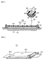
- FIG. 1 is a cross-sectional view illustrating an exhaustion of a bubble within an electrolyte layer in a method of manufacturing a bipolar battery in accordance with an embodiment of the invention.
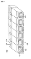
- FIG. 2 is a perspective view illustrating a bipolar battery manufactured using a method of manufacturing the bipolar battery in accordance with an embodiment of the invention.
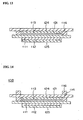
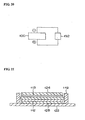
- FIG 3 is a cross-sectional view illustrating the bipolar battery shown in FIG. 2 .
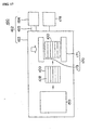
- FIG. 4 is a perspective view illustrating a battery assembly using the bipolar battery shown in FIG. 2 .
- FIG. 5 is a diagram of a vehicle wherein the battery assembly shown in FIG. 4 is mounted.
- a bipolar battery 10 manufactured using a method of manufacturing disclosed herein is, for example, a lithium secondary battery.
- the bipolar battery 10 comprises a bipolar electrode 110 having a cathode 113, an anode 112 and a collector 111.
- the bipolar battery 10 also includes an electrolyte layer 120, a first sealing layer (charging portion) 115 and a second sealing layer (charging portion) 117.
- the cathode 113 is formed at one side surface of the collector 111.
- the anode 112 is formed at the other side surface of the collector 111. That is, the collector 111 is placed between the cathode 113 and the anode 112.
- the first sealing layer 115 is arranged on the same side surface of the collector 111 as the cathode and extended to surround the cathode 113.
- the electrolyte layer 120 is arranged to cover the cathode 113 and the first sealing layer 115.
- the second sealing layer 117 is position-adjusted with the first sealing layer 115, thereby being arranged on the same side surface of the collector 111 as the anode 112 and extended to surround the anode 112.
- the electrolyte layer 120 has a layer wherein a gel polymer electrolyte penetrates into a porous separator 121 with permeability for segmenting the cathode and the anode as shown in FIG. 1 .
- the electrolyte layer 120 also has a layer of the electrolyte 124 for conducting an ion between the separator 121 and the cathode 113 or the anode 112.
- the collector 111 is, for example, a stainless steel foil. However, the collector 111 is certainly not limited thereto since it may include an aluminum foil, a clad material of nickel and aluminum, a clad material of copper and aluminum, or a plating material of a combination of the above metals.
- An anode active material of the anode 112 is, for example, a hard carbon (a non-graphitized carbon material).
- the anode active material is certainly not limited thereto since it may include a graphite-based carbon material or a lithium-transition metallic composite oxide.
- An anode active material composed of carbon and the lithium-transition metallic composite oxide provides optimum capacity and power.
- a cathode active material of the cathode 113 is, for example, LiMn 2 O 4 , although it is certainly not limited thereto.
- the lithium-transition metallic composite oxide provides optimum capacity and power.
- Thicknesses of the cathode 113 and the anode 112 are certainly not limited. That is, these thicknesses may be set depending on the purpose of use, such as emphasizing power or energy or emphasizing ion conductivity.
- a sealing material constituting the first and second sealing layers 115 and 117 shown in FIG. 3 is, for example, one-liquid uncured epoxy resin.
- the sealing material is certainly not limited thereto since it may include other thermosetting resins such as, for example, polypropylene or polyethylene or thermoplastic resins. Selection of a sealing material may be based on the type of application.
- a material of the separator 121 which is a part of the electrolyte layer 120, is PE (polyethylene) having porosity or permeability.
- PE polyethylene
- it is certainly not limited thereto since it may include, for example, other polyolefins such as PP (polypropylene), a stack in a three-layer structure of PP/PE/PP, polyamide, polyimide, aramide or non-woven fabric.
- the non-woven fabrics may include, for example, cotton, rayon, acetate, nylon and polyester.
- the separator 121 is an insulator for segmenting the cathode and the anode. However, since the electrolyte penetrates into numerous apertures of the separator 121, the ion and current can flow.
- An electrolytic solution of the electrolyte includes, for example, an organic solvent composed of PC (propylene carbonate) and EC (ethylene carbonate) and includes lithium salt (LiPF 6 ) as a support salt.
- the organic solvent is certainly not limited to PC and EC since it may include other ring-type carbonate classes, chain-type carbonate classes such as dimethylcarbonate and ether classes such as tetrahydrofuran.
- the lithium salt is also not limited to LiPF 6 since it may include other inorganic anionic salts and organic anionic salts such as LiCF 3 SO 3 .
- a host polymer of the electrolyte is, for example, PVDF-HFP (copolymer of polyvinylidene fluoride and hexafluoropropylene) containing 10% of HFP (hexafluoropropylene) copolymer.
- the host polymer is certainly not limited thereto since it may include other polymers without lithium ion conductivity or polymer (solid polymer electrolyte) with ion conductivity.
- the other polymers without lithium ion conductivity for example, include PAN (polyacrylonitile) and PMMA (polymethylmethacrylate).
- the polymer with ion conductivity for example, is PEO (polyethylene oxide) or PPO (polypropylene oxide).
- the bipolar battery 10 shown in FIG. 2 is housed within an exterior case 104 in the form of a stack 100 of unit batteries, as shown in FIG. 3 .
- the exterior case 104 serves to prevent an impact from the outside or environmental deterioration.
- Terminal plates 101 and 102 are arranged, respectively, at outermost (uppermost and lowermost) layers of the stack 100. Further, a reinforcing plate may be arranged at a further outer side of the terminal plates 101 and 102.
- the terminal plates 101 and 102 are composed of a high conductive member and configured to cover at least the entire electrode projection surface of the outermost layer of the stack 100. Therefore, a current extracting portion of the outermost layer acquires a low resistance, thereby reducing the resistance in the current extracting portion along a surface direction. Accordingly, it is possible to obtain the battery with a higher power.
- the high conductive member includes, for example, aluminum, copper, titan, nickel, stainless or alloys thereof.
- the terminal plates 101 and 102 are extended to an outer portion of the exterior case 104 and serve as an electrode tab for extracting the current from the stack 100.
- an electrode tab of an independent separate member By arranging an electrode tab of an independent separate member and connecting to the terminal plates 101 and 102 directly or by using a lead, it is possible to extract the current from the stack 100. It is also possible to constitute the terminal plates 101 and 102 with the collector 111 placed at an outermost layer of the stack 100.
- the exterior case 104 is composed of a sheet material such as polymer-metallic composite laminate film wherein metals such as aluminum, stainless, nickel and copper (including alloy thereof) are coated by an insulator such as a polypropylene film. Further, the exterior case 104 is formed by bonding a part or entire outer periphery of the case via thermal fusion.
- the exterior case 104 can be used independently.
- the battery assembly 136 constitutes serializing and/or parallelizing the exterior case 104 and multi-connecting the exterior cases 104.
- the battery assembly 136 has conductive bars 132 and 134. The conductive bars 132 and 134 are connected to the terminal plates 101 and 102 extended from an inner portion of the exterior case 104.
- a connecting method includes, for example, an ultrasonic welding operation, a thermal welding operation, a laser welding operation, a rivet operation, a caulking operation or an electronic beam.
- the battery assembly module 130 can provide greater power, it is possible, for example, to be mounted as a power source for driving a motor of a vehicle 138 (see FIG. 5 ).
- the vehicle includes, for example, an electric vehicle, a hybrid electric vehicle or an electric train.
- the battery assembly module 130 for example, can be elaborately controlled, such as controlling the charge in every exterior case 104 or every battery assembly 136. Accordingly, it is possible to achieve functional improvements such as an extension of driving distance per charging at one time or an extension of the lifetime of a battery mounted on a vehicle.
- FIG. 6 is a flow diagram of a method for manufacturing a bipolar battery.
- the method of manufacturing the bipolar battery of the first embodiment comprises the steps of forming an assembly unit as a sub-assembly unit wherein the electrolyte is applied to both surfaces of the bipolar electrode 110, overlapping the permeable separator with the electrolyte in any one of the bipolar electrodes 110, forming a bonded body by forming a stack of the assembly units (sub-assembly units) and assembling to house the stack within the exterior case.
- FIG. 7 is a flow diagram of the process for forming the assembly unit according to FIG. 6 .
- the process of forming the assembly unit comprises the steps of forming the electrode, arranging the electrolyte, arranging the first sealing material, arranging the separator material and arranging the second sealing material.
- FIG. 8 is a plan view and FIG 9 is a cross-sectional view of the electrode formed according to FIG. 7 .
- FIG. 10 is a cross-sectional view the electrolyte arranged according to FIG. 7 .
- FIG. 11 is a plan view and FIG. 12 is a cross-sectional view of the first sealing material arranged according to FIG. 7 .
- FIG. 13 is a cross-sectional view of a separator material arranged according to FIG. 7 .
- FIG. 14 is a cross-sectional view of a second sealing material arranged according to FIG. 7 .
- a cathode slurry is first prepared.
- the cathode slurry is prepared to have a cathode active material of 85 wt%, a conductive auxiliary agent of 5 wt% and a binder of 10 wt%.
- the cathode slurry obtains a desired viscosity by adding a viscosity adjusting solvent therein.
- the cathode active material is LiMn 2 O 4
- the conductive auxiliary agent is acetylene black
- the binder is PVDF (polyvinylidene fluoride)
- the viscosity adjusting solvent is NMP (N-methyl-2-pyrolidone).
- the cathode slurry is applied to one side surface of the collector 111 composed of, for example stainless steel foil.
- the conductive auxiliary agent for example, may include carbon black or graphite.
- the binder and the viscosity adjusting solvent are not limited to PVDF and NMP..
- an anode slurry is prepared.
- the anode slurry is prepared, for example, to have an anode active material of 90 wt% and a binder of 10 wt%.
- the anode slurry obtains a desired viscosity by adding the viscosity adjusting solvent therein.
- the anode slurry is applied to another side surface of the collector 111.
- the anode active material is hard carbon
- the binder and the viscosity adjusting solvent are PVDF and NMP.
- the anode slurry is applied to the other side surface of the collector 111.
- Applied membranes of the cathode slurry and the anode slurry are, for example, dried by using a vacuum oven to form the cathode 113 and the anode 112 (see FIG. 9 ). At this time, any NMP is removed by being volatilized. Thicknesses of the cathode 113 and the anode 112 are certainly not limited and may be set depending on the purpose of use (e.g., emphasis on power or energy) or on ion conductivity.
- the electrolytes 124 and 125 are applied to an electrode portion of the cathode 113 and the anode 112, respectively ( see FIG. 10 ).
- the electrolytes 124 and 125 are prepared to have an electrolytic solution of 90 wt% and host polymer of 10 wt%. These electrolytes 124 and 125 obtain a viscosity suitable for applying by adding a viscosity adjusting solvent therein.
- the electrolytic solution includes an organic solvent composed of PC (propylene carbonate) and EC (ethylene carbonate), and including lithium salt (LiPF 6 ) as a support salt.
- the concentration of the lithium salt is 1M, for example.
- the host polymer is PVDF-HFP (copolymer of polyvinylidene fluoride and hexafluoropropylene) containing 10% of HFP (hexafluoropropylene) copolymer.
- a viscosity preparing solvent is DMC (dimethyl carbonate). The viscosity preparing solvent is not limited to DMC.
- the collector 111 on which the cathode 113 and the anode 112 are formed is installed at a loading board so that the anode 112 side is the top surface. Then, the electrolyte 125 is applied to the anode 112. Thereafter, a protective film is adhered on the applied electrolyte 125 prior to inverting the bipolar electrode 110. This inversion can be easily performed by using an inverting device, which will be explained below. By providing the protective film, even if the bipolar electrode 110 is inverted, the electrolyte is protected when it becomes a bottom surface.
- the protective film is formed from resin such as polyethylene. The electrolyte is then applied to the cathode 113, which becomes the top surface after inversion.
- a single-liquid uncured epoxy resin is applied past the outer periphery of the cathode 113 on a portion of the exposed remainder of the collector 111 (see FIGS. 11 and 12 ).
- the application may be made with a dispenser, for example.
- the separator 121 is arranged to cover an entire cathode side surface of the collector 111 (see FIG. 13 ). To this end, the separator 121 is overlapped with the electrolyte and the first sealing material 114.
- separator arranging devices 240 and 340 which will be explained below, are used (see FIGS. 30 and 44 ).
- a single-liquid uncured epoxy resin as a charging material is arranged on the side of the separator 121 opposite the first sealing material 114 (see FIG. 14 ).
- application is made by a dispenser.
- the electrolyte 125 is provided on one side of the bipolar electrode 110.
- the assembly unit (sub-assembly unit) 108 is formed at the other side of the bipolar electrode 110.
- the electrolyte 124, the first and second sealing materials 114 and 116, and the separator 121 are sequentially installed.
- a thickness of the first sealing material 114 is predetermined to be less than a total thickness of the cathode 113 and electrolyte 124 according to one example.
- a thickness of the second sealing material 116 is predetermined to be less than a total thickness of the anode 112 and electrolyte 125 in certain examples. Specifically, since the separator 121 contacts a center portion wherein the electrolytes 124 and 125 are arranged prior to contacting the first and second sealing materials 114 and 116 arranged at the outer periphery, it is possible to restrain the remaining gas at the inner portion surrounded by the first and second sealing materials 114 and 116.
- FIG. 15 is a flow diagram of a process for forming a bonded body according to FIG. 7 .
- the process of forming the bonded body comprises the steps of setting the assembly unit, stacking, pressing, forming a sealing layer, forming an interface, initially charging and exhausting the gas.
- FIG. 16 is a cross-sectional view of an assembly unit set according to FIG. 15 .
- FIG. 17 is a diagram of a process for stacking and a process for pressing according to FIG. 15 .
- FIG 18 is a diagram of a sealing layer formed according to FIG 15 .
- FIG 19 is a diagram of a process for forming an interface according to FIG. 15 .
- FIG. 20 is a diagram of a process for initial charging according to FIG. 15 .
- the assembly unit 108 In the process of setting the assembly unit, a plurality of assembly units 108 are sequentially set in a magazine 150 shown in FIG 16 . At this time, the protective film is removed from the assembly unit 108. Further, the assembly unit 108 has an asymmetric top-bottom structure. Thus, the first sealing material 114 is merely installed at the bipolar electrode 110 in an uppermost assembly unit 108A. In a lowermost assembly unit 108B, the sealing material is also installed at the anode 112 side in addition to the constitution of the assembly unit 108. Also, the terminal plate 102 is arranged on the assembly unit 108A. Moreover, the terminal plate 101 is arranged beneath the assembly unit 108B.
- the magazine 150 has a clamp mechanism 152 in a frame shape and capable of embracing the outer peripheral portion of the assembly unit 108.
- the clamp mechanism 152 is arranged in a stacking direction with an interspacing such that the assembly units 108 do not contact each other.
- the stacking direction is vertical to a surface direction of the assembly unit 108.
- the clamp mechanism 152 is configured, for example, to have an elastic member composed of a spring and to be retainable and supportable when assigning a tensile force to the assembly unit 108 based on an elastic force such that corrugation is not generated.
- the magazine 150 is arranged within a vacuum treatment device 160, and the stack 100 of the assembly unit 108 is formed under vacuum.
- the vacuum operates within a range of 0.2 to 0.5 ⁇ 10 5 Pa. Because it is in a vacuum, the introduction of gas into a stacking interface of the electrode and the electrolyte layer can be eliminated. Because no bubble is introduced, ion movement is not restrained and battery resistance is not increased, thus creating a greater power density.
- the method of forming the stack 100 is certainly not limited to this description.
- the stack 100 may be formed by controlling the clamp mechanism 152 for holding the assembly unit 108 while moving the magazine 150 toward a cradle, as well as by sequentially releasing the assembly unit 108 when contacting the cradle.
- the vacuum treatment device 160 has a vacuuming means 162, a pressing means 170 and a controller 178.
- the controller 178 can be, for example, a microcomputer including a random access memory (RAM), a read-only memory (ROM) and a central processing unit (CPU) in addition to various input and output connections.
- RAM random access memory
- ROM read-only memory
- CPU central processing unit
- the control functions are performed by execution by the CPU of one or more programs stored in ROM.
- the vacuuming means 162 has a vacuum chamber 163, a vacuum pump 164 and a piping system 165.
- the vacuum chamber 163 has a detachable cover portion and a fixed base wherein the magazine 150 and the pressing means 170 are arranged.
- the vacuum pump 164 is, for example, centrifugal and is used to apply a vacuum to the vacuum chamber 163.
- the piping system 165 connects the vacuum pump 164 and the vacuum chamber 163, and a leak valve (not shown) is arranged therein.
- the pressing means 170 has a base plate 171 and a press plate 173, which are arranged so as to be close to and spaced apart from the base plate 171.
- the controller 178 is used for controlling the movement or pressing force of the base plate 173.
- an elastic body in a sheet-shape may be arranged on the base plate 171 and the press plate 173.
- the stack 100 is pressed by the press plate and the base plate 171 while maintaining a vacuum state (see FIG. 17 ). By doing so, the first and second sealing materials 114 and 116 are pressed to the desired thicknesses.
- the pressing pressure is, for example, 1 to 2 ⁇ 10 6 Pa.
- the stack 100 shown in FIG 18 is arranged in an oven 190 and then heated, thereby curing the first and second sealing materials 114 and 116 included in the stack 100, forming the first and second sealing layers 115 and 117.
- the heating temperature is, for example, 80°C.
- a method of heating the stack 100 is certainly not limited to using the oven.
- the thicknesses of the first and second sealing materials 114 and 116 are small, minimizing the contact between the outer atmosphere and the first and second sealing layers 115 and 117.
- thermoplastic resin may be applied to the first and second sealing materials 114 and 116.
- first and second sealing materials 114 and 116 are plasticized by heating to form the first and second sealing layers 115 and 117.
- the electrolytes 124 and 125 penetrate into the separators 121 and 122 included in the stack 100 and a gel interface is formed thereon (see FIG. 19 ).
- the heating temperature and pressing pressure are, for example, 80°C and 1 to 2 ⁇ 10 6 Pa.
- the pressing means 180 has a base plate 181, a press plate 183 arranged so as to be close to and spaced apart from the base plate 181, a lower portion heating means 185, an upper portion heating means 187 and a controller 188.
- the lower portion heating means 185 and the upper portion heating means 187 have a resistance heating element, for example, and they are arranged within the base plate 181 and the press plate 183 and used to increase the temperature of the base plate 181 and the press plate 183.
- the controller 188 is used for controlling the movement and pressing force of the press plate 183 as well as controlling the temperature of the lower portion heating means 185 and the upper portion heating means 187.
- the controller 188 can be, like the controller 178, a microcomputer including RAM, ROM and a CPU in addition to various input and output connections.
- one of the lower portion heating means 185 and the upper portion heating means 187 may be omitted.
- the lower portion heating means 185 and the upper portion heating means 187 may be arranged at an outer portion of the base plate 181 and the press plate 183.
- a sheet-shaped elastic body may be arranged in the base plate 181 and the press plate 183.
- a first charging operation is performed by a charging/discharging device 192 electrically connected to the stack 100, generating a bubble (see FIG 20 ).
- the initial charging condition is, for example, a capacity base approximately calculated from an application weight of the cathode, i.e., 4 hours in 21 V-0.5 C.
- the gas at a center portion of the stack 100 is moved to the outer periphery and is then removed by pressing a roller against a surface of the stack 100. This improves the power density of the battery.
- the integrated stack 100 is housed within the exterior case 104 (see FIG. 3 ) to thereby manufacture the bipolar battery 10 (see FIGS. 2 and 3 ).
- the exterior case 104 is formed by arranging the stack 100 between two sheet-shaped exterior materials and bonding an outer periphery of the exterior materials.
- the exterior materials are polymer-metallic composite laminate film coated by an insulator such as a polypropylene film and bonded by applying a thermal fusion.
- the process for forming the sealing layer and the process for forming the interface are integrated.
- the hardening of the first and second sealing materials 114 and 116 and the completing of the electrolyte layer are performed simultaneously. By doing to, it is possible to reduce the number of manufacturing steps.
- a process for attaching a tab (lead line) for monitoring a potential of each layer (bipolar unit battery) of the stack 100 may be added between the processes of forming the sealing layer and forming the interface.
- the first and second sealing materials 114 and 116 are arranged between the collector 111 and the separator 121 and extend to surround the cathode 113 and anode 112.
- a sealing structure is certainly not limited to the above.
- the gel polymer class electrolyte is a thermoplastic retaining the electrolyte within a polymer framework, liquid leakage is prevented, improving the bipolar battery reliability.
- the gel polymer class electrolyte is not limited to thermoplastic as, for example, it may be a thermoset. In such a case, the liquid leakage is prevented by hardening the electrolyte layer by pressing under heating to thereby prevent the liquid leakage.
- the surface pressure used in the pressing process is not limited to 1 to 2 ⁇ 10 6 Pa, as other pressures may be appropriately established by considering other material properties, such as the strength of materials that constitute the stack 100.
- the heating temperature in the process for forming the sealing layer is not limited to 80°C. It can be within a range between 60°C and 150°C, with the operational temperature determined by considering material properties such as the heat resistance of electrolytic solution or the hardening temperature of the sealing materials 114, 116.
- the electrolytes 124 and 124 are not limited to the gel polymer class since they may include the electrolytic solution class.
- the electrolytic solution in the process for arranging the electrolyte, for example, is applied to each electrode portion of the cathode 113 and anode 112 by using a micropipette and sank therein (see Fig. 10 ).
- the electrolytic solution includes an organic solvent composed of PC (propylene carbonate) and EC (ethylene carbonate), and includes a lithium salt (LiPF 6 ) as a support salt and a small quantity of surfactant.
- the concentration of the lithium salt is 1M, for example.
- the organic solvent is not limited to PC and PE since it may include other ring-type carbonate classes, chain-type carbonate classes such as dimethyl carbonate or ether classes such as tetrahyrdofuran.
- the lithium salt is not limited to LiPF 6 since it may include other inorganic anionic salts and organic anionic salts such as LiCF 3 SO 3 .
- FIG. 22 is a cross-sectional view of another modified example of an assembly unit 360.
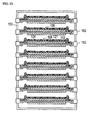
- FIG. 23 is a cross-sectional view illustrating a stacked body formed of the assembly units of FIG. 22 .
- the sizes may be somewhat exaggerated in some cases in order to easily explain the features.
- the separator 121 and the bipolar electrode 110 are shown to be thicker than they actually are. However, an end of the separator 121 is actually hung by its own weight.
- the electrolyte 124 may be optionally provided only at the cathode 113 side, rather than both the cathode 113 and anode 112 sides.
- the electrolyte 124 penetrates into the permeable separator 121 through to the opposite side of the separator 121, thereby penetrating the anode 112 to which the electrolyte is not provided.
- the bipolar battery 10 is manufactured having superior battery performance.
- the pressure within a vacuum container is 1 kPa or less.
- FIG. 24 is a perspective view of a pallet for loading the bipolar electrode.
- FIG. 25 is an exploded perspective view of the pallet.
- FIG. 26 is a cross-sectional view taken along the line A-A shown in FIG. 24 .
- An apparatus for manufacturing the bipolar battery comprises an inverting device 210, shown in FIGS. 27A-27C , for arranging the electrode, a separator feeding device 230, shown in FIGS. 28 and 29 , for arranging the separator material, and a separator arranging device 240, shown in FIG 30 .
- the pallet 270 has a pallet body portion 272 and a porous plate 279.
- an air exhausting groove 271 which becomes a path for suctioning the air, is formed in the pallet body portion 272.
- the porous plate 279 is fixed by a screw 273 in a surface wherein the air exhausting groove 271 of the pallet body portion 272 is formed.
- a vacuum lead-in aperture 274 communicating with the air exhausting groove 271 is formed on a side surface of the pallet body portion 272.
- a suction joint 276, which is formed on a leading end of an air tube hose 275 shown in FIG. 30 can be fitted into the vacuum lead-in aperture 274.
- the air tube hose 275 is connected to a vacuum pump (not shown).
- the porous plate may be a punching metal having a plurality of apertures, a foamed porous resin or a foamed porous metal.
- the suction joint 276 When the pallet 270 shown in FIG. 30 is moved by the conveyor 280, the suction joint 276 is formed on the leading end of the air tube hose 275, making it possible to move the pallet 270 while being connected to the suction joint 276.
- a driving source such as an actuator.
- the suction joint 276 may move forwardly and backwardly to connect with the vacuum lead-in aperture 274 of the pallet 270 in a process wherein a negative pressure must be applied to the pallet 270.
- the bipolar battery 110 is arranged on the pallet 270 such that the suction joint 276 is connected to the vacuum lead-in aperture 274, and the vacuum lead-in aperture 274 is communicated to a vacuum pump (not shown). By doing so, the bipolar electrode 110 is suctioned and positioned in the porous plate 279 of the pallet 270. Then, a gel electrolyte is applied to one surface of the bipolar electrode 110, and a protective film is adhered thereto. Thereafter, the bipolar electrode 110 is inverted. For such an inversion, it is desirable that an inverting device 210 be used.
- the inverting device 210 shown in FIG. 27 , has a first suction portion 211 for receiving the bipolar electrode 110 from the pallet 270 by suctioning the bipolar electrode 110 on the pallet 270.
- the inverting device 210 also has a second suction portion 212 for receiving the bipolar electrode 110 retained in the first suction portion 211.
- the first suction portion 211 has a curved first suction surface 213.
- the first suction surface 213 is configured to rotatably move while fitting the bipolar electrode 110 retained on the pallet 270 between the first suction portion 211 and the pallet 270 in a linear range having a desired width.
- a plurality of first suction apertures (not shown) is formed on the first suction surface 213.
- the first suction apertures can communicate with a vacuum pump (not shown) to thereby suction the bipolar electrode 110 arranged on the pallet 270.
- the suctioning force of the first suction portion 211 is set to be larger than that of the pallet 270 by adjusting a valve.
- the bipolar electrode 110 is moved to the first suction portion 211 while suctioning the bipolar electrode 110 to the pallet 270 (see FIG. 27A ).
- the bipolar electrode 110 is moved by the suctioning force difference while suctioning the bipolar electrode 110 from both the first suction portion 211 and the pallet 270.
- the generation of a corrugation in the bipolar electrode 110 can be prevented.
- the second suction portion 212 has a curved second suction surface 215 wherein a plurality of second suction apertures is formed.
- the second suction apertures can communicate with a vacuum pump (not shown).
- the second suction portion 212 is configured to rotate while fitting the bipolar battery 110 between the first suction surface 213 and the second suction portion 212 in a linear range having a desired width (see FIG. 27B ).
- a suctioning force of the second suction portion 212 may be set to be greater than that of the first suction portion 211 by adjusting a valve so that the first suction portion 211 and the second suction portion 212 are rotated in opposite directions while contacting the second suction portion 212 to the bipolar electrode 110 retained in the first suction portion 211. By doing so, the bipolar electrode 110 retained in the first suction portion 211 can be moved to the second suction portion 212.
- the second suction portion 212 is rotatably moved to the pallet 270 while retaining the bipolar electrode 110, thereby moving the bipolar electrode 110 to the pallet 270 (see FIG 27C ). At this time, the suctioning force of the pallet 270 is set to be greater than that of the second suction portion 212.
- the bipolar electrode 110 is moved while suctioning with a suctioning force, which is larger than a side to be suctioned.
- a suctioning force which is larger than a side to be suctioned.
- the bipolar electrode 110 can be inverted without generating the corrugation in the very thin bipolar electrode 110.
- the separator feeding device 230 comprises a separator roll 231 wherein the separator is rolled into a roll shape, a guide roller 232 for guiding the separator 121 extracted from the separator roll 231, a separator loading board 233 on which the extracted separator 121 is loaded, a cutting blade 234 for cutting the separator 121 in a desired length by moving forward and backward with respect to the extracted separator 121 and a separator extracting portion (not shown) for extracting the separator 121 by holding the separator 121.
- the separator roll 231 is rotatably installed on a roll support 235, which is fixedly installed. Further, a servo motor 236 is connected to the separator roll 231 via a decelerator 237, and its rotation is controlled by another controller (like the controllers 178 and 188).
- the separator 121 is held by a separator extracting portion (not shown) and extracted on the separator loading board 233.
- the separator extracting portion can hold the separator by holding or suctioning.
- the cutting blade 234 is moved forward and/or backward along the separator 121 to cut the separator 121 to a desired length.
- the cut separator 121 is suctioned and retained by the separator arranging device 240, which is explained below.
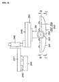
- FIG 30 is a perspective view of the separator arranging device in accordance with the first embodiment, while FIG. 31 is a front view and FIG 32 is a side view.
- FIG. 33 is a front view of the suction body portion taken along the line B-B shown in FIG 32 .
- FIG. 34 is a front view of the separator suction portion taken along the line C-C shown in FIG 32 .
- FIG. 35 is a conceptual view schematically illustrating the separator suction portion.
- FIG. 36 is an enlarged side view of the surroundings of the separator suction portion of the separator arranging device. Fig.
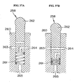
- FIG. 37A is a cross-sectional view of a plunger valve at a time when the valve is opened
- FIG 37B is a cross-sectional view at the time when the valve is opened to the outside.
- FIG. 38 is a partial side view of the separator suction portion when all the plunger valves are opened
- FIG. 39 is a partial side view of the separator suction portion when some of the plunger valves are opened.
- FIG 40 is a partial side view of the separator suction portion when all the plunger valves are opened to the outside.
- FIG. 41 is a side view of the separator suction portion when installing the separator.
- the separator arranging device 240 in FIG 30 is configured to arrange the separator 121 in the bipolar electrode 110 on which the electrolyte is applied.
- the separator arranging device 240 comprises a separator suction portion 242 for suctioning the separator 121 and having a separator suctioning surface 241 that is curved so as to protrude toward the pallet 270 on the conveyor 280.
- the separator arranging device 240 also includes a moving mechanism 243 for moving the separator suction portion 242 in a three-dimensional direction.
- the separator arranging device 240 includes a rotating mechanism 244 for rotating the separator suction portion 242.
- the separator arranging device 240 serves as a bubble exhausting mechanism.
- the moving mechanism 243 shown in FIGS. 30 and 31 comprises a frame body 245 fixedly installed over the conveyor 280, a horizontal moving member 247 moveably installed in a guide rail 246 installed and extended on the frame body 245 along a horizontal direction intersecting with the conveyor 280, a lifting member 249 liftable by a cylinder 248 to which a guide installed in the horizontal moving member 247 is attached and a suction portion retaining member 251 moveable along a moving direction of the conveyor 280 by a servo linear actuator 250 installed in the lifting member 249.
- the suction portion retaining member 251 is provided with the separator suction portion 242, which is rotatable by a rotating shaft extended along a horizontal direction intersecting with the conveyor 280.
- the rotating mechanism 244 is installed in the suction portion retaining member 251 and has a servo motor 253 connected to the separator suction portion 242 via the decelerator 252. By controlling the rotating mechanism 244 by a controller, it is possible to freely move the separator suction portion 242 around the rotating shaft.
- the separator suction portion 242 comprises a suction body 256 having a flow path forming surface 255 shown in detail in FIG. 33 wherein an air flow path groove 254, which becomes a path for suctioning the air, is formed and has a curved portion 257.
- the curved portion 257 of the separator suction portion 242 forms the surface of the separator suction surface 241 opposite to the flow path forming surface 255 (see FIGS. 32 and 34 ).
- the air flow path groove 254 formed in the flow path forming surface 255 of the suction body 256 is divided into a plurality of suction areas R1 to R4 arranged in one direction, as shown in FIG. 35 . As shown in FIG.
- each suction area R1 to R4 is connected to each separate plunger valve 258A, 258B, 258C and 258D via connecting tubes 268A, 268B, 268C and 268D. Therefore, the air suction groove 254 of each suction area R1 to R4 is capable of suctioning separately. Also, in this embodiment, although there are four suction areas R1 to R4, embodiments are not limited to this number of suction areas. Further, as the number of suction areas increases, a vacuum destroying area explained below can be more finely set.
- the curved portion 257 has a curved shape, which is bent at both end sides of the arranging direction of the suction areas R1 to R4.
- a plurality of separator suction apertures 259 are formed in the curved portion 257 wherein the apertures 259 penetrate from the flow path forming surface 255 (shown in FIG. 33 ) to the separator suction surface 241 (shown in FIG. 32 ).
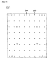
- the separator suction apertures 259 are formed over substantially the entire surface of the separator suction surface 241 and have a diameter of 3 mm and a pitch of 20 mm.
- Each separator suction aperture 259 is communicated with the air flow path groove 254 of the suction body 256 (shown in FIG. 33 ).
- the curved portion 257 with a material having permeability such as a foamed porous resin or a foamed porous metal without forming the separator suction aperture 259 in the curved portion 257.
- the flow path forming surface 255 may be curvedly formed so that a curved punching metal having a uniform plate thickness may be applied as the curved portion 257 installed in the flow path forming surface 255.
- a cylindrical valve forming portion 260 is fixed wherein the valve is formed as shown in FIG. 36 .
- the separator suction portion 242 and the valve forming portion 260 are rotatably connected to the suction portion retaining member 251.
- a slide moving portion 262 is installed as shown in FIGS. 37A and B .
- the slide moving portion 262 can move forward and backward along a diametrical direction and is pressed by a spring 261.
- a flow path 265 communicating with a vacuum pump 269 is connected to a flow path 264 communicating with the separator suction groove 259 by opening a valve (see FIG 37A ).
- a flow path 263 opened to the atmosphere is connected to the flow path 264 (see FIG. 37B ).
- the plunger valves 258A to 258D are installed at each suction area R1 to R4.
- Each plunger valve 258A to 258D is arranged side by side along a peripheral direction in the same order as the suction areas R1 to R4.
- a pushing portion 266 is installed at the suction portion retaining member 251 shown in FIG. 36 .
- the pushing portion 266 covers a desired angular range in the outer periphery of the valve forming portion 260 as shown in FIGS. 38 and 39 .
- the pushing portion 266 is configured to push the slide moving portion 262 installed in the valve forming portion 260 by a taper portion 267 formed at an end and to retain the slide moving portion 262 as contacted.
- the separator 121 When installing the separator 121, the separator 121 as fed by the separator feeding device 230 is suctioned and retained with a negative pressure generated in the separator suction portion 242. At this time, all the plunger valves 258 are opened, and the separator 121 is suctioned by all the suction areas R1 to R4.
- the curved portion 257 is rotated and moved over the bipolar battery 110 arranged on the pallet 270 along an arrangement direction of the suction areas R1 to R4 shown by the unlabeled arrow in FIG. 41 .
- the curved portion 257 is moved along the arrangement direction of the suction areas R1 to R4 while a spaced surface S spaced apart from the pallet 270 in a desired distance L linearly contacts the separator suction surface 241.
- a contact moving distance X1 is that in which a linearly contacted position P in the spaced surface S is moved along the arrangement direction of the suction areas R1 to R4.
- the contact moving distance X1 is equal to a separator contact length X2 of a linearly contacted area of the separator suction surface 241 along the arrangement direction of the suction areas R1 to R4. While a member fitted onto the pallet 270 is subjected to a sandwiching force from the separator suction surface 241 vertical to the pallet 270, the member is not subjected to a force horizontal to the pallet 270. Accordingly, the separator 121 is not offset from the pallet 270 and conveyor 280.
- the desired distance L between the pallet 270 and the separator suction surface 242 is set such that the separator 121 retained by the separator suction surface 242 contacts the electrolyte applied to the bipolar electrode 110 installed on the pallet 270. Therefore, the separator 121 retained by the separator suction portion 242 contacts the electrolyte at a lowermost portion of the separator suction portion 241 (the nearest portion to the pallet 270) in a linear shape having a desired width.
- the slide moving portion 262 of the plunger valves 258A to 25 8D is pushed one by one while the separator suction portion 242 is rotated.
- the suctioning is sequentially stopped from a suction area for suctioning a region contacting the electrolyte 124 of the separator, thereby releasing the vacuum.
- the electrolyte 124 of the separator 121 is moved to the bipolar electrode 110 side.
- the separator 121 is linearly contacted with the electrode having a desired width at the lowermost portion of the separator suction surface 242, and the bubble N between the separator 121 and the electrolyte can be exhausted.
- the separator 121 when exhausting the bubble N, the separator 121 does not need to be tightly pulled by hand, thereby avoiding damage to the separator 121.
- the electrolyte can be densely penetrated into the separator 121, and the ion and current can efficiently flow when operating the battery, increasing the power density.
- the bipolar electrode 110 is suctioned and retained by the pallet 270 in the process of installing the separator 121. However, depending on conditions, it may not be necessary to suction.
- FIG. 42 is a front view and FIG. 43 is a side view of another example of the separator feeding device. Further, the members having the same function as the above explained separator suction device are denoted by the same reference numerals and an explanation thereof is omitted.
- the separator loading board 233 shown in FIGS. 28 and 29 may not be provided. Alternately, it is configured to directly load the separator 121 on the separator suction portion 242, which is retained by allowing the separator suction surface 241 to be a top surface.
- the separator suction portion 242 is retained and fixed in a separator suction portion fixing member 290. Then, the suction areas (such as R1 to R4 shown in FIG. 35 ) of the separator suction portion 242 are suctioned to retain the separator 121 on the separator suction surface 241. Thereafter, the separator suction portion 242 is inverted, and the separator suction portion 242 is fixed to the moving mechanism 243. Then, the separator is reinstalled.
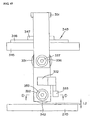
- FIG. 44 is a front view and FIG. 45 is a side view of a separator arranging device of the apparatus for manufacturing the bipolar battery of the second embodiment.
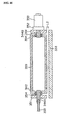
- FIG. 46 is a cross-sectional view of the suction roller taken along the line D-D shown in FIG. 45 .
- the apparatus for manufacturing the bipolar battery 300 of the second embodiment is different from the first embodiment in terms of a separator arranging device 340 used to arrange the separator material.
- a separator arranging device 340 used to arrange the separator material.
- Members having the same function as in the first embodiment are denoted by the same reference numerals and explanations thereof will be omitted.
- the separator arranging device 340 of the second embodiment comprises a cylindrical suction roller 342 (separator suction portion) having a rotational axis parallel to the pallet 270, a separator roll 331 for feeding the separator 121 to the suction roller 342 and a moving mechanism 343 for moving the suction roller 342 to a two-dimensional direction.
- the separator arranging device 340 serves as a bubble exhausting mechanism.
- the moving mechanism 343 comprises a frame body 345 extended over the conveyor 280 along a traveling direction of the conveyor 280, a horizontal moving member 347 moveably installed in a guide rail 346 extending along a traveling direction of the conveyor 280 in the frame body 345 and a lifting member 349 liftable by a surface pressure control cylinder 348 installed at the horizontal moving member 347.
- a suction portion retaining member 351 is fixed to the lifting member 349.
- the separator roll 331 and the suction roller 342 are connected to the suction portion retaining member 351. Accordingly, by controlling the moving mechanism 343 through a controller, the separator roll 331 and the suction roller 342 can be freely moved to two directions in an up-down direction and a traveling direction of the conveyor.
- the separator roll 331 is rotatably installed in the suction portion retaining member 351 by a rotational shaft, which is extended along a horizontal direction intersecting with the conveyor 280.
- a servo motor 336 is connected to the separator roll 331 via a decelerator 337.
- the separator roll 331 can be rotated by controlling the servo motor 336 through a controller.
- a separator pressing portion 333 is installed in the suction portion retaining member 351.
- the separator pressing portion 333 is configured to fit the separator 121 between the separator pressing portion 333 and the suction roller 342, while closing and distancing away from the suction roller 342 by a separator pressing driving cylinder 332 fixed on the suction portion retaining member 351.
- the separator pressing portion 333 is spaced away to allow the separator 121 to be moved. While the separator 121 is not fed, the separator 121 is fitted and retained between the suction roller 342 and the separator pressing portion 333.
- the suction roller 342 is rotatably installed at the suction portion retaining member 351 by rotational shafts 344A and 344B shown in FIG. 46 , which are extended along a horizontal direction intersecting with the conveyor 280.
- a servo motor 353 is connected to the suction roller via a decelerator 352. The suction roller 342 can be rotated by controlling the servo motor 353 through a controller.
- the suction roller 342 is connected to the rotational shafts 344A and 344B, which are fixed on the suction portion retaining member 351 via a bearing 354.
- One rotational shaft 344A is hollow and is connected to an air suction tube 355.
- the air suction tube communicates with an inside of the suction roller 342 at one end and with a vacuum pump via a valve at the other end.
- a plurality of separator suction apertures 359 is formed in the suction roller 342.
- the plurality of separator suction apertures 359 penetrates from an inner surface to an outer surface of the suction roller 342 and can suction the air outside of the suction roller to the inside.
- the suction roller 342 can be moved in parallel while retaining a desired distance L2 between the outer surface and the pallet 270 (see FIG. 45 ).
- a leading end of the separator 121 is first placed at an end of the bipolar electrode 110 and fixed using a clamp. Then, the suction roller 342 is arranged thereon. Thereafter, the suction roller 342 is rotated and moved while being suctioned by the suction roller 342. At this time, the moving distance of the suction roller 342 is equal to the total circumferential length of the rotated suction roller 342.
- the desired distance L2 between the pallet 270 and an outer peripheral surface of the suction roller 342 is set such that the separator 121 retained in the suction roller 342 is contacted with the electrolyte applied to the bipolar electrode 110 installed in the pallet 270.
- the separator 121 retained in the suction roller 342 linearly contacts the electrolyte at a lowermost portion of the suction roller 342, nearest the pallet 270, having a desired width.
- the separator 121 linearly contacts the electrolyte 124 at the lowermost portion of the separator suction surface 241 having a desired width to thereby increase the contact area, restricting the introduction of a bubble N between the separator 121 and the electrolyte 124.
- the permeability of the separator 121 permits a suctioning force to be exerted from one side M1 of the separator 121 to another side M2 to thereby exhaust the bubble N (see FIG. 1 ).
- the electrolyte 124 contacting the separator 121 densely penetrates into the separator due to the suctioning force, further limiting bubble N formation between the separator 121 and the electrolyte 124 and improving the bipolar battery 10 performance.
- the separator feeding device 230 of the first embodiment is unnecessary.
- FIG. 47 is a side view of a separator arranging device of an apparatus for manufacturing the bipolar battery of the third embodiment.
- FIG. 48 is a cross-sectional view taken along the line E-E shown in FIG. 47 .
- FIG. 49 is a cross-sectional view taken along the line F-F shown in FIG 47 .
- FIG 50 is a cross-sectional view taken along the line G-G shown in FIG. 47 .
- the separator 121 is arranged on a separator retaining plate 402 and the bipolar electrode 110 is installed on the separator 121.
- the processes of arranging the electrolyte, the first sealing material, the separator material and the second sealing material are performed on the pallet 270 for every bipolar electrode 110.
- the process of arranging the separator material is performed on another separator retaining plate 402.
- the members having the same function as in the first and second embodiments are denoted by the same reference numerals and explanations thereof will be omitted.
- a separator arranging device 401 of the third embodiment comprises a separator retaining plate 402 for retaining the separator 121, a conveyor for loading and conveying the separator retaining plate 402 and a pressing portion 404 installed at a desired position on the conveyor 403 and capable of pressing and moving away from the separator retaining plate 402 loaded on the conveyor 403.
- the separator arranging device 401 serves as a bubble exhausting mechanism.
- the separator retaining plate 402 is a planar permeable plate and is formed from a punching metal, foamed porous resin or foamed porous metal.
- Convey rollers 405 are installed at the conveyor 403, wherein the convey rollers are connected to a motor so as to rotate.
- the separator retaining plate 402 can be conveyed by rotating the convey roller 405.
- the pressing portion 404 can press and move away from the separator retaining plate 402 loaded on the conveyor 403.
- the separator 121 is installed at the separator retaining plate 402 arranged on the conveyor 403. Then, the bipolar electrode 110 is overlapped with the separator 121 such that a side at which the first sealing material 114 is installed is contacted with the separator 121, wherein the electrolytes 124 and 125 are applied to both electrodes of the bipolar electrode 110 and the first sealing material 114 is applied to one side surface of the bipolar electrode 110.
- the arrangement of the separator 121 and the bipolar electrode 110 is performed by a robot or by hand.
- the convey roller 405 After the convey roller 405 is driven to move the separator retaining plate 402 to a position wherein the pressing portion 404 is installed, the convey roller 405 is stopped. Thereafter, as shown in FIG. 50 , the pressing portion 404 is driven to press the bipolar electrode 110 loaded on the separator retaining plate 402 against the separator 121. To this end, since the bubble N is pressed out from one side M1 toward another side M2 of the separator 121, and since the separator retaining plate 402 and the separator 121 have permeability, the bubble N within the electrolyte 124 and the separator 121 is exhausted to a fine aperture of the separator retaining plate 402 at an opposite side via the separator 121 ( see FIG. 1 ). Further, at this time the electrolyte 124 contacting the separator 121 is penetrated into the separator 121 by a pressing force.
- the electrolyte 125 When pressing by the pressing portion 404, it is preferable in certain embodiments to adhere, for example, a PET film to the electrolyte 125 of the bipolar electrode 110 since the electrolyte 125 is also applied on a side contacting the pressing portion 404 of the bipolar electrode 110.
- the electrolyte 125 may not be applied on a side contacting the pressing portion 404 of the bipolar electrode 110 when pressing. If this is so, the PET film is.unnecessary.
- the pressing portion 404 is driven by a cylinder, a motor or by hand.
- the pressing force is approximately 400 Pa, but is not specifically limited thereto.
- the bipolar electrode 110 is released from the pressing force by retracting the pressing portion 404.
- the convey roller 405 is driven to export the bipolar electrode 110 to a next process, i.e., a process for arranging the second sealing material.
- the bubble N is pressed out from one side M1 to another side M2 of the separator 121 by a pressing operation rather than by a suctioning operation, thereby exhausting the bubble N through the separator 121 (see FIG. 1 ). Accordingly, since the introduction of the bubble N between the separator 121 and the electrolyte 124 can be prevented, a bipolar battery 10 with superior battery performance is manufactured. Further, when removing the bubble N, there is no need to tightly pull the separator 121 by hand so as to remove the bubble N. Thus, the separator 121 will not be damaged, and the electrolyte can be densely penetrated into the separator 121.
- the ion and current can efficiently flow when operating the battery, increasing the power density. Also, since the separator 121, which has a poor handling feature, is previously arranged on the separator retaining plate 402 with the bipolar electrode 110, which has a good handling feature, the positioning workability is good. In addition, unlike the first and second embodiments, since the suction device is not necessary, a small scale facility can be used, thereby reducing the costs associated with the facility. A detaching connector such as a suction hose is also not required at the separator retaining plate, thereby decreasing failures and increasing reliability of the facility.
- FIG. 51 is a side view of a separator arranging device of the apparatus for manufacturing the bipolar battery.
- FIG 52 is a cross-sectional view taken along the line H-H shown in FIG. 51 .
- FIG. 53 is a cross-sectional view taken along the line I-I shown in FIG 51 .
- FIG. 54 is a side view of a separator retaining plate of the fourth embodiment.
- the separator 121 is installed at the bipolar electrode 110 arranged in the pallet 270.
- the separator 121 is arranged in a separator retaining plate 502 and the bipolar electrode 110 is installed at the separator 121 similar to the third embodiment.
- the members having the same function as in the first to third embodiments are denoted by the same reference numerals and explanations thereof will be omitted.
- a separator arranging device 501 of the fourth embodiment comprises a separator retaining plate 502 for retaining the separator 121, a conveyor 403 for loading and conveying the separator retaining plate 502 and first and second negative pressure supplying portions 503A and 503B for supplying the negative pressure to the separator retaining plate 502.
- the separator arranging device 501 serves as a bubble exhausting mechanism.
- a permeable venting portion 504 is formed on the separator retaining plate 502 in a center portion of a planar plate.
- An outer portion 506 is formed on one side surface of the separator retaining plate 502.
- the outer portion 506 is connected to the separator retaining plate 502 at an outer periphery of the venting portion 504 to form a suction space 505 between the outer portion 506 and the venting portion 504.
- a through-hole portion 507 is formed at the outer portion 506 in a position opposite to the venting portion 504.
- the venting portion is formed from a punching metal, foamed porous resin or foamed porous metal.
- the first and second negative pressure supplying portions 503A and 503B are connected to a vacuum pump (not shown) via a three-way valve (not shown). They can supply the negative pressure from a negative pressure supply aperture 508, which is formed adjacent to a bottom surface of the separator retaining plate 502 installed at the conveyor 403. It is preferred, but not necessary, that the pallet 270 used in the first and second embodiments be employed as the separator retaining plate 502. It is also possible to use a permeable conveyor belt as the separator retaining plate 502.
- the separator 121 is installed at the separator retaining plate 502 arranged at the conveyor 403.
- the through-hole portion 507 of the separator retaining plate 502 conforms to the negative pressure supplying aperture 508 of the first negative pressure supplying portion 503A.
- the negative pressure is supplied to the suction space 505 via the first negative pressure supplying portion 503A. This is so that the negative pressure is generated at an outer side (the separator 121 side) of the venting portion 504, and the separator 121 is suctioned to the venting portion 504.
- a corrugation of the separator 121 can be elongated.
- the bipolar electrode 110 is contacted with the separator 121. This is so that a side at which the first sealing material 114 is provided is contacted with the separator 121.
- the electrolytes 124 and 125 are applied to both electrodes of the bipolar electrode 110, and the first sealing material 114 is applied to one side surface of the bipolar electrode 110.
- the arrangement of the separator 121 and the bipolar electrode 110 is performed by a robot or by hand.
- the negative pressure is supplied to the suction space 505 by the second negative pressure supplying portion 503B via the through-hole portion 507.
- the separator retaining plate 502 and the separator 121 are permeable, the bubble N within the electrolyte 124 and the separator 121 is suctioned and exhausted by the separator 121 and the venting portion 504 (see FIG. 1 ).
- the electrolyte 124 contacting the separator 121 densely penetrates into the separator 121.
- it is effective to perform a roller operation from the bipolar electrode side or to press the bipolar electrode 110 against the separator 121 as in the third embodiment.
- the convey roller 405 is driven to export to the next process, i.e., the process of arranging the second sealing material.
- a suctioning force is exerted from one side M1 to another side M2 of the separator by suctioning the separator 121, rather than by pressing as in the third embodiment.
- This exhausts the bubble N through the separator 121. Therefore, since the introduction of the bubble N at an inner side of the separator 121 and the electrolyte 124 can be prevented, a bipolar battery 10 is provided with superior battery performance. Further, when exhausting the bubble N, there is no need to tightly pull the separator 121 by hand so as to remove the bubble N. Thus, the separator 121 will not be damaged.
- the electrolyte can be densely penetrated into the separator 121, and the ion and current can efficiently flow when operating the battery. Thus, it is possible to increase the power density. Further, it is possible to use a permeable belt conveyor wherein a suction space is formed at an inner peripheral side. This is so that the belt is used as the separator retaining plate.
- the order of stacking the first and second sealing materials 114 and 116 or the separator 121 is determined to prepare the assembly unit 108 shown in FIG. 14 .
- the order or constitution of stacking operations is certainly not limited thereto. It may be preferable to apply a process of arranging the separator 121 in the cathode 113 or the anode 112 wherein the electrolytes 124 and 125 are applied.
Landscapes
- Chemical & Material Sciences (AREA)
- Chemical Kinetics & Catalysis (AREA)
- Electrochemistry (AREA)
- General Chemical & Material Sciences (AREA)
- Engineering & Computer Science (AREA)
- Manufacturing & Machinery (AREA)
- Physics & Mathematics (AREA)
- Condensed Matter Physics & Semiconductors (AREA)
- Dispersion Chemistry (AREA)
- General Physics & Mathematics (AREA)
- Inorganic Chemistry (AREA)
- Secondary Cells (AREA)
Claims (17)
- Procédé de fabrication d'une batterie bipolaire (10), la batterie (10) comprenant une électrode bipolaire (110) comprenant une cathode (113), une anode (112) et un collecteur (111) prévu entre la cathode (113) et l'anode (112), le procédé comprenant les étapes consistant :à appliquer un électrolyte (124) sur au moins l'une de la cathode (113) et de l'anode (112) sur un côté opposé au collecteur ; où l'électrolyte (124) est un électrolyte en gel polymère ou une solution électrolytique ;à superposer un séparateur perméable (121) sur l'électrolyte (124) ; età évacuer une bulle d'air (N) formée entre l'électrode bipolaire (110) et le séparateur perméable superposé (121) en faisant pénétrer une partie de l'électrolyte (124) à travers le séparateur perméable (121).
- Procédé selon la revendication 1, dans lequel l'étape consistant à évacuer la bulle d'air (N) comprend le fait d'exercer une pression négative avec un dispositif d'aspiration qui assure l'aspiration à la partie d'aspiration de séparateur sur le séparateur (121) lors de la superposition.
- Procédé selon la revendication 1, comprenant en outre le fait :de former un empilement (100) en empilant une pluralité des électrodes bipolaires (110) superposées avec le séparateur (121) les unes sur les autres.
- Procédé selon l'une des revendications 1 à 3, comprenant en outre le fait :de retenir le séparateur (121) dans une plaque de retenue de séparateur (402) configurée de manière à être perméable ; etde superposer l'électrode bipolaire (110) avec le séparateur (121) ;dans lequel l'évacuation de la bulle d'air (N) comprend le fait de presser l'électrode bipolaire (110) contre le séparateur (121) retenu dans la plaque de retenue de séparateur (402).
- Procédé selon la revendication 4, dans lequel le fait de presser l'électrode bipolaire (110) contre le séparateur (121) exerce une pression négative à partir d'un côté de surface arrière de la plaque de retenue de séparateur (402) dans laquelle le séparateur (121) est retenu.
- Procédé selon l'une des revendications 1 à 3, comprenant en outre le fait :d'aspirer et de retenir une surface latérale du séparateur (121) avec une partie d'aspiration de séparateur (242) ;de retenir l'électrode bipolaire (110) sur un convoyeur (280), avec l'électrode bipolaire (110) configurée avec une surface d'électrolyte orientée vers le haut ; etde superposer une surface latérale du séparateur (121) opposée à la partie d'aspiration de séparateur (242) avec la surface d'électrolyte ;dans lequel l'évacuation de la bulle d'air (N) comprend le fait d'exercer une pression négative avec un dispositif d'aspiration (254, 258A-D, 268A-D) qui assure l'aspiration à la partie d'aspiration de séparateur (242) sur le séparateur (121) lors de la superposition.
- Procédé selon l'une des revendications 1 à 3, comprenant en outre le fait :d'aspirer une surface latérale du séparateur (121) avec une partie d'aspiration de séparateur (342), où la partie d'aspiration de séparateur (342) est un rouleau d'aspiration (342) ayant un espace interne en communication avec un dispositif d'aspiration (350), le rouleau d'aspiration (342) ayant une pluralité d'ouvertures d'aspiration (359) à travers lesquelles le dispositif d'aspiration (350) aspire le séparateur (121) ;de retenir l'électrode bipolaire (110) sur un convoyeur (280), l'électrode bipolaire (110) étant configurée avec une surface d'électrolyte orientée vers le haut ;de superposer une surface latérale du séparateur (121) opposée à la partie d'aspiration de séparateur (342) avec la surface d'électrolyte ; et où l'évacuation de la bulle d'air (N) comprend le fait d'exercer une pression négative avec le rouleau d'aspiration (342) sur le séparateur (121) lors de la superposition.
- Procédé selon l'une des revendications 1 à 7, dans lequel l'électrode bipolaire (110) comprend une cathode (113) formée sur un côté d'un collecteur (111) et une anode (112) formée sur un côté opposé du collecteur (111) ; la batterie bipolaire (10) comprenant en outre :une partie de charge (115, 117) dans laquelle un matériau de charge est agencé dans un espace entre le collecteur (111) et le séparateur (121) afin d'entourer la cathode (113) et l'anode (112).
- Batterie bipolaire (10) formée par le procédé selon l'une des revendications précédentes, la batterie comprenant :une couche d'électrolyte (120)une électrode bipolaire (110) comportant une cathode (113) formée sur un côté d'un collecteur (111) et une anode (112) formée sur un côté opposé du collecteur (111), la cathode (113) et l'anode (112) étant recouvertes en surface avec un électrolyte (124) sur un côté opposé au collecteur (111) ;dans laquelle une surface d'électrolyte de l'électrode bipolaire (110) est mise en contact avec un séparateur perméable (121) et une partie de l'électrolyte (124) s'infiltre dans le séparateur (121), formant ainsi la couche d'électrolyte (120), et une bulle d'air (N) générée lors du contact avec le séparateur (121) est évacuée de la batterie (10).
- Batterie bipolaire (10) selon la revendication 9, dans laquelle la batterie bipolaire (10) comprend en outre :une partie de charge (115, 117) dans laquelle un matériau de charge est agencé dans un espace entre le collecteur (111) et le séparateur (121) afin d'entourer la cathode (113) et l'anode (112).
- Appareil de fabrication d'une batterie bipolaire selon la revendication 9, comprenant un mécanisme d'évacuation de bulles (240, 340, 401, 501) pour évacuer une bulle d'air (N) formée entre une électrode bipolaire (110) et un séparateur perméable superposé (121) à travers le séparateur (121), où le mécanisme d'évacuation de bulles (240, 340, 401, 501) comprend au moins un élément parmi :une plaque de retenue de séparateur (402, 502) pour retenir le séparateur (121), la plaque de retenue de séparateur (402, 502) étant perméable de sorte que la bulle d'air (N) évacuée à travers le séparateur (121) soit évacuée vers l'extérieur ;une partie de pression (404) pour presser le séparateur (121) retenu sur la plaque de retenue de séparateur (402, 502) contre l'électrode bipolaire (110)une partie fournissant une pression négative (503A, 503B) pour exercer une pression négative sur le séparateur (121) à travers la plaque de retenue de séparateur (402, 502).
- Appareil de fabrication d'une batterie bipolaire selon la revendication 9, comprenant un mécanisme d'évacuation de bulles (240, 340, 401, 501) pour évacuer une bulle d'air (N) formée entre une électrode bipolaire (110) et un séparateur perméable superposé (121) à travers le séparateur (121), où le mécanisme d'évacuation de bulles (240, 340, 401, 501) comprend :une partie d'aspiration de séparateur (242, 342) configurée pour aspirer et retenir une surface latérale du séparateur (121), où le séparateur (121) aspiré et retenu est superposé avec la surface d'électrolyte précédemment fournie à la cathode (113) ou à l'anode (112) et aspiré pour évacuer la bulle d'air (N) à travers le séparateur (121).
- Appareil selon la revendication 11, dans lequel la plaque de retenue de séparateur (402, 502) est formée à partir d'un métal de poinçonnage, d'une résine poreuse sous forme de mousse ou d'un métal poreux sous forme de mousse.
- Appareil selon la revendication 12, comprenant en outre :un mécanisme de déplacement (243, 343) couplé à la partie d'aspiration de séparateur (242, 342), positionné sur un convoyeur (280) et configuré pour se déplacer de manière linéaire sur le convoyeur (280) ;dans lequel le mécanisme de déplacement (243, 343) positionne la partie d'aspiration de séparateur (242, 342) avec le séparateur (121) sur l'électrode bipolaire (110) lors de la préparation de la superposition du séparateur (121) sur la surface d'électrolyte.
- Appareil selon la revendication 14, dans lequel la partie d'aspiration de séparateur (242, 342) a une surface d'aspiration de séparateur (241) ayant une pluralité d'ouvertures d'aspiration (259) en communication avec la partie d'aspiration de séparateur (242, 342), la surface d'aspiration de séparateur (241) étant incurvée dans une direction de déplacement du convoyeur (280) ; et
dans lequel le mécanisme d'évacuation de bulles (240, 340, 401, 501) comprend en outre un mécanisme de rotation (244) relié à la partie d'aspiration de séparateur (242, 342) pour déplacer en rotation la partie d'aspiration de séparateur (242, 342). - Appareil selon la revendication 15 :dans lequel la pluralité d'ouvertures d'aspiration (259) sont divisées en une pluralité de zones d'aspiration (R1 à R4) le long de la direction de déplacement du convoyeur (280) ; etdans lequel le mécanisme d'évacuation de bulles (240, 340, 401, 501) comprend en outre une partie formant soupape (260) reliée à la partie d'aspiration de séparateur (242, 342) ayant une pluralité de soupapes (258A à 258D) configurées pour commander l'aspiration via les zones d'aspiration (R1 à R4) en fonction d'un angle de rotation de la surface d'aspiration de séparateur (241).
- Appareil selon la revendication 16 :dans lequel les soupapes (258A à 258D) sont des soupapes à piston (258A à 258D) installées pour correspondre aux zones d'aspiration (R1 à R4), et agencées côte à côte le long d'une direction périphérique de la partie formant soupape (260), chaque soupape à piston (258A à 258D) ayant une partie de déplacement en coulissement (262) pouvant coulisser le long d'une direction diamétrale ; etdans lequel le mécanisme d'évacuation de bulles (240, 340, 401, 501) comprend en outre une partie de poussée (266) configurée pour tourner avec la partie d'aspiration de séparateur (242, 342), où la rotation de la partie de poussée (266) fait coulisser le partie de déplacement en coulissement (262) pour commuter la soupape (258A à 258D) en fonction de l'angle de rotation de la surface d'aspiration de séparateur (241) par rapport à la partie formant soupape (260).
Applications Claiming Priority (3)
| Application Number | Priority Date | Filing Date | Title |
|---|---|---|---|
| JP2006332344 | 2006-12-08 | ||
| JP2007201171A JP5358906B2 (ja) | 2006-12-08 | 2007-08-01 | バイポーラ電池の製造方法 |
| PCT/IB2007/003669 WO2008068570A1 (fr) | 2006-12-08 | 2007-11-22 | Batterie bipolaire et procédé de fabrication correspondant |
Publications (2)
| Publication Number | Publication Date |
|---|---|
| EP2092591A1 EP2092591A1 (fr) | 2009-08-26 |
| EP2092591B1 true EP2092591B1 (fr) | 2014-09-17 |
Family
ID=39167429
Family Applications (1)
| Application Number | Title | Priority Date | Filing Date |
|---|---|---|---|
| EP07825752.4A Not-in-force EP2092591B1 (fr) | 2006-12-08 | 2007-11-22 | Batterie bipolaire et procédé de fabrication correspondant |
Country Status (6)
| Country | Link |
|---|---|
| US (1) | US8404002B2 (fr) |
| EP (1) | EP2092591B1 (fr) |
| JP (1) | JP5358906B2 (fr) |
| KR (2) | KR101251135B1 (fr) |
| CN (1) | CN101523655B (fr) |
| WO (1) | WO2008068570A1 (fr) |
Families Citing this family (23)
| Publication number | Priority date | Publication date | Assignee | Title |
|---|---|---|---|---|
| JP5552731B2 (ja) * | 2007-10-25 | 2014-07-16 | 日産自動車株式会社 | 双極型電池の製造方法、および双極型電池 |
| JP5381078B2 (ja) * | 2008-12-19 | 2014-01-08 | 日産自動車株式会社 | 電極およびその製造方法 |
| DE102009005498A1 (de) * | 2009-01-21 | 2010-07-29 | Li-Tec Battery Gmbh | Galvanische Zelle mit Umhüllung |
| JP5343663B2 (ja) * | 2009-03-30 | 2013-11-13 | 日産自動車株式会社 | 双極型二次電池の製造方法および製造装置 |
| JP5375263B2 (ja) * | 2009-03-30 | 2013-12-25 | 日産自動車株式会社 | 電池の製造方法および製造装置 |
| EP2317593A1 (fr) * | 2009-10-30 | 2011-05-04 | ads-tec GmbH | Installation de finissage pour une cellule plate de batterie |
| KR101304870B1 (ko) * | 2010-12-02 | 2013-09-06 | 주식회사 엘지화학 | 전지셀의 제조방법 및 이를 이용하여 생산되는 전지셀 |
| KR101334623B1 (ko) * | 2010-12-02 | 2013-11-29 | 주식회사 엘지화학 | 원심력을 이용한 이차전지의 탈기 방법 |
| JP5893461B2 (ja) | 2011-04-07 | 2016-03-23 | 日産自動車株式会社 | 位置検出装置および位置検出方法 |
| JP6063131B2 (ja) * | 2012-02-13 | 2017-01-18 | 日産自動車株式会社 | 電池押圧装置および電池押圧方法 |
| CN102677118B (zh) * | 2012-05-03 | 2014-12-31 | 武汉威蒙环保科技有限公司 | 板状金属氧化物电极的复极式电沉积方法 |
| EP2860809B1 (fr) * | 2012-06-11 | 2017-10-18 | Nissan Motor Co., Ltd | Procédé et dispositif de fabrication de batterie secondaire |
| KR102106111B1 (ko) * | 2016-12-20 | 2020-04-29 | 주식회사 엘지화학 | 파우치형 전지의 전해액 주액방법 |
| KR102135266B1 (ko) * | 2017-02-06 | 2020-07-17 | 주식회사 엘지화학 | 배터리 셀 제조 장치 및 방법 |
| KR102270868B1 (ko) * | 2017-12-18 | 2021-07-01 | 주식회사 엘지에너지솔루션 | 전해액 제거장치, 그를 포함하는 이차전지 제조장치 및 제조방법, 이차전지 |
| JP7085390B2 (ja) * | 2018-04-09 | 2022-06-16 | 日産自動車株式会社 | 電池の製造方法 |
| WO2020045009A1 (fr) * | 2018-08-27 | 2020-03-05 | 日本ゼオン株式会社 | Procédé de fabrication de structure d'électrode |
| CN110170496A (zh) * | 2019-06-04 | 2019-08-27 | 山东魔方新能源科技有限公司 | 一种燃料电池双极板清洗堆叠装置 |
| US11881580B2 (en) * | 2021-03-19 | 2024-01-23 | Global Graphene Group, Inc. | Flame-resistant bipolar electrodes, bipolar lithium batteries, and manufacturing method |
| US11619604B2 (en) | 2021-05-14 | 2023-04-04 | Sandisk Technologies Llc | Bipolar electrode bubble detection method and apparatus |
| US12505963B2 (en) * | 2022-05-31 | 2025-12-23 | Nissan North America, Inc. | Three dimensional separator for an energy device |
| CN119998108A (zh) * | 2022-10-03 | 2025-05-13 | 富士胶片株式会社 | 带树脂膜的集电箔的制造方法 |
| TWI910510B (zh) * | 2023-12-08 | 2026-01-01 | 信邦電子股份有限公司 | 輕型載具電池之多極同軸連接器 |
Family Cites Families (14)
| Publication number | Priority date | Publication date | Assignee | Title |
|---|---|---|---|---|
| US3862862A (en) * | 1970-01-20 | 1975-01-28 | Electric Power Storage Ltd | Process of making sheathed battery electrodes |
| JP3184071B2 (ja) * | 1995-09-06 | 2001-07-09 | キヤノン株式会社 | リチウム二次電池 |
| US5871865A (en) * | 1997-05-15 | 1999-02-16 | Valence Technology, Inc. | Methods of fabricating electrochemical cells |
| JPH11204136A (ja) * | 1998-01-08 | 1999-07-30 | Toyota Motor Corp | バイポーラ型リチウムイオン2次電池及びその製造方法 |
| JP4491843B2 (ja) * | 1998-02-24 | 2010-06-30 | ソニー株式会社 | リチウムイオン二次電池、およびリチウムイオン二次電池の容器の封じ方法 |
| US6419712B1 (en) * | 2000-05-10 | 2002-07-16 | Delphi Technologies, Inc. | Lithium polymer consistent lamination process |
| US6503658B1 (en) * | 2001-07-11 | 2003-01-07 | Electro Energy, Inc. | Bipolar electrochemical battery of stacked wafer cells |
| JP4135473B2 (ja) * | 2002-11-07 | 2008-08-20 | 日産自動車株式会社 | バイポーラ電池 |
| SE525541C2 (sv) * | 2002-11-29 | 2005-03-08 | Nilar Int Ab | Ett bipolärt batteri och en metod för att tillverka ett biopolärt batteri. |
| JP4238645B2 (ja) * | 2003-06-12 | 2009-03-18 | 日産自動車株式会社 | バイポーラ電池 |
| JP4622294B2 (ja) * | 2004-04-23 | 2011-02-02 | 日産自動車株式会社 | バイポーラ電池、バイポーラ電池の製造方法、組電池およびこれらを搭載した車両 |
| US20060115718A1 (en) * | 2004-11-30 | 2006-06-01 | Delphi Technologies, Inc. | Lithium ion polymer multi-cell and method of making |
| JP2007280907A (ja) * | 2006-04-12 | 2007-10-25 | Seiko Epson Corp | 電極の製造方法、電極の製造装置、および二次電池の製造方法 |
| JP5157354B2 (ja) * | 2006-11-30 | 2013-03-06 | 日産自動車株式会社 | バイポーラ電池およびその製造方法 |
-
2007
- 2007-08-01 JP JP2007201171A patent/JP5358906B2/ja not_active Expired - Fee Related
- 2007-11-22 WO PCT/IB2007/003669 patent/WO2008068570A1/fr not_active Ceased
- 2007-11-22 CN CN2007800361953A patent/CN101523655B/zh not_active Expired - Fee Related
- 2007-11-22 KR KR1020127013050A patent/KR101251135B1/ko not_active Expired - Fee Related
- 2007-11-22 EP EP07825752.4A patent/EP2092591B1/fr not_active Not-in-force
- 2007-11-22 US US12/375,569 patent/US8404002B2/en not_active Expired - Fee Related
- 2007-11-22 KR KR1020097010365A patent/KR20090082416A/ko not_active Ceased
Also Published As
| Publication number | Publication date |
|---|---|
| KR20090082416A (ko) | 2009-07-30 |
| CN101523655B (zh) | 2012-05-23 |
| EP2092591A1 (fr) | 2009-08-26 |
| CN101523655A (zh) | 2009-09-02 |
| JP5358906B2 (ja) | 2013-12-04 |
| US20090253038A1 (en) | 2009-10-08 |
| WO2008068570A1 (fr) | 2008-06-12 |
| JP2008166254A (ja) | 2008-07-17 |
| KR101251135B1 (ko) | 2013-04-05 |
| US8404002B2 (en) | 2013-03-26 |
| KR20120073347A (ko) | 2012-07-04 |
Similar Documents
| Publication | Publication Date | Title |
|---|---|---|
| EP2092591B1 (fr) | Batterie bipolaire et procédé de fabrication correspondant | |
| CN101192684B (zh) | 双极性电池及其制造方法 | |
| EP1936730B1 (fr) | Batterie bipolaire avec séparateurs superposés et son procédé de fabrication | |
| EP1930977B1 (fr) | Batterie bipolaire et procédé de sa fabrication | |
| JP5552731B2 (ja) | 双極型電池の製造方法、および双極型電池 | |
| CN101202365B (zh) | 双极性电池及其制造方法 | |
| JP6875555B2 (ja) | バイポーラ電池アセンブリに有用な電池プレート及び調製方法 | |
| EP2503635A2 (fr) | Ensemble paire d'électrodes bipolaires/membrane de séparation, batterie bipolaire le comprenant, et son procédé de production | |
| JP5605115B2 (ja) | 電解液の注液方法、及び電解液の注液装置 | |
| JP5277736B2 (ja) | 双極型電池の製造方法、および双極型電池の製造装置 | |
| JP5798050B2 (ja) | 二次電池、この二次電池を用いた蓄電池システムおよびメンテナンス方法 | |
| JP5375263B2 (ja) | 電池の製造方法および製造装置 | |
| JP5708607B2 (ja) | バイポーラ電池の製造装置 | |
| JP5151123B2 (ja) | 双極型電池の製造方法および製造装置 | |
| JP5040272B2 (ja) | 双極型電池の製造方法および製造装置 | |
| JP2023050989A (ja) | 電池用電極製造装置および電池用電極製造方法 | |
| US12368186B2 (en) | Electrode assembly and apparatus and method for manufacturing the same | |
| JP2008147009A (ja) | バイポーラ電池およびその製造方法 | |
| CN118472416A (zh) | 蓄电设备的制造方法 | |
| JP2023003091A (ja) | 電池用電極製造方法および電池用電極製造装置 | |
| JP2022105897A (ja) | 非水電解液二次電池 |
Legal Events
| Date | Code | Title | Description |
|---|---|---|---|
| PUAI | Public reference made under article 153(3) epc to a published international application that has entered the european phase |
Free format text: ORIGINAL CODE: 0009012 |
|
| 17P | Request for examination filed |
Effective date: 20090506 |
|
| AK | Designated contracting states |
Kind code of ref document: A1 Designated state(s): AT BE BG CH CY CZ DE DK EE ES FI FR GB GR HU IE IS IT LI LT LU LV MC MT NL PL PT RO SE SI SK TR |
|
| DAX | Request for extension of the european patent (deleted) | ||
| 17Q | First examination report despatched |
Effective date: 20100511 |
|
| GRAP | Despatch of communication of intention to grant a patent |
Free format text: ORIGINAL CODE: EPIDOSNIGR1 |
|
| INTG | Intention to grant announced |
Effective date: 20140703 |
|
| GRAS | Grant fee paid |
Free format text: ORIGINAL CODE: EPIDOSNIGR3 |
|
| GRAA | (expected) grant |
Free format text: ORIGINAL CODE: 0009210 |
|
| AK | Designated contracting states |
Kind code of ref document: B1 Designated state(s): AT BE BG CH CY CZ DE DK EE ES FI FR GB GR HU IE IS IT LI LT LU LV MC MT NL PL PT RO SE SI SK TR |
|
| REG | Reference to a national code |
Ref country code: GB Ref legal event code: FG4D |
|
| REG | Reference to a national code |
Ref country code: CH Ref legal event code: EP |
|
| REG | Reference to a national code |
Ref country code: IE Ref legal event code: FG4D |
|
| REG | Reference to a national code |
Ref country code: AT Ref legal event code: REF Ref document number: 688056 Country of ref document: AT Kind code of ref document: T Effective date: 20141015 |
|
| REG | Reference to a national code |
Ref country code: DE Ref legal event code: R096 Ref document number: 602007038606 Country of ref document: DE Effective date: 20141030 |
|
| PG25 | Lapsed in a contracting state [announced via postgrant information from national office to epo] |
Ref country code: LT Free format text: LAPSE BECAUSE OF FAILURE TO SUBMIT A TRANSLATION OF THE DESCRIPTION OR TO PAY THE FEE WITHIN THE PRESCRIBED TIME-LIMIT Effective date: 20140917 Ref country code: SE Free format text: LAPSE BECAUSE OF FAILURE TO SUBMIT A TRANSLATION OF THE DESCRIPTION OR TO PAY THE FEE WITHIN THE PRESCRIBED TIME-LIMIT Effective date: 20140917 Ref country code: GR Free format text: LAPSE BECAUSE OF FAILURE TO SUBMIT A TRANSLATION OF THE DESCRIPTION OR TO PAY THE FEE WITHIN THE PRESCRIBED TIME-LIMIT Effective date: 20141218 Ref country code: FI Free format text: LAPSE BECAUSE OF FAILURE TO SUBMIT A TRANSLATION OF THE DESCRIPTION OR TO PAY THE FEE WITHIN THE PRESCRIBED TIME-LIMIT Effective date: 20140917 |
|
| REG | Reference to a national code |
Ref country code: NL Ref legal event code: VDEP Effective date: 20140917 |
|
| REG | Reference to a national code |
Ref country code: LT Ref legal event code: MG4D |
|
| PG25 | Lapsed in a contracting state [announced via postgrant information from national office to epo] |
Ref country code: CY Free format text: LAPSE BECAUSE OF FAILURE TO SUBMIT A TRANSLATION OF THE DESCRIPTION OR TO PAY THE FEE WITHIN THE PRESCRIBED TIME-LIMIT Effective date: 20140917 Ref country code: LV Free format text: LAPSE BECAUSE OF FAILURE TO SUBMIT A TRANSLATION OF THE DESCRIPTION OR TO PAY THE FEE WITHIN THE PRESCRIBED TIME-LIMIT Effective date: 20140917 |
|
| REG | Reference to a national code |
Ref country code: AT Ref legal event code: MK05 Ref document number: 688056 Country of ref document: AT Kind code of ref document: T Effective date: 20140917 |
|
| PG25 | Lapsed in a contracting state [announced via postgrant information from national office to epo] |
Ref country code: NL Free format text: LAPSE BECAUSE OF FAILURE TO SUBMIT A TRANSLATION OF THE DESCRIPTION OR TO PAY THE FEE WITHIN THE PRESCRIBED TIME-LIMIT Effective date: 20140917 |
|
| PG25 | Lapsed in a contracting state [announced via postgrant information from national office to epo] |
Ref country code: ES Free format text: LAPSE BECAUSE OF FAILURE TO SUBMIT A TRANSLATION OF THE DESCRIPTION OR TO PAY THE FEE WITHIN THE PRESCRIBED TIME-LIMIT Effective date: 20140917 Ref country code: RO Free format text: LAPSE BECAUSE OF FAILURE TO SUBMIT A TRANSLATION OF THE DESCRIPTION OR TO PAY THE FEE WITHIN THE PRESCRIBED TIME-LIMIT Effective date: 20140917 Ref country code: CZ Free format text: LAPSE BECAUSE OF FAILURE TO SUBMIT A TRANSLATION OF THE DESCRIPTION OR TO PAY THE FEE WITHIN THE PRESCRIBED TIME-LIMIT Effective date: 20140917 Ref country code: PT Free format text: LAPSE BECAUSE OF FAILURE TO SUBMIT A TRANSLATION OF THE DESCRIPTION OR TO PAY THE FEE WITHIN THE PRESCRIBED TIME-LIMIT Effective date: 20150119 Ref country code: SK Free format text: LAPSE BECAUSE OF FAILURE TO SUBMIT A TRANSLATION OF THE DESCRIPTION OR TO PAY THE FEE WITHIN THE PRESCRIBED TIME-LIMIT Effective date: 20140917 Ref country code: EE Free format text: LAPSE BECAUSE OF FAILURE TO SUBMIT A TRANSLATION OF THE DESCRIPTION OR TO PAY THE FEE WITHIN THE PRESCRIBED TIME-LIMIT Effective date: 20140917 Ref country code: IS Free format text: LAPSE BECAUSE OF FAILURE TO SUBMIT A TRANSLATION OF THE DESCRIPTION OR TO PAY THE FEE WITHIN THE PRESCRIBED TIME-LIMIT Effective date: 20150117 |
|
| PG25 | Lapsed in a contracting state [announced via postgrant information from national office to epo] |
Ref country code: PL Free format text: LAPSE BECAUSE OF FAILURE TO SUBMIT A TRANSLATION OF THE DESCRIPTION OR TO PAY THE FEE WITHIN THE PRESCRIBED TIME-LIMIT Effective date: 20140917 Ref country code: AT Free format text: LAPSE BECAUSE OF FAILURE TO SUBMIT A TRANSLATION OF THE DESCRIPTION OR TO PAY THE FEE WITHIN THE PRESCRIBED TIME-LIMIT Effective date: 20140917 |
|
| REG | Reference to a national code |
Ref country code: DE Ref legal event code: R097 Ref document number: 602007038606 Country of ref document: DE |
|
| PG25 | Lapsed in a contracting state [announced via postgrant information from national office to epo] |
Ref country code: BE Free format text: LAPSE BECAUSE OF NON-PAYMENT OF DUE FEES Effective date: 20141130 Ref country code: MC Free format text: LAPSE BECAUSE OF FAILURE TO SUBMIT A TRANSLATION OF THE DESCRIPTION OR TO PAY THE FEE WITHIN THE PRESCRIBED TIME-LIMIT Effective date: 20140917 Ref country code: LU Free format text: LAPSE BECAUSE OF FAILURE TO SUBMIT A TRANSLATION OF THE DESCRIPTION OR TO PAY THE FEE WITHIN THE PRESCRIBED TIME-LIMIT Effective date: 20141122 |
|
| REG | Reference to a national code |
Ref country code: CH Ref legal event code: PL |
|
| PLBE | No opposition filed within time limit |
Free format text: ORIGINAL CODE: 0009261 |
|
| STAA | Information on the status of an ep patent application or granted ep patent |
Free format text: STATUS: NO OPPOSITION FILED WITHIN TIME LIMIT |
|
| PG25 | Lapsed in a contracting state [announced via postgrant information from national office to epo] |
Ref country code: CH Free format text: LAPSE BECAUSE OF NON-PAYMENT OF DUE FEES Effective date: 20141130 Ref country code: DK Free format text: LAPSE BECAUSE OF FAILURE TO SUBMIT A TRANSLATION OF THE DESCRIPTION OR TO PAY THE FEE WITHIN THE PRESCRIBED TIME-LIMIT Effective date: 20140917 Ref country code: LI Free format text: LAPSE BECAUSE OF NON-PAYMENT OF DUE FEES Effective date: 20141130 |
|
| 26N | No opposition filed |
Effective date: 20150618 |
|
| REG | Reference to a national code |
Ref country code: IE Ref legal event code: MM4A |
|
| PG25 | Lapsed in a contracting state [announced via postgrant information from national office to epo] |
Ref country code: IT Free format text: LAPSE BECAUSE OF FAILURE TO SUBMIT A TRANSLATION OF THE DESCRIPTION OR TO PAY THE FEE WITHIN THE PRESCRIBED TIME-LIMIT Effective date: 20140917 |
|
| REG | Reference to a national code |
Ref country code: FR Ref legal event code: PLFP Year of fee payment: 9 |
|
| PG25 | Lapsed in a contracting state [announced via postgrant information from national office to epo] |
Ref country code: IE Free format text: LAPSE BECAUSE OF NON-PAYMENT OF DUE FEES Effective date: 20141122 |
|
| PG25 | Lapsed in a contracting state [announced via postgrant information from national office to epo] |
Ref country code: SI Free format text: LAPSE BECAUSE OF FAILURE TO SUBMIT A TRANSLATION OF THE DESCRIPTION OR TO PAY THE FEE WITHIN THE PRESCRIBED TIME-LIMIT Effective date: 20140917 |
|
| PG25 | Lapsed in a contracting state [announced via postgrant information from national office to epo] |
Ref country code: BG Free format text: LAPSE BECAUSE OF FAILURE TO SUBMIT A TRANSLATION OF THE DESCRIPTION OR TO PAY THE FEE WITHIN THE PRESCRIBED TIME-LIMIT Effective date: 20140917 |
|
| PG25 | Lapsed in a contracting state [announced via postgrant information from national office to epo] |
Ref country code: TR Free format text: LAPSE BECAUSE OF FAILURE TO SUBMIT A TRANSLATION OF THE DESCRIPTION OR TO PAY THE FEE WITHIN THE PRESCRIBED TIME-LIMIT Effective date: 20140917 Ref country code: HU Free format text: LAPSE BECAUSE OF FAILURE TO SUBMIT A TRANSLATION OF THE DESCRIPTION OR TO PAY THE FEE WITHIN THE PRESCRIBED TIME-LIMIT; INVALID AB INITIO Effective date: 20071122 Ref country code: MT Free format text: LAPSE BECAUSE OF FAILURE TO SUBMIT A TRANSLATION OF THE DESCRIPTION OR TO PAY THE FEE WITHIN THE PRESCRIBED TIME-LIMIT Effective date: 20140917 |
|
| REG | Reference to a national code |
Ref country code: FR Ref legal event code: PLFP Year of fee payment: 10 |
|
| REG | Reference to a national code |
Ref country code: FR Ref legal event code: PLFP Year of fee payment: 11 |
|
| REG | Reference to a national code |
Ref country code: FR Ref legal event code: PLFP Year of fee payment: 12 |
|
| PGFP | Annual fee paid to national office [announced via postgrant information from national office to epo] |
Ref country code: GB Payment date: 20231019 Year of fee payment: 17 |
|
| PGFP | Annual fee paid to national office [announced via postgrant information from national office to epo] |
Ref country code: FR Payment date: 20231019 Year of fee payment: 17 Ref country code: DE Payment date: 20231019 Year of fee payment: 17 |
|
| REG | Reference to a national code |
Ref country code: DE Ref legal event code: R119 Ref document number: 602007038606 Country of ref document: DE |
|
| GBPC | Gb: european patent ceased through non-payment of renewal fee |
Effective date: 20241122 |
|
| PG25 | Lapsed in a contracting state [announced via postgrant information from national office to epo] |
Ref country code: DE Free format text: LAPSE BECAUSE OF NON-PAYMENT OF DUE FEES Effective date: 20250603 |
|
| PG25 | Lapsed in a contracting state [announced via postgrant information from national office to epo] |
Ref country code: GB Free format text: LAPSE BECAUSE OF NON-PAYMENT OF DUE FEES Effective date: 20241122 |
|
| PG25 | Lapsed in a contracting state [announced via postgrant information from national office to epo] |
Ref country code: FR Free format text: LAPSE BECAUSE OF NON-PAYMENT OF DUE FEES Effective date: 20241130 |