EP2092662B1 - Commande de puissance entre des cellules pour la gestion de brouillage - Google Patents
Commande de puissance entre des cellules pour la gestion de brouillage Download PDFInfo
- Publication number
- EP2092662B1 EP2092662B1 EP07844791.9A EP07844791A EP2092662B1 EP 2092662 B1 EP2092662 B1 EP 2092662B1 EP 07844791 A EP07844791 A EP 07844791A EP 2092662 B1 EP2092662 B1 EP 2092662B1
- Authority
- EP
- European Patent Office
- Prior art keywords
- psd
- cell
- control
- end node
- node
- Prior art date
- Legal status (The legal status is an assumption and is not a legal conclusion. Google has not performed a legal analysis and makes no representation as to the accuracy of the status listed.)
- Active
Links
- 238000000034 method Methods 0.000 claims description 36
- 230000003595 spectral effect Effects 0.000 claims description 20
- 238000003860 storage Methods 0.000 claims description 7
- 230000002452 interceptive effect Effects 0.000 claims description 6
- 238000005259 measurement Methods 0.000 claims description 6
- 230000000737 periodic effect Effects 0.000 claims description 5
- 238000004891 communication Methods 0.000 description 42
- 230000006870 function Effects 0.000 description 26
- 230000005540 biological transmission Effects 0.000 description 17
- 238000012360 testing method Methods 0.000 description 17
- 230000011664 signaling Effects 0.000 description 15
- 230000008859 change Effects 0.000 description 9
- 238000012545 processing Methods 0.000 description 8
- 230000008901 benefit Effects 0.000 description 7
- 238000012795 verification Methods 0.000 description 6
- 230000007246 mechanism Effects 0.000 description 5
- 239000000523 sample Substances 0.000 description 5
- 238000013459 approach Methods 0.000 description 4
- 238000013507 mapping Methods 0.000 description 4
- 238000012546 transfer Methods 0.000 description 4
- 230000006978 adaptation Effects 0.000 description 3
- 239000003795 chemical substances by application Substances 0.000 description 3
- 230000008878 coupling Effects 0.000 description 3
- 238000010168 coupling process Methods 0.000 description 3
- 238000005859 coupling reaction Methods 0.000 description 3
- 230000008569 process Effects 0.000 description 3
- 230000010267 cellular communication Effects 0.000 description 2
- 230000001413 cellular effect Effects 0.000 description 2
- 230000000694 effects Effects 0.000 description 2
- 239000000835 fiber Substances 0.000 description 2
- 230000007774 longterm Effects 0.000 description 2
- 238000004519 manufacturing process Methods 0.000 description 2
- RYGMFSIKBFXOCR-UHFFFAOYSA-N Copper Chemical compound [Cu] RYGMFSIKBFXOCR-UHFFFAOYSA-N 0.000 description 1
- 230000009471 action Effects 0.000 description 1
- 230000004075 alteration Effects 0.000 description 1
- 238000004458 analytical method Methods 0.000 description 1
- 238000013475 authorization Methods 0.000 description 1
- 238000005422 blasting Methods 0.000 description 1
- 238000004590 computer program Methods 0.000 description 1
- 229910052802 copper Inorganic materials 0.000 description 1
- 239000010949 copper Substances 0.000 description 1
- 238000012937 correction Methods 0.000 description 1
- 238000010586 diagram Methods 0.000 description 1
- 230000003467 diminishing effect Effects 0.000 description 1
- 238000005516 engineering process Methods 0.000 description 1
- 230000003116 impacting effect Effects 0.000 description 1
- 230000000977 initiatory effect Effects 0.000 description 1
- 230000000116 mitigating effect Effects 0.000 description 1
- 238000012986 modification Methods 0.000 description 1
- 230000004048 modification Effects 0.000 description 1
- 230000003287 optical effect Effects 0.000 description 1
- 230000035515 penetration Effects 0.000 description 1
- 230000008447 perception Effects 0.000 description 1
- 230000004044 response Effects 0.000 description 1
- 230000000717 retained effect Effects 0.000 description 1
- 230000002441 reversible effect Effects 0.000 description 1
- 230000008054 signal transmission Effects 0.000 description 1
- 238000004088 simulation Methods 0.000 description 1
- 238000001228 spectrum Methods 0.000 description 1
- 230000007704 transition Effects 0.000 description 1
Images





Classifications
-
- H—ELECTRICITY
- H04—ELECTRIC COMMUNICATION TECHNIQUE
- H04W—WIRELESS COMMUNICATION NETWORKS
- H04W52/00—Power management, e.g. Transmission Power Control [TPC] or power classes
- H04W52/04—Transmission power control [TPC]
- H04W52/06—TPC algorithms
- H04W52/10—Open loop power control
-
- H—ELECTRICITY
- H04—ELECTRIC COMMUNICATION TECHNIQUE
- H04L—TRANSMISSION OF DIGITAL INFORMATION, e.g. TELEGRAPHIC COMMUNICATION
- H04L27/00—Modulated-carrier systems
- H04L27/26—Systems using multi-frequency codes
-
- H—ELECTRICITY
- H04—ELECTRIC COMMUNICATION TECHNIQUE
- H04W—WIRELESS COMMUNICATION NETWORKS
- H04W52/00—Power management, e.g. Transmission Power Control [TPC] or power classes
- H04W52/04—Transmission power control [TPC]
- H04W52/06—TPC algorithms
- H04W52/08—Closed loop power control
-
- H—ELECTRICITY
- H04—ELECTRIC COMMUNICATION TECHNIQUE
- H04W—WIRELESS COMMUNICATION NETWORKS
- H04W52/00—Power management, e.g. Transmission Power Control [TPC] or power classes
- H04W52/04—Transmission power control [TPC]
- H04W52/18—TPC being performed according to specific parameters
- H04W52/24—TPC being performed according to specific parameters using SIR [Signal to Interference Ratio] or other wireless path parameters
-
- H—ELECTRICITY
- H04—ELECTRIC COMMUNICATION TECHNIQUE
- H04W—WIRELESS COMMUNICATION NETWORKS
- H04W52/00—Power management, e.g. Transmission Power Control [TPC] or power classes
- H04W52/04—Transmission power control [TPC]
- H04W52/18—TPC being performed according to specific parameters
- H04W52/24—TPC being performed according to specific parameters using SIR [Signal to Interference Ratio] or other wireless path parameters
- H04W52/242—TPC being performed according to specific parameters using SIR [Signal to Interference Ratio] or other wireless path parameters taking into account path loss
Definitions
- the following description relates generally to wireless communications, and more particularly to inter-cell power control for interference management in an OFDM system.
- Typical load control scenarios focus either on closed loop or open loop controls. There are limited views on incorporating both types of loop control. In non-orthogonal systems, methods involving both type of loop control are geared to spread spectrum time division systems and are aimed at single cell applications. In orthogonal systems, there are two main schools of thought as to uplink interference control. One camp favors a closed loop PSD control while the other favors an open loop PSD control. Each method has its advantages and disadvantages.
- closed loop power control methodologies are very fast and there is a perception that there is little need for an open loop control method.
- closed loop approach may not be fast enough.
- the end node uses the measured total received power along with typical values of certain base station parameters to get a rough estimate of the transmission loss between the end node and the base station. Based on these measurements, the forward link transmission loss is estimated and used to determine the proper open loop power control setting for the end node transmitter. The end node's transmit power is adjusted to match the estimated path loss, to arrive at the base station at a predetermined level. All end nodes within a cell use the same process, and ideally their signal will arrive with equal power at the base station.
- the base station parameters typically contain correction factor(s) to be used by the end nodes in its open loop power estimate on an ongoing as well as for the initial transmission on an access channel.
- Conventional algorithms exist for estimating the end node's desired transmit power for the first access probe on the access channel.
- the value of the open loop power control constant depends on many dynamically varying parameters (including for example cell layout, network load, location of end node within the cell.) None of these dynamically changing variables is known, a priori , hence, the first probe power level will likely be in error. The error may result in a far too high of a power level than necessary to establish communications when the mobile station is close to the base station.
- Document US-A-20020077138 discloses an open loop power control system considering uplink interference values in the present cell and neighbouring cells.
- Document US-B1-6600772 discloses the combination of open loop and closed loop power control.
- inter-cell interference In orthogonal systems, inter-cell interference often drives inefficiency of a multi-cell system.
- An aspect of the claimed subject matter provides for a control method that listens to more than one cell's load commands. This allows an end node to overcome a typical limitation of a serving cell not being aware of interference caused by transmission of its terminals to other cells.
- inter-cell interference dictates coverage in a cell.
- the coverage needs to be evaluated for both uplink Control, which does not benefit from HARQ nor from link adaptation, and uplink Data, which benefits from HARQ and might or might not benefit from link adaptation depending on the UE speed.
- uplink Control which does not benefit from HARQ nor from link adaptation
- uplink Data which benefits from HARQ and might or might not benefit from link adaptation depending on the UE speed.
- the simulations do not consider the coverage of control channels.
- the 5% user data throughput is not the adequate metric to dictate the true coverage of the system due to the benefit from HARQ and link adaptation on the UL shared data channel.
- the inter-cell interference needs to be tightly controlled by the network regardless of the uplink load.
- a UE may transmit at maximum Tx power without impacting the link performance of other users.
- UEs at cell edge inject significant interference into other cells, diminishing the system coverage.
- cell interior UEs typically do not cause interference in other cells.
- cell interior UEs may transmit at higher power or power spectral density, than the UEs at cell edges. Therefore, we keep two objectives in mind for an UL interference management algorithm: 1) means to reduce inter-cell interference and 2) scheduler flexibility to allocate bandwidth to different users.
- conventional assumptions may include that each UE has a single serving cell in the uplink and that the serving cell is typically not aware of the interference caused by the transmission from its terminals to the other cells.
- the proposed closed loop PSD control entails that each cell broadcasts an uplink load indicator (busy or not) in the downlink in a periodic manner. That each UE decodes the load indicator bits from at least one dominant interfering cell (based on path loss measurements) and that the UE appropriately reduces its allowed Tx power spectral density.
- a reference PSD e.g. PSD based on a periodic known signal such as CQI
- the UE periodically reports a PSD delta and a supportable bandwidth.
- the reference PSD delta is a function of load indication commands from non-serving cells and indicates the power headroom available at the UE assuming that the assigned (granted) bandwidth for data transmission equals the CQI bandwidth.
- the supportable bandwidth is computed from the maximum transmit power and the Tx PSD and indicates the maximum bandwidth that may be supported by the UE, given the max Tx power constraint and the PSD at which UE transmits data.
- the Node-B grants an uplink assignment consisting of bandwidth (e.g. number of tones) and packet format (e.g. packet size and modulation). It is to be appreciated that assignment bandwidth should be lower than the supportable bandwidth.
- UE transmits the packet in accordance with the assignment with the PSD delta.
- a scheduler for each cell has flexibility to allocate variable bandwidth and power spectral density (PSD) to end nodes in its domain.
- PSD power spectral density
- the scheduler can allow higher transmit power usage for end node's in cell centers where that greater power usage does not cause interference with other cells.
- Another aspect provides for a method of using both open and closed loop controls.
- An aspect provides for a method that facilitates inter-cell interference control in an OFDM system, comprising: using a target Rxed which utilizes path loss readings from both end node to serving node and from end node to neighboring non-serving nodes; using open loop PSD control at the onset of end node use or at a large change in end node path loss function; and switching to closed loop PSD control at an appropriate time.
- Another aspect provides for a computer readable medium having stored thereon computer executable instructions for performing the following acts: using a target Rxed which utilizes path loss readings from both end node to serving node and from end node to neighboring non-serving nodes; using open loop PSD control at the onset of end node use or at a large change in end node path loss function; and switching to closed loop PSD control at an appropriate time.
- Another aspect provide for a processor that executes code to control inter-cell interference an OFDM system, and executes computer executable code stored on a storage medium to use a target Rxed which utilizes path loss readings from both end node to serving node and from end node to neighboring non-serving nodes; use open loop PSD control at the onset of end node use or at a large change in end node path loss function; and switch to closed loop PSD control at an appropriate time.
- Yet another aspect provides for a system that that facilitates inter-cell interference control in an OFDM system, comprising means for using a target Rxed which utilizes path loss readings from both end node to serving node and from end node to neighboring non-serving nodes; means for using open loop PSD control at the onset of end node use or at a large change in end node path loss function; and means for switching to closed loop PSD control at an appropriate time.
- one or more embodiments comprise the features hereinafter fully described and particularly pointed out in the claims.
- the following description and the annexed drawings set forth in detail certain illustrative aspects and are indicative of but a few of the various ways in which the principles of the embodiments may be employed.
- Other advantages and novel features will become apparent from the following detailed description when considered in conjunction with the drawings and the disclosed embodiments are intended to include all such aspects and their equivalents.
- a wireless terminal may refer to a device providing voice and/or data connectivity to a user.
- a wireless terminal may be connected to a computing device such as a laptop computer or desktop computer, or it may be a self contained device such as a personal digital assistant (PDA).
- PDA personal digital assistant
- a wireless terminal can also be called a system, a subscriber unit, a subscriber station, mobile station, mobile, remote station, access point, remote terminal, access terminal, user terminal, user agent, user device, or user equipment.
- a wireless terminal may be a subscriber station, wireless device, cellular telephone, PCS telephone, cordless telephone, a Session Initiation Protocol (SIP) phone, a wireless local loop (WLL) station, a personal digital assistant (PDA), a handheld device having wireless connection capability, or other processing device connected to a wireless modem.
- SIP Session Initiation Protocol
- WLL wireless local loop
- PDA personal digital assistant
- a base station may refer to a device in an access network that communicates over the air-interface, through one or more sectors, with wireless terminals.
- the base station may act as a router between the wireless terminal and the rest of the access network, which may include an IP network, by converting received air-interface frames to IP packets.
- the base station also coordinates management of attributes for the air interface.
- various aspects or features described herein may be implemented as a method, apparatus, or article of manufacture using standard programming and/or engineering techniques.
- article of manufacture as used herein is intended to encompass a computer program accessible from any computer-readable device, carrier, or media.
- computer-readable media can include but are not limited to magnetic storage devices (e.g ., hard disk, floppy disk, magnetic strips, etc.), optical disks (e.g., compact disk (CD), digital versatile disk (DVD), etc.), smart cards, and flash memory devices (e.g., EPROM, card, stick, key drive, etc.).
- various storage media described herein can represent one or more devices and/or other machine-readable media for storing information.
- the term "machine-readable medium” can include, without being limited to, wireless channels and various other media capable of storing, containing, and/or carrying instruction(s) and/or data.
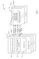
- the system 100 provides for hybrid closed and open-loop control.
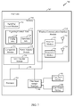
- the system 100 includes base stations 102 (N number of base stations - N being an integer), wireless terminals (or user equipment (UE)) 104 (M number of wireless terminals - M being an integer), respective power controllers 106, respective wireless terminal verifiers 108, respective verification comparators 110, and a scheduler 120.
- base stations 102 N number of base stations - N being an integer
- wireless terminals or user equipment (UE))
- M number of wireless terminals - M being an integer
- respective power controllers 106 respective wireless terminal verifiers 108
- respective verification comparators 110 respective verification comparators
- the system employs both open-loop and closed-loop controls with a load indicator to mitigate the inter-cell interference.
- the wireless terminal 104 provides for the wireless terminal 104 a control method that listens to more than one cell's load commands.
- the load commands from the neighboring cells can be conveyed via the air interface, or they can be conveyed by the serving cell through the inter eNode-B communications via the backhaul. This allows an end node to overcome a typical limitation of a serving cell not being aware of interference caused by transmission of its terminals to other cells.
- wireless terminal 104 when wireless terminal 104 starts it is controlled by base station 102 via an open-loop control function to establish target power and receiver interference levels.
- the UE when the UE enters a network or it suddenly experiences a drastic change in path loss, its transmit PSD is adjusted by an open-loop algorithm to allocate for a fast update based on download (DL) path loss.
- the open-loop algorithm controls interference level to some extent in the sense that target received signal to noise ratio (SNR) can be made a function of the path loss to a serving cell, and neighboring non-serving cells.
- SNR target received signal to noise ratio
- the UE 104 later updates its transmit PSD by listening to load indicators from neighboring non-serving cells.
- the load commands from the neighboring cells can be conveyed via the air interface, or they can be conveyed by the serving cell through the inter eNode-B communications via the backhaul.
- DOWN load commands are sent to the UE from its neighboring non-serving cells when they experience a higher interference level compared to a target - otherwise UP commands are transmitted.
- the UE 104 lowers its transmit PSD once it receives the DOWN commands; otherwise, it increases its transmit PSD.
- serving cell adjusts the Tx PSD of the UE accordingly based on the received load commands from the neighboring cells.
- the adjustment can be subsumed in the scheduling commands or it can be done by serving cell sending down the load commands to the UE. It is to be appreciated that the PSD adjustment corresponding to load commands may not be as drastic as that corresponding to open-loop control. As load indicators indicate interference level seen by other cells, tight interference control can be achieved, and thus fast and tight interference control can be obtained.
- Scheduler 120 provides for permitting scheduler flexibility in reducing inter-cell interference - the scheduler 120 for each cell has flexibility to allocate variable bandwidth and power spectral density (PSD) to end nodes in its domain.
- PSD power spectral density
- the scheduler 120 can allow higher transmit power usage for end node's in cell centers where that greater power usage does not cause interference with other cells.
- System 100 can comprise a base station 102 that receives, transmits, repeats, etc., wireless communication signals to a wireless terminal 104. Further, it is contemplated that system 100 may include a plurality of base stations similar to base station 102, such as 102n2 and 102nN, and/or a plurality of wireless terminals similar to wireless terminal 104, such as 104m2 and 104mM. It is to be appreciated that while the discussion will focus on the singular stations for clarity, aspects may involve multiple base stations and multiple wireless terminals.
- Base station 102 can comprise a transmitter chain and a receiver chain, each of which can in turn comprise a plurality of components associated with signal transmission and reception (e.g ., processors, modulators, multiplexers, demodulators, demultiplexers, antennas, etc.), as will be appreciated by one skilled in the art.
- Base station 102 may be a fixed station and/or mobile.
- Wireless terminal 104 can be, for example, a cellular phone, a smart phone, a laptop, a handheld communication device, a handheld computing device, a satellite radio, a global positioning system, a PDA, and/or any other suitable device for communicating over wireless communication system 100.
- wireless terminal 104 may be fixed or mobile.
- Wireless terminal 104 may communicate with base station 102 (and/or disparate base station(s)) on a downlink and/or an uplink channel at any given moment.
- the downlink refers to the communication link from base station 102 to wireless terminal 104
- the uplink channel refers to the communication link from wireless terminal 104 to base station 102.
- Base station 102 may further communicate with other base station(s) and/or any disparate devices (e.g ., servers) (not shown) that may perform functions such as, for example, authentication and authorization of wireless terminal 104, accounting, billing, and so on.
- Base station 102 may further include a power controller 106 and a wireless terminal verifier 108.
- Power controller 106 may measure a power level associated with wireless terminal 104 (and/or any disparate wireless terminals). Further, power controller 106 may transmit power commands to wireless terminal 104 to facilitate adjusting the power level. For instance, power controller 106 may transmit a power command in one or more transmission units associated with a first subset of transmission units. The power commands, for instance, may indicate to increase a power level, decrease a power level, remain at a power level, and the like.
- wireless terminal 104 may alter an associated power level a fixed (e.g., preset) and/or variable amount.
- the preset amounts may be of variable size based on certain factors (e.g. frequency reuse factors, channel conditions at different mobile stations).
- wireless terminal verifier 108 may transmit information as a function of a terminal identifier related to a wireless terminal (e.g ., wireless terminal 104) in one or more transmission units associated with a second subset of transmission units.
- a terminal identifier related to a wireless terminal e.g ., wireless terminal 104
- one or more ON identifiers may be assigned to each wireless terminal when in session ON state and the ON identifiers may be associated with the first subset and the second subset of transmission units.
- Transmission units may be in variable formats (e.g. time domain, frequency domain, hybrid of both time and frequency domains).
- Power controller 106 may transmit power commands over a downlink power control channel (DLPCCH).
- DLPCCH downlink power control channel
- resources may be assigned to wireless terminal 104 by base station 102 as wireless terminal 104 accesses a session ON state; such resources may include particular DLPCCH segments, one or more ON identifiers, etc.
- the DLPCCH may be utilized by a base station sector attachment point (e.g., employing power controller 106) to transmit downlink power control messages to control transmission power of wireless terminal 104.
- Wireless terminal verifier 108 may transmit information associated with a wireless terminal (e.g ., wireless terminal 104) to which the power commands correspond along with the power commands transferred by power controller 106.
- wireless terminal verifier 108 may transmit information as a function of a terminal identifier (e.g., scrambling mask) associated with the wireless terminal (e.g., wireless terminal 104).
- Wireless terminal verifier 108 may transfer such information over the DLPCCH.
- information associated with wireless terminal 104 may be transmitted over the DLPCCH with a subset of the power command transmissions from power controller 106.
- Wireless terminal 104 may further include a verification information comparator 110 that evaluates the received information associated with wireless terminal 104.
- Verification information comparator 110 may analyze the received information to determine whether wireless terminal 104 is utilizing resources as set forth by base station 102; thus, verification information comparator 110 may evaluate information included in the Q component of symbols transmitted over the DLPCCH.
- base station 102 may have assigned identifier(s) (e.g ., session ON ID) to wireless terminal 104, and verification information comparator 110 may analyze whether wireless terminal 104 employs appropriate resources associated with the assigned identifier(s).
- verification information comparator 110 may determine whether wireless terminal 104 is utilizing segments of the DLPCCH allocated by base station 102 and/or whether base station 102 has reclaimed resources (e.g., session ON ID) previously assigned to wireless terminal 104.
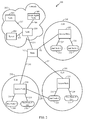
- an exemplary communication system 200 (e.g., a cellular communication network) implemented in accordance with various aspects, which comprises a plurality of nodes interconnected by communications links 205, 207, 208, 211, 230, 231, 232, 233, 234, 235, 236, 237, 238, and 239.
- Nodes in exemplary communication system 200 exchange information using signals (e.g., messages) based on communication protocols (e.g., the Internet Protocol (IP)).
- IP Internet Protocol
- the communications links of system 200 may be implemented, for example, using wires, fiber optic cables, and/or wireless communications techniques.
- Exemplary communication system 200 includes a plurality of end nodes 260, 270, 261, 271, 262, 272, which access communication system 200 via a plurality of access nodes 220, 221, and 222.
- End nodes 260, 270, 261, 271, 262, 272 may be, e.g., wireless communication devices or terminals
- access nodes 220, 221, 222 may be, e.g., wireless access routers or base stations.
- Exemplary communication system 200 also includes a number of other nodes 204, 206, 209, 210, and 212, used to provide interconnectivity or to provide specific services or functions.
- exemplary communication system 200 includes a Server 204 used to support transfer and storage of state pertaining to end nodes.
- the Server node 204 may be an AAA server, a Context Transfer Server, a server including both AAA server functionality and Context Transfer server functionality.
- Exemplary communication system 200 depicts a network 202 that includes Server 204, node 206 and a home agent node 209, which are connected to an intermediate network node 210 by corresponding network links 205, 207 and 208, respectively.
- Intermediate network node 210 in network 202 also provides interconnectivity to network nodes that are external from the perspective of network 202 via network link 211.
- Network link 211 is connected to another intermediate network node 212, which provides further connectivity to a plurality of access nodes 240, 241, 242 via network links 230, 231, 232, respectively.
- Each access node 240, 240', 240" is depicted as providing connectivity to a plurality of M end nodes (260, 270), (261, 271), (262, 272), respectively, via corresponding access links (233, 234), (235, 236), (237, 238), respectively.
- each access node 240, 241, 242 is depicted as using wireless technology (e.g ., wireless access links) to provide access.
- a radio coverage area e.g ., communications cells 250, 251, and 252) of each access node 240, 241, 242, respectively, is illustrated as a circle surrounding the corresponding access node.
- end nodes may employ access links (239) to non-serving neighbor access nodes. Uplink and Downlink data may be transferred between the end node and a number of neighboring access nodes.
- Exemplary communication system 200 is presented as a basis for the description of various aspects set forth herein. Further, various disparate network topologies are intended to fall within the scope of the claimed subject matter, where the number and type of network nodes, the number and type of access nodes, the number and type of end nodes, the number and type of Servers and other Agents, the number and type of links, and the interconnectivity between nodes may differ from that of exemplary communication system 200 depicted in Fig. 2 . Additionally, functional entities depicted in exemplary communication system 200 may be omitted or combined. Also, the location or placement of the functional entities in the network may be varied.
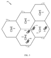
- Fig 3 illustrates an aspect of multi-cell environment.
- Cell 350 has end node 360 to end node 370 in its domain.
- Cell 351 has end node 361 to end node 371 in its domain.
- Cell 350 is portrayed as having neighbor cells 351, 352 and 354.
- Cell 351 is portrayed as having neighbor cells 350, 352 and 353.
- Cell 353 is not a neighbor of Cell 350.
- Each cell has a base station that is predominantly controlling the end nodes in its cell.
- the base station's scheduler 120 has the flexibility to allocate variable bandwidth and PSD to the end nodes in its domain.
- End node 360 may be permitted to operate with a higher PSD than end node 370.
- the variability is desired to increase cell throughput and allow greater bandwidth and higher PSD to end nodes closer to the center of the cell (e.g. 360). If end node 370 were to transmit at a higher PSD, it would run the risk of creating interference for end node 371, which is located in neighboring cell 351.
- Fig 4 illustrates an aspect of inter-cell interference.
- End node 471 is stationary and near the edge of service cell 451.
- End node 461 also in cell 451 operates at an independent power and/or bandwidth than end node 471.
- end node 470 is traveling through an urban canyon 480 with an increased PSD (e.g. a higher PSD than end node 460).
- End node 470 travels out of the canyon on path 490 turning in the direction of end node 471.
- the sudden exit from the urban canyon conditions and proximity to end node 471 causes a sharp rise in interference for end nodes 470 and 471 and a resulting large change in path loss function.
- the path loss function is not solely tied to a serving cell, but is also a function of path loss from an end node to neighbor serving cells.
- the path loss with neighbor cell 452 has no effect.
- end node 471 has had no change in its PSD or commands from its own serving cell 451.
- base station 440 would be unaware of its interference caused to end node 471.
- An aspect allows open loop control to quickly mitigate the inter-cell interference and transition to a closed loop control at an appropriate time.
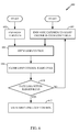
- Fig 5 illustrates a management logic flow chart.
- the target Rxed SNR is established. This target is made a function of the path loss both from the end node to the serving node as well as the end node to the neighbor cell nodes.
- the end node may be as represented as item 700, Figure 7 .
- Open loop control 504 is initially used by the access node, as may be represented in Figure 8 , item 800.
- Open-loop power control has been widely used in the conventional wireless systems. The principle of the open-loop is to compensate for [a fraction of] the serving cell path loss so that a certain target SNR can be maintained from the long-term perspective.
- stand-alone open-loop approach does not take inter-cell interference into account. Meanwhile it also suffers from measurement errors.
- Load indicator is an effective way to control the inter-cell interference, however some extreme scenarios such as in urban canyon, an end node may turn around the corner and suddenly blast its power in another cell, traditional load commands may not be able to control the interference down to the target level fast enough.
- End node's transmit PSD is adjusted based on open-loop algorithm to allocate for a fast update based on the DL path loss.
- the open-loop algorithm may set different target Rxed SNR for different end nodes.
- the open-loop algorithm controls the interference level to some extent in the sense that the target Rxed SNR has been made as a function the path loss to the serving cell and neighboring non-serving cells.
- the novel aspect of including a path loss reading from non-serving cells is called inter-cell PC.
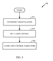
- Fig 6 illustrates a management logic flow chart. From the end node's perspective, management begins when the User Equipment (UE) is turned on 602. At 602, the target Rxed SNR is established. This target is made a function of the path loss both from the end node to the serving node as well as the end node to the neighbor cell nodes. Entry into the cycle may also happen 604 when the end node experiences a drastic change in its path loss reading (e.g. when bombarded with interference from another end unit emerging from an urban canyon as presented in Figure 4 ).
- UE User Equipment
- Open loop control 606 is initially used by the access node, as may be represented in Figure 8 , item 800.
- Open-loop power control has been widely used in the conventional wireless systems. The principle of the open-loop is to compensate for [a fraction of] the serving cell path loss so that a certain target SNR can be maintained from the long-term perspective.
- stand-alone open-loop approach does not take inter-cell interference into account. Meanwhile it also suffers from measurement errors.
- Load indicator is an effective way to control the inter-cell interference, however some extreme scenarios such as in urban canyon, an end node may turn around the corner and suddenly blast its power in another cell, traditional load commands may not be able to control the interference down to the target level fast enough.
- End node's transmit PSD is adjusted based on open-loop algorithm to allocate for a fast update based on the DL path loss.
- the open-loop algorithm may set different target Rxed SNR for different end nodes.
- the end node loop control changes to closed loop control 608.
- These levels may be held in the appropriate memory stores as in item 710 Figure 7 and item 810 Figure 8 .
- the end node updates its transmit PSD by listening to the load indicators from the serving cell and at least one other neighboring non-serving cell which generates the highest level of interference.
- the method of how the end node obtains the other cell load indicators may be variable (e.g. the end node can obtain through internode B or direct listening to other cells).
- the proposed closed loop PSD control algorithm incorporates the action that each cell broadcasts an uplink load indicator (busy or not) in the downlink in a periodic manner as may be indicated through items 824 and 834 Figure 8 , and each end node decodes the load indicator bits, as may be indicated by item 712 Figure 7 , from at least one dominant interfering cell (based on path loss measurements), and the end node appropriately reduces, holds or increase its allowed Tx power spectral density based on the serving cell and nonserving neighboring cells through an exemplary device such as item 748 in Figure 7 .
- the serving cell adjusts the Tx PSD of the UE based on the received load commands from the neighboring cells.
- the adjustment can be subsumed in the scheduling commands or it can be done by serving cell sending down the load commands to the UE.
- the UE monitors its path loss function 610.
- the closed loop control remains in effect while the path loss function remains within a threshold level 612. If the path loss function falls out of the threshold target band 604, the control method reverts to open loop control 606.
- the closed loop protocol includes a reference PSD that is maintained at the serving cell (Node-B) and is used for intra cell power control.
- This reference PSD is based on a periodic known signal such as CQI.
- the end node periodically reports a PSD delta and a supportable bandwidth.
- the reference PSD delta is a function of load indication commands from non-serving cells and indicates the power headroom available at the end node assuming that the assigned (granted) bandwidth for data transmission equals the CQI bandwidth.
- the supportable bandwidth is computed from the maximum transmit power and the Tx PSD and indicates the maximum bandwidth that may be supported by the end node, given the max Tx power constraint and the PSD at which end node transmits data.
- the serving node then grants an uplink assignment consisting of bandwidth (e.g.
- the end node transmits the packet in accordance with the assignment with the PSD delta.
- Inter-cell power control is performed in part by the end node listening to load indication commands from the strongest interfering cell.
- load indications may be generated by comparing the filtered IoT with the target operating point and transmitted once every 10ms using OOK.
- the up/down step size to adjust the PSD offset may be variable.
- the PSD adjustment corresponding to load commands in closed loop power control may not be as drastic as that corresponding to open-loop.
- load indicators indicate the interference level seen by other cells a tight interference control can be achieved. Therefore, with the proposed approach a fast and tight interference control can be obtained.
- the initial PSD setting is crucial for system performance.
- This initial PSD setting is typically set by the access node without full knowledge of the variability of a number of factors. These factors vary per end node and include factors outside of the control of the end node.
- Fig. 7 illustrates an exemplary end node 700 (e.g., a mobile node, a wireless terminal) associated with various aspects.
- Exemplary end node 700 may be an apparatus that may be used as any one of the end nodes 260, 270, 261, 271, 262, 272 depicted in Fig. 2 .
- end node 700 includes a processor 704, a wireless communication interface 730, a user input/output interface 740 and memory 710 coupled together by a bus 706.
- various components of end node 700 can exchange information, signals and data via bus 706.
- Components 704, 706, 710, 730, 740 of end node 700 may be located inside a housing 702.
- Wireless communication interface 730 provides a mechanism by which the internal components of the end node 700 can send and receive signals to/from external devices and network nodes (e.g., access nodes).
- Wireless communication interface 730 includes, for example, a receiver module 732 with a corresponding receiving antenna 736 and a transmitter module 734 with a corresponding transmitting antenna 738 used for coupling end node 700 to other network nodes ( e.g., via wireless communications channels).
- Exemplary end node 700 also includes a user input device 742 (e.g., keypad) and a user output device 744 (e.g., display), which are coupled to bus 706 via user input/output interface 740.
- user input device 742 and user output device 744 can exchange information, signals and data with other components of end node 700 via user input/output interface 740 and bus 706.
- User input/output interface 740 and associated devices e.g ., user input device 742, user output device 744
- user input device 742 and user output device 744 provide functionality that allows a user to control end node 700 and applications (e.g ., modules, programs, routines, functions, etc.) that execute in memory 710 of end node 700.
- Processor 704 may be under control of various modules (e.g ., routines) included in memory 710 and may control operation of end node 700 to perform various signaling and processing as described herein.
- the modules included in memory 710 are executed on startup or as called by other modules. Modules may exchange data, information, and signals when executed. Modules may also share data and information when executed.
- Memory 710 of end node 700 may include a signaling/control module 712 and signaling/control data 714.
- Signaling/control module 712 controls processing relating to receiving and sending signals (e.g ., messages) for management of state information storage, retrieval, and processing.
- Signaling/control data 714 includes state information such as, for instance, parameters, status, and/or other information relating to operation of the end node.
- signaling/control data 714 may include configuration information 716 (e.g., end node identification information) and operational information 718 (e.g., information about current processing state, status of pending responses, etc.).
- Signaling/control module 712 may access and/or modify signaling/control data 714 (e.g ., update configuration information 716 and/or operational information 718).
- Memory 710 of end node 700 may also include a comparator module 746, a power adjuster module 748, and/or an error handler module 750. Although not depicted, it is to be appreciated that comparator module 746, power adjuster module 748, and/or error handler module 750 may store and/or retrieve data associated therewith that may be stored in memory 710. Comparator module 746 may evaluate received information associated with end node 700 and effectuate a comparison with expected information.
- Fig. 8 provides an illustration of an exemplary access node 800 implemented in accordance with various aspects described herein.
- Exemplary access node 800 may be an apparatus utilized as any one of access nodes 240, 241, 242 depicted in Fig. 2 .
- Access node 800 may include a processor 804, memory 810, a network/internetwork interface 820 and a wireless communication interface 830, coupled together by a bus 806. Accordingly, various components of access node 800 can exchange information, signals and data via bus 806.
- the components 804, 806, 810, 820, 830 of the access node 800 may be located inside a housing 802.
- Network/internetwork interface 820 provides a mechanism by which the internal components of access node 800 can send and receive signals to/from external devices and network nodes.
- Network/internetwork interface 820 includes a receiver module 822 and a transmitter module 824 used for coupling access node 800 to other network nodes ( e.g., via copper wires or fiber optic lines).
- Wireless communication interface 830 also provides a mechanism by which the internal components of access node 800 can send and receive signals to/from external devices and network nodes (e.g., end nodes).
- Wireless communication interface 830 includes, for instance, a receiver module 832 with a corresponding receiving antenna 836 and a transmitter module 834 with a corresponding transmitting antenna 838.
- Wireless communication interface 830 may be used for coupling access node 800 to other network nodes ( e.g., via wireless communication channels).
- Processor 804 may be under control of various modules (e.g ., routines) included in memory 810 and may control operation of access node 800 to perform various signaling and processing.
- the modules included in memory 810 may be executed on startup or as called by other modules that may be present in memory 810. Modules may exchange data, information, and signals when executed. Modules may also share data and information when executed.
- memory 810 of access node 800 may include a State Management module 812 and a Signaling/Control module 814. Corresponding to each of these modules, memory 810 also includes State Management data 813 and the Signaling/Control data 815.
- State Management Module 812 controls the processing of received signals from end nodes or other network nodes regarding state storage and retrieval.
- State Management Data 813 includes, for instance, end-node related information such as the state or part of the state, or the location of the current end node state if stored in some other network node.
- State Management module 812 may access and/or modify State Management data 813.
- Signaling/Control module 814 controls the processing of signals to/from end nodes over wireless communication interface 830 and to/from other network nodes over network/internetwork interface 820 as necessary for other operations such as basic wireless function, network management, etc.
- Signaling/Control data 815 includes, for example, end-node related data regarding wireless channel assignment for basic operation, and other network-related data such as the address of support/management servers, configuration information for basic network communications.
- Signaling/Control module 814 may access and/or modify Signaling/Control data 815.
- Memory 810 may additionally include a unique identification (ID) assigner module 840, an ON identification (ID) assigner module 842, a power controller module 844, and/or a wireless terminal (WT) verifier module 846.
- unique ID assigner module 840, ON ID assigner module 842, power controller module 844, and/or WT verifier module 846 may store and/or retrieve associated data retained in memory 810. Further, unique ID assigner module 840 may allocate a terminal identifier (e.g., scrambling mask) to a wireless terminal.
- ON ID assigner module 842 may assign an ON identifier to a wireless terminal while the wireless terminal is in session ON state.
- Power controller module 844 may transmit power control information to a wireless terminal or to other access nodes.
- WT verifier module 846 may enable including wireless terminal related information in a transmission unit.
- Fig 9 illustrates a system 900 in accordance with an aspect.
- Component 902 establishes a target Rxed which is a function of the path loss both from the end node to the serving node as well as the end node to the neighbor cell nodes.
- the end node may be as represented as item 700, Figure 7 .
- Open loop control 504 is initially used by the access node, as may be represented in Figure 8 , item 800.
- End node's transmit PSD is adjusted based on open-loop algorithm to allocate for a fast update based on the DL path loss.
- the open-loop algorithm may set different target Rxed SNR for different end nodes.
- closed loop control replaces open loop control.
- Component 904 utilizes open loop control, and component 906 switches to using closed loop control.
- Inter-cell power control is done by the UE listening to load indication commands from the strongest interfering cell.
- Load indications are generated by comparing the filtered IoT with the target operating point and transmitted once every 10ms using OOK.
- the up/down step size to adjust the PSD offset is 0.05dB with scenarios D1, D2 and D4 and it is 0.5dB with D3.
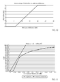
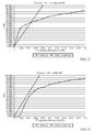
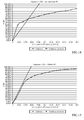
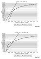
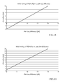
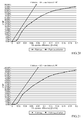
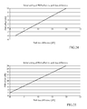
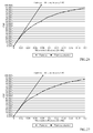
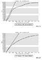
- Tables 1 and 2 we show the system performance in terms of mean operating IoT, average cell throughput and the 5% edge UE throughput with and without inter-cell power control. Fairness plots for different link budgets are shown in Figures 11 to 17 , respectively. The fairness is defined as the CDF of the UE spectral efficiency.
- Table 1 System throughput with inter-cell power control Link Budget Site-to-site Distance (m) Speed (kph) Mean IoT (dB) Spectral Efficiency (b/s/Hz) 5% Spectral Efficiency (b/s/Hz) D1 500 3 4.43 0.69 0.017 D2 500 30 4.41 0. 71 0.017 D3 1732 3 4.40 0.57 0.004 D4 1000 3 4.44 0.68 0.017
- Table 2 System throughput without inter-cell power control - same initial PSD setting Link Budget Site-to-site Distance (m) Speed (kph) Mean IoT (dB) Spectral Efficiency (b/s/Hz) 5% Spectral Efficiency (b/s/Hz) D1 500 3 2.94 0.81 0.002 D2 500 30 3.01 0. 82 0.002 D3 1732 3 N/A N/A D4 1000 3 2.97 0.81 0.002
- Table 3 System throughput without inter-cell power control - modified initial PSD setting I Link Budget Site-to-site Distance (m) Speed (kph) Mean IoT (dB) Spectral Efficiency (b/s/Hz) 5% Spectral Efficiency (b/s/Hz) D1 500 3 5.76 0.75 0.017 D2 500 30 5.97 0.81 0.017 D3 1732 3 3.48 0.51 0.005 D4 1000 3 5.68 0.75 0.017 Table 4: System throughput without inter-cell power control - modified initial PSD setting II Link Budget Site-to-site Distance (m) Speed (kph) Mean IoT (dB) Spectral Efficiency (b/s/Hz) 5% Spectral Efficiency (b/s/Hz) D1 500 3 4.53 0.77 0.004 D2 500 30 4.47 0.82 0.004 D3 1732 3 3.95 0.56 0.005 D4 1000 3 4.46 0.78 0.004
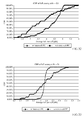
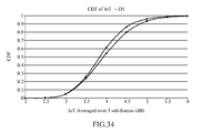
- short-term IoT can be evaluated with and without inter-cell power control.
- Figure 34 we provide the CDF of short-term IoT when there is and there is not inter-cell power control.
- the short-term IoT is defined as the IoT averaged over 1.5ms. It can be seen that without inter-cell power control the IoT overshoot is higher.
- the techniques described herein may be implemented with modules (e.g., procedures, functions, and so on) that perform the functions described herein.
- the software codes may be stored in memory units and executed by processors.
- the memory unit may be implemented within the processor or external to the processor, in which case it can be communicatively coupled to the processor via various means as is known in the art.
Landscapes
- Engineering & Computer Science (AREA)
- Computer Networks & Wireless Communication (AREA)
- Signal Processing (AREA)
- Mobile Radio Communication Systems (AREA)
Claims (13)
- Procédé facilitant le contrôle des interférences entre cellules dans un système OFDM comprenant :l'établissement d'un SNR cible reçu qui est une fonction des pertes de trajet à la fois depuis un noeud terminal vers une cellule de desserte et depuis le noeud terminal vers des cellules de non-desserte voisines ;l'utilisation d'une commande de densité spectrale de puissance, PSD, en boucle ouverte au départ de l'utilisation du noeud terminal ou lorsque la fonction de perte de trajet du noeud terminal dépasse un niveau de seuil ;la commutation sur la commande de PSD en boucle fermée une fois que les étapes précédentes ont été effectuées ;le retour à la commande de PSD en boucle ouverte lorsque la fonction de perte de trajet du noeud dépasse le niveau de seuil.
- Procédé selon la revendication 1, où la commande de PSD en boucle ouverte utilise des instructions d'indication de charge provenant de cellules voisines de non-desserte.
- Procédé selon la revendication 1, où la commande de PSD en boucle fermée utilise des instructions d'indication de charge provenant de cellules voisines de non-desserte.
- Procédé selon la revendication 1, dans lequel chaque cellule diffuse une indication de charge en liaison montante dans une liaison descendante de manière périodique ou chaque cellule envoie les instructions de charge à ses cellules voisines via le réseau de retour.
- Procédé selon la revendication 1, comprenant le décodage de bits indicateurs de charge sur la base de la mesure de perte de trajet depuis au moins une cellule interférente dominante ou la prise en compte des instructions de charge envoyées depuis la cellule de desserte qui peuvent être incorporées au message de programmation ou renvoyées de manière explicite.
- Procédé selon la revendication 5, comprenant le fait d'amener le noeud terminal à réduire la densité spectrale de puissance, PSD, de transmission.
- Procédé selon la revendication 1, comprenant le maintien d'une PSD de référence d'au moins un noeud de desserte et l'utilisation de la PSD de référence pour une commande de puissance intracellulaire.
- Procédé selon la revendication 1, comprenant la réception d'une valeur de delta de PSD et de données de bande passante supportables depuis un noeud terminal qui est un équipement utilisateur, UE.
- Procédé selon la revendication 7, où l'au moins un noeud de desserte offrant une affectation en liaison montante comprend des informations de bande passante et un format de paquets.
- Procédé selon la revendication 1, comprenant l'affectation d'une bande passante aux noeuds terminaux qui sont des équipements utilisateur, UEs, sur la base de l'équation suivante :

 Φréf(i) = PSD de référence pour UE iWréf = bande passante de référenceΦtx(i) = PSD Tx pour UE iΔpsd = amplification de PSD de référence (dB)Wtx(i) = bande passante supportable pour UE idans lequel :
la PSD de référence est définie par :


- Support lisible par ordinateur sur lequel sont stockées des instructions exécutables par ordinateur pour effectuer le procédé selon l'une quelconque des revendications 1 à 10.
- Processeur qui exécute un code pour contrôler les interférences entre cellules dans un système OFDM et exécute un code exécutable sur ordinateur stocké sur un support de stockage pour effectuer le procédé selon l'une quelconque des revendications 1 à 10.
- Système qui facilite le contrôle des interférences entre cellules dans un système OFDM, comprenant :des moyens (902) d'établissement d'un SNR cible reçu qui est fonction des pertes de trajet à la fois depuis un noeud terminal vers une cellule de desserte et depuis un noeud terminal vers des cellules voisines de non-desserte ;des moyens (904) d'utilisation d'une commande de densité spectrale de puissance PSD en boucle ouverte au départ de l'utilisation d'un noeud terminal ou lorsque la fonction de perte de trajet du noeud terminal dépasse un niveau de seuil ;des moyens (906) de commutation vers la commande de PSD en boucle fermée après une commande de PSD en boucle ouverte initiale et d'établissement du SNR cible reçu ; etdans lequel le système est aménagé pour revenir à la commande de PSD en boucle ouverte lorsque la fonction de perte de trajet du noeud dépasse le niveau de seuil.
Applications Claiming Priority (2)
| Application Number | Priority Date | Filing Date | Title |
|---|---|---|---|
| US86392806P | 2006-11-01 | 2006-11-01 | |
| PCT/US2007/083260 WO2008055247A1 (fr) | 2006-11-01 | 2007-10-31 | Commande de puissance entre des cellules pour la gestion de brouillage |
Publications (2)
| Publication Number | Publication Date |
|---|---|
| EP2092662A1 EP2092662A1 (fr) | 2009-08-26 |
| EP2092662B1 true EP2092662B1 (fr) | 2016-09-28 |
Family
ID=38991314
Family Applications (1)
| Application Number | Title | Priority Date | Filing Date |
|---|---|---|---|
| EP07844791.9A Active EP2092662B1 (fr) | 2006-11-01 | 2007-10-31 | Commande de puissance entre des cellules pour la gestion de brouillage |
Country Status (10)
| Country | Link |
|---|---|
| US (1) | US8285216B2 (fr) |
| EP (1) | EP2092662B1 (fr) |
| JP (1) | JP5323712B2 (fr) |
| KR (1) | KR101086604B1 (fr) |
| CN (1) | CN101536349B (fr) |
| BR (1) | BRPI0717886A2 (fr) |
| CA (1) | CA2666215A1 (fr) |
| RU (1) | RU2414058C2 (fr) |
| TW (1) | TW200838202A (fr) |
| WO (1) | WO2008055247A1 (fr) |
Families Citing this family (43)
| Publication number | Priority date | Publication date | Assignee | Title |
|---|---|---|---|---|
| US8190163B2 (en) * | 2002-08-08 | 2012-05-29 | Qualcomm Incorporated | Methods and apparatus of enhanced coding in multi-user communication systems |
| US7363039B2 (en) | 2002-08-08 | 2008-04-22 | Qualcomm Incorporated | Method of creating and utilizing diversity in multiple carrier communication system |
| US6961595B2 (en) * | 2002-08-08 | 2005-11-01 | Flarion Technologies, Inc. | Methods and apparatus for operating mobile nodes in multiple states |
| US7411895B2 (en) * | 2003-02-19 | 2008-08-12 | Qualcomm Incorporated | Controlled superposition coding in multi-user communication systems |
| US8593932B2 (en) * | 2003-05-16 | 2013-11-26 | Qualcomm Incorporated | Efficient signal transmission methods and apparatus using a shared transmission resource |
| US7925291B2 (en) * | 2003-08-13 | 2011-04-12 | Qualcomm Incorporated | User specific downlink power control channel Q-bit |
| US20080045259A1 (en) * | 2006-08-15 | 2008-02-21 | Zukang Shen | Cellular Uplink Power Control with Inter-NodeB Power Control Information Exchange |
| JP2010516208A (ja) | 2007-01-11 | 2010-05-13 | クゥアルコム・インコーポレイテッド | 無線通信システムにおいてdtxおよびdrxを使用すること |
| US9295003B2 (en) * | 2007-03-19 | 2016-03-22 | Apple Inc. | Resource allocation in a communication system |
| US8457676B2 (en) * | 2007-06-20 | 2013-06-04 | Nokia Siemens Networks Oy | Power headroom reporting method |
| US8577304B2 (en) * | 2007-10-31 | 2013-11-05 | Icera, Inc. | Synchronous CDMA communication system |
| US8165098B2 (en) * | 2008-02-11 | 2012-04-24 | Mitsubishi Electric Research Laboratories, Inc. | Method for allocating resources in cell-edge bands of OFDMA networks |
| US8548383B2 (en) | 2008-08-27 | 2013-10-01 | Qualcomm Incorporated | Power spectrum density control for wireless communications |
| KR101571563B1 (ko) * | 2008-09-24 | 2015-11-25 | 엘지전자 주식회사 | 다중셀 협력 무선통신시스템에서의 상향링크 전력의 제어 방법 및 이를 지원하는 단말 |
| US8982750B2 (en) * | 2009-01-16 | 2015-03-17 | Qualcomm Incorporated | Method and apparatus for transmitting overload indicator over the air |
| DE602009001185D1 (de) * | 2009-02-26 | 2011-06-09 | Alcatel Lucent | Optischer OFDM-Transponder mit Leistungsverwaltung |
| KR101530201B1 (ko) | 2009-03-03 | 2015-06-19 | 삼성전자주식회사 | 간섭 제어 방법 또는/및 전송 전력 제어 방법을 적용하여 신호를 전송하는 신호 전송 시스템 및 그 방법 |
| WO2011004947A1 (fr) * | 2009-07-10 | 2011-01-13 | Lg Electronics Inc. | Procédé d'optimisation d'une zone comp pour un mode de traitement conjoint |
| US8976729B2 (en) * | 2009-08-19 | 2015-03-10 | Qualcomm Incorporated | Maximum power spectral density reporting in response to overload indications |
| US8559325B2 (en) * | 2009-09-15 | 2013-10-15 | Qualcomm Incorporated | Systems and methods for over the air load indicator for wireless scheduling |
| WO2011042043A1 (fr) * | 2009-10-05 | 2011-04-14 | Nokia Siemens Networks Oy | Régulation des parasites |
| US9113420B2 (en) * | 2009-12-29 | 2015-08-18 | Telefonaktiebolaget L M Ericsson (Publ) | Radio system |
| US8868091B2 (en) | 2010-01-18 | 2014-10-21 | Qualcomm Incorporated | Methods and apparatus for facilitating inter-cell interference coordination via over the air load indicator and relative narrowband transmit power |
| KR101593238B1 (ko) * | 2010-01-20 | 2016-02-12 | 삼성전자주식회사 | 무선 통신 시스템에서 송신 전력 제어 장치 및 방법 |
| CN102792732A (zh) * | 2010-01-22 | 2012-11-21 | 诺基亚公司 | 用于多小区设备到设备干扰控制的蜂窝控制侦听 |
| CN102149111B (zh) * | 2010-02-08 | 2015-09-16 | 中兴通讯股份有限公司 | 一种邻区信息管理方法及系统 |
| US8571482B2 (en) * | 2010-09-11 | 2013-10-29 | Nokia Corporation | Dynamic autonomous resource allocation and channel access in cellular System Uplink |
| CN102573028A (zh) * | 2010-12-16 | 2012-07-11 | 中兴通讯股份有限公司 | 一种开环功率控制方法及系统 |
| EP2687051A1 (fr) * | 2011-03-17 | 2014-01-22 | Nokia Solutions and Networks Oy | Procédé et appareil de détermination de puissance d'émission |
| CN103493559B (zh) * | 2011-04-13 | 2017-03-15 | Lg电子株式会社 | 在无线通信系统中发送和接收用于减轻小区间干扰的信号的方法及其装置 |
| EP2719228A4 (fr) * | 2011-06-08 | 2014-11-05 | Nokia Solutions & Networks Oy | Puissance d'émission |
| US8848698B2 (en) * | 2011-10-22 | 2014-09-30 | Lg Electronics Inc. | Scheduling method in multiple access system and apparatus using the same |
| RU2608755C1 (ru) * | 2013-04-25 | 2017-01-24 | Интел Корпорейшн | Устройство связи миллиметрового диапазона длин волн и способ интеллектуального управления мощностью передачи и плотностью потока мощности |
| KR20150047801A (ko) * | 2013-10-25 | 2015-05-06 | 삼성전자주식회사 | 무선 통신 시스템에서 트래픽 오프로드 방법 및 장치 |
| CN105981451A (zh) | 2013-12-16 | 2016-09-28 | 瑞典爱立信有限公司 | 用于无线电通信网络中的上行链路和/或下行链路功率控制的方法和设备 |
| CN104837190B (zh) * | 2014-02-07 | 2018-09-14 | 中国电信股份有限公司 | 用于实现自适应开环功率控制的方法和装置 |
| US9673887B1 (en) * | 2014-03-21 | 2017-06-06 | Rockwell Collins, Inc. | Self-calibration of a communications device for transmit power level control |
| EP3141048B1 (fr) * | 2014-05-06 | 2018-08-01 | Telefonaktiebolaget LM Ericsson (publ) | Commande de puissance en liaison montante dans des réseaux hétérogènes |
| DE102015110160B4 (de) * | 2015-06-24 | 2018-03-29 | Intel IP Corporation | Mehrfachsendefähiges Datensendesystem und Verfahren zu dessen Betreiben |
| WO2019126948A1 (fr) * | 2017-12-25 | 2019-07-04 | 华为技术有限公司 | Procédé d'ajustement de paramètre et appareil associé |
| WO2019158123A1 (fr) * | 2018-02-16 | 2019-08-22 | Telefonaktiebolaget Lm Ericsson (Publ) | Procédé et système de transmission en liaison montante ordonnancée permettant de résoudre une interférence de canal dans un réseau sans fil à l'aide d'un indicateur de coordination |
| US11057882B1 (en) * | 2018-04-03 | 2021-07-06 | T-Mobile Innovations Llc | Systems and methods for dynamically setting frame configuration in a wireless network |
| US11582699B2 (en) | 2021-02-15 | 2023-02-14 | Harris Global Communications, Inc. | Mobile ad hoc network providing power control and associated methods |
Family Cites Families (17)
| Publication number | Priority date | Publication date | Assignee | Title |
|---|---|---|---|---|
| JPH1065604A (ja) * | 1996-08-23 | 1998-03-06 | Sony Corp | 通信方法、基地局及び端末装置 |
| US6377809B1 (en) | 1997-09-16 | 2002-04-23 | Qualcomm Incorporated | Channel structure for communication systems |
| JP2000151500A (ja) * | 1998-11-05 | 2000-05-30 | Nec Saitama Ltd | Cdma送信電力制御方法及びそのシステム |
| US6628956B2 (en) * | 1999-03-15 | 2003-09-30 | Telefonaktiebolaget Lm Ericsson (Publ) | Adaptive power control in a radio communications systems |
| JP3360053B2 (ja) * | 1999-11-19 | 2002-12-24 | 埼玉日本電気株式会社 | 移動通信端末 |
| US6707862B1 (en) * | 2000-03-21 | 2004-03-16 | Denso Corporation | Predictive data rate control in wireless transmitters |
| US6600772B1 (en) * | 2000-03-21 | 2003-07-29 | Interdigital Communications Corporation | Combined closed loop/open loop power control in a time division duplex communication system |
| JP3456197B2 (ja) | 2000-08-30 | 2003-10-14 | 日本電気株式会社 | 送信電力格納制御回路及びその方法 |
| US6587697B2 (en) * | 2001-05-14 | 2003-07-01 | Interdigital Technology Corporation | Common control channel uplink power control for adaptive modulation and coding techniques |
| JP4256158B2 (ja) | 2002-12-26 | 2009-04-22 | パナソニック株式会社 | 無線通信装置及び無線通信方法 |
| US7979078B2 (en) * | 2003-06-16 | 2011-07-12 | Qualcomm Incorporated | Apparatus, system, and method for managing reverse link communication resources in a distributed communication system |
| JP4107432B2 (ja) | 2004-03-03 | 2008-06-25 | 独立行政法人電子航法研究所 | 移動局及び移動局側通信制御方法及び基地局及び基地局通信制御方法及び通信システム |
| US8452316B2 (en) * | 2004-06-18 | 2013-05-28 | Qualcomm Incorporated | Power control for a wireless communication system utilizing orthogonal multiplexing |
| DE602004022932D1 (de) | 2004-07-13 | 2009-10-15 | Alcatel Lucent | Verfahren zur endgeräteunterstützen Interferenzkontrolle in einem Mehrträger-Mobilkommunikationssystem |
| KR100725773B1 (ko) * | 2004-08-20 | 2007-06-08 | 삼성전자주식회사 | 시분할 듀플렉스 방식의 이동통신 시스템에서 단말기의상태에 따라 상향링크 전력제어방식을 적응적으로변경하기 위한 장치 및 방법 |
| US7205842B2 (en) * | 2005-01-13 | 2007-04-17 | Telefonaktiebolaget Lm Ericsson (Publ) | Continuous alternating closed-open loop power control |
| RU2369965C2 (ru) | 2005-03-15 | 2009-10-10 | Квэлкомм Инкорпорейтед | Информация о помехах из множества секторов для управления мощностью |
-
2007
- 2007-10-31 US US12/443,969 patent/US8285216B2/en active Active
- 2007-10-31 BR BRPI0717886-7A patent/BRPI0717886A2/pt not_active IP Right Cessation
- 2007-10-31 EP EP07844791.9A patent/EP2092662B1/fr active Active
- 2007-10-31 JP JP2009535456A patent/JP5323712B2/ja not_active Expired - Fee Related
- 2007-10-31 WO PCT/US2007/083260 patent/WO2008055247A1/fr not_active Ceased
- 2007-10-31 CA CA002666215A patent/CA2666215A1/fr not_active Abandoned
- 2007-10-31 CN CN2007800406475A patent/CN101536349B/zh active Active
- 2007-10-31 KR KR1020097010948A patent/KR101086604B1/ko active Active
- 2007-10-31 RU RU2009120508/09A patent/RU2414058C2/ru active
- 2007-11-01 TW TW096141263A patent/TW200838202A/zh unknown
Also Published As
| Publication number | Publication date |
|---|---|
| WO2008055247A1 (fr) | 2008-05-08 |
| US20100029212A1 (en) | 2010-02-04 |
| RU2414058C2 (ru) | 2011-03-10 |
| KR20090075876A (ko) | 2009-07-09 |
| RU2009120508A (ru) | 2010-12-10 |
| EP2092662A1 (fr) | 2009-08-26 |
| CN101536349A (zh) | 2009-09-16 |
| TW200838202A (en) | 2008-09-16 |
| CN101536349B (zh) | 2013-02-13 |
| JP2010508787A (ja) | 2010-03-18 |
| BRPI0717886A2 (pt) | 2013-11-05 |
| JP5323712B2 (ja) | 2013-10-23 |
| US8285216B2 (en) | 2012-10-09 |
| CA2666215A1 (fr) | 2008-05-08 |
| KR101086604B1 (ko) | 2011-11-23 |
Similar Documents
| Publication | Publication Date | Title |
|---|---|---|
| EP2092662B1 (fr) | Commande de puissance entre des cellules pour la gestion de brouillage | |
| US11743832B2 (en) | Uplink power control for power limited terminals | |
| US8116800B2 (en) | Reverse link traffic power control for LBC FDD | |
| US8428521B2 (en) | Control for uplink in MIMO communication system | |
| RU2408137C1 (ru) | Широковещательная передача информации о помехах в обслуживающем секторе и соответствующее управление мощностью трафика в обратной линии связи | |
| CN101361288B (zh) | 使用多速率干扰指示的功率控制 | |
| US20130109432A1 (en) | Techniques to control uplink power | |
| KR101411245B1 (ko) | 업링크 전력 제어 기법 | |
| JP5630906B2 (ja) | 無線通信システムにおける送信電力制御装置及び方法 | |
| JP5089754B2 (ja) | 移動通信システム、基地局及び送信電力制御方法 | |
| Muhammad et al. | Uplink closed loop power control for LTE system | |
| EP3075195B1 (fr) | Noeud de réseau et procédé de détermination de puissance d'émission en liaison descendante pour un canal partagé de liaison descendante | |
| HK1162834A (en) | Reverse link traffic power control for lbc fdd | |
| HK1126905A (en) | Power control using multiple rate interference indications | |
| HK1093613A (en) | Radio base station apparatus and transmission power control method in a radio base station |
Legal Events
| Date | Code | Title | Description |
|---|---|---|---|
| PUAI | Public reference made under article 153(3) epc to a published international application that has entered the european phase |
Free format text: ORIGINAL CODE: 0009012 |
|
| 17P | Request for examination filed |
Effective date: 20090529 |
|
| AK | Designated contracting states |
Kind code of ref document: A1 Designated state(s): AT BE BG CH CY CZ DE DK EE ES FI FR GB GR HU IE IS IT LI LT LU LV MC MT NL PL PT RO SE SI SK TR |
|
| DAX | Request for extension of the european patent (deleted) | ||
| 17Q | First examination report despatched |
Effective date: 20100714 |
|
| REG | Reference to a national code |
Ref country code: DE Ref legal event code: R079 Ref document number: 602007048128 Country of ref document: DE Free format text: PREVIOUS MAIN CLASS: H04B0007005000 Ipc: H04W0052080000 |
|
| GRAP | Despatch of communication of intention to grant a patent |
Free format text: ORIGINAL CODE: EPIDOSNIGR1 |
|
| RIC1 | Information provided on ipc code assigned before grant |
Ipc: H04W 52/08 20090101AFI20160404BHEP Ipc: H04W 52/10 20090101ALI20160404BHEP Ipc: H04W 52/24 20090101ALI20160404BHEP |
|
| INTG | Intention to grant announced |
Effective date: 20160419 |
|
| GRAS | Grant fee paid |
Free format text: ORIGINAL CODE: EPIDOSNIGR3 |
|
| GRAA | (expected) grant |
Free format text: ORIGINAL CODE: 0009210 |
|
| AK | Designated contracting states |
Kind code of ref document: B1 Designated state(s): AT BE BG CH CY CZ DE DK EE ES FI FR GB GR HU IE IS IT LI LT LU LV MC MT NL PL PT RO SE SI SK TR |
|
| REG | Reference to a national code |
Ref country code: GB Ref legal event code: FG4D |
|
| REG | Reference to a national code |
Ref country code: CH Ref legal event code: EP |
|
| REG | Reference to a national code |
Ref country code: AT Ref legal event code: REF Ref document number: 833697 Country of ref document: AT Kind code of ref document: T Effective date: 20161015 |
|
| REG | Reference to a national code |
Ref country code: FR Ref legal event code: PLFP Year of fee payment: 10 |
|
| REG | Reference to a national code |
Ref country code: IE Ref legal event code: FG4D |
|
| REG | Reference to a national code |
Ref country code: DE Ref legal event code: R096 Ref document number: 602007048128 Country of ref document: DE |
|
| REG | Reference to a national code |
Ref country code: LT Ref legal event code: MG4D |
|
| PG25 | Lapsed in a contracting state [announced via postgrant information from national office to epo] |
Ref country code: FI Free format text: LAPSE BECAUSE OF FAILURE TO SUBMIT A TRANSLATION OF THE DESCRIPTION OR TO PAY THE FEE WITHIN THE PRESCRIBED TIME-LIMIT Effective date: 20160928 Ref country code: LT Free format text: LAPSE BECAUSE OF FAILURE TO SUBMIT A TRANSLATION OF THE DESCRIPTION OR TO PAY THE FEE WITHIN THE PRESCRIBED TIME-LIMIT Effective date: 20160928 |
|
| REG | Reference to a national code |
Ref country code: NL Ref legal event code: MP Effective date: 20160928 |
|
| REG | Reference to a national code |
Ref country code: AT Ref legal event code: MK05 Ref document number: 833697 Country of ref document: AT Kind code of ref document: T Effective date: 20160928 |
|
| PG25 | Lapsed in a contracting state [announced via postgrant information from national office to epo] |
Ref country code: LV Free format text: LAPSE BECAUSE OF FAILURE TO SUBMIT A TRANSLATION OF THE DESCRIPTION OR TO PAY THE FEE WITHIN THE PRESCRIBED TIME-LIMIT Effective date: 20160928 Ref country code: GR Free format text: LAPSE BECAUSE OF FAILURE TO SUBMIT A TRANSLATION OF THE DESCRIPTION OR TO PAY THE FEE WITHIN THE PRESCRIBED TIME-LIMIT Effective date: 20161229 Ref country code: NL Free format text: LAPSE BECAUSE OF FAILURE TO SUBMIT A TRANSLATION OF THE DESCRIPTION OR TO PAY THE FEE WITHIN THE PRESCRIBED TIME-LIMIT Effective date: 20160928 Ref country code: SE Free format text: LAPSE BECAUSE OF FAILURE TO SUBMIT A TRANSLATION OF THE DESCRIPTION OR TO PAY THE FEE WITHIN THE PRESCRIBED TIME-LIMIT Effective date: 20160928 Ref country code: BE Free format text: LAPSE BECAUSE OF NON-PAYMENT OF DUE FEES Effective date: 20161031 |
|
| PG25 | Lapsed in a contracting state [announced via postgrant information from national office to epo] |
Ref country code: EE Free format text: LAPSE BECAUSE OF FAILURE TO SUBMIT A TRANSLATION OF THE DESCRIPTION OR TO PAY THE FEE WITHIN THE PRESCRIBED TIME-LIMIT Effective date: 20160928 Ref country code: RO Free format text: LAPSE BECAUSE OF FAILURE TO SUBMIT A TRANSLATION OF THE DESCRIPTION OR TO PAY THE FEE WITHIN THE PRESCRIBED TIME-LIMIT Effective date: 20160928 |
|
| PG25 | Lapsed in a contracting state [announced via postgrant information from national office to epo] |
Ref country code: CZ Free format text: LAPSE BECAUSE OF FAILURE TO SUBMIT A TRANSLATION OF THE DESCRIPTION OR TO PAY THE FEE WITHIN THE PRESCRIBED TIME-LIMIT Effective date: 20160928 Ref country code: IS Free format text: LAPSE BECAUSE OF FAILURE TO SUBMIT A TRANSLATION OF THE DESCRIPTION OR TO PAY THE FEE WITHIN THE PRESCRIBED TIME-LIMIT Effective date: 20170128 Ref country code: AT Free format text: LAPSE BECAUSE OF FAILURE TO SUBMIT A TRANSLATION OF THE DESCRIPTION OR TO PAY THE FEE WITHIN THE PRESCRIBED TIME-LIMIT Effective date: 20160928 Ref country code: SK Free format text: LAPSE BECAUSE OF FAILURE TO SUBMIT A TRANSLATION OF THE DESCRIPTION OR TO PAY THE FEE WITHIN THE PRESCRIBED TIME-LIMIT Effective date: 20160928 Ref country code: BE Free format text: LAPSE BECAUSE OF FAILURE TO SUBMIT A TRANSLATION OF THE DESCRIPTION OR TO PAY THE FEE WITHIN THE PRESCRIBED TIME-LIMIT Effective date: 20160928 Ref country code: ES Free format text: LAPSE BECAUSE OF FAILURE TO SUBMIT A TRANSLATION OF THE DESCRIPTION OR TO PAY THE FEE WITHIN THE PRESCRIBED TIME-LIMIT Effective date: 20160928 Ref country code: PL Free format text: LAPSE BECAUSE OF FAILURE TO SUBMIT A TRANSLATION OF THE DESCRIPTION OR TO PAY THE FEE WITHIN THE PRESCRIBED TIME-LIMIT Effective date: 20160928 Ref country code: BG Free format text: LAPSE BECAUSE OF FAILURE TO SUBMIT A TRANSLATION OF THE DESCRIPTION OR TO PAY THE FEE WITHIN THE PRESCRIBED TIME-LIMIT Effective date: 20161228 Ref country code: PT Free format text: LAPSE BECAUSE OF FAILURE TO SUBMIT A TRANSLATION OF THE DESCRIPTION OR TO PAY THE FEE WITHIN THE PRESCRIBED TIME-LIMIT Effective date: 20170130 |
|
| REG | Reference to a national code |
Ref country code: CH Ref legal event code: PL |
|
| REG | Reference to a national code |
Ref country code: DE Ref legal event code: R097 Ref document number: 602007048128 Country of ref document: DE |
|
| PG25 | Lapsed in a contracting state [announced via postgrant information from national office to epo] |
Ref country code: IT Free format text: LAPSE BECAUSE OF FAILURE TO SUBMIT A TRANSLATION OF THE DESCRIPTION OR TO PAY THE FEE WITHIN THE PRESCRIBED TIME-LIMIT Effective date: 20160928 |
|
| REG | Reference to a national code |
Ref country code: IE Ref legal event code: MM4A |
|
| PG25 | Lapsed in a contracting state [announced via postgrant information from national office to epo] |
Ref country code: DK Free format text: LAPSE BECAUSE OF FAILURE TO SUBMIT A TRANSLATION OF THE DESCRIPTION OR TO PAY THE FEE WITHIN THE PRESCRIBED TIME-LIMIT Effective date: 20160928 Ref country code: LI Free format text: LAPSE BECAUSE OF NON-PAYMENT OF DUE FEES Effective date: 20161031 Ref country code: CH Free format text: LAPSE BECAUSE OF NON-PAYMENT OF DUE FEES Effective date: 20161031 |
|
| PLBE | No opposition filed within time limit |
Free format text: ORIGINAL CODE: 0009261 |
|
| STAA | Information on the status of an ep patent application or granted ep patent |
Free format text: STATUS: NO OPPOSITION FILED WITHIN TIME LIMIT |
|
| PG25 | Lapsed in a contracting state [announced via postgrant information from national office to epo] |
Ref country code: LU Free format text: LAPSE BECAUSE OF NON-PAYMENT OF DUE FEES Effective date: 20161031 |
|
| 26N | No opposition filed |
Effective date: 20170629 |
|
| REG | Reference to a national code |
Ref country code: FR Ref legal event code: PLFP Year of fee payment: 11 |
|
| PG25 | Lapsed in a contracting state [announced via postgrant information from national office to epo] |
Ref country code: SI Free format text: LAPSE BECAUSE OF FAILURE TO SUBMIT A TRANSLATION OF THE DESCRIPTION OR TO PAY THE FEE WITHIN THE PRESCRIBED TIME-LIMIT Effective date: 20160928 Ref country code: IE Free format text: LAPSE BECAUSE OF NON-PAYMENT OF DUE FEES Effective date: 20161031 |
|
| PG25 | Lapsed in a contracting state [announced via postgrant information from national office to epo] |
Ref country code: HU Free format text: LAPSE BECAUSE OF FAILURE TO SUBMIT A TRANSLATION OF THE DESCRIPTION OR TO PAY THE FEE WITHIN THE PRESCRIBED TIME-LIMIT; INVALID AB INITIO Effective date: 20071031 Ref country code: CY Free format text: LAPSE BECAUSE OF FAILURE TO SUBMIT A TRANSLATION OF THE DESCRIPTION OR TO PAY THE FEE WITHIN THE PRESCRIBED TIME-LIMIT Effective date: 20160928 |
|
| PG25 | Lapsed in a contracting state [announced via postgrant information from national office to epo] |
Ref country code: MT Free format text: LAPSE BECAUSE OF NON-PAYMENT OF DUE FEES Effective date: 20161031 Ref country code: MC Free format text: LAPSE BECAUSE OF FAILURE TO SUBMIT A TRANSLATION OF THE DESCRIPTION OR TO PAY THE FEE WITHIN THE PRESCRIBED TIME-LIMIT Effective date: 20160928 Ref country code: TR Free format text: LAPSE BECAUSE OF FAILURE TO SUBMIT A TRANSLATION OF THE DESCRIPTION OR TO PAY THE FEE WITHIN THE PRESCRIBED TIME-LIMIT Effective date: 20160928 |
|
| REG | Reference to a national code |
Ref country code: FR Ref legal event code: PLFP Year of fee payment: 12 |
|
| PGFP | Annual fee paid to national office [announced via postgrant information from national office to epo] |
Ref country code: GB Payment date: 20240912 Year of fee payment: 18 |
|
| PGFP | Annual fee paid to national office [announced via postgrant information from national office to epo] |
Ref country code: FR Payment date: 20240913 Year of fee payment: 18 |
|
| PGFP | Annual fee paid to national office [announced via postgrant information from national office to epo] |
Ref country code: DE Payment date: 20240913 Year of fee payment: 18 |