EP2092830A1 - Einheit zur Rückgewinnung von Salz in Schinkenverarbeitungslinien - Google Patents
Einheit zur Rückgewinnung von Salz in Schinkenverarbeitungslinien Download PDFInfo
- Publication number
- EP2092830A1 EP2092830A1 EP09152515A EP09152515A EP2092830A1 EP 2092830 A1 EP2092830 A1 EP 2092830A1 EP 09152515 A EP09152515 A EP 09152515A EP 09152515 A EP09152515 A EP 09152515A EP 2092830 A1 EP2092830 A1 EP 2092830A1
- Authority
- EP
- European Patent Office
- Prior art keywords
- tube
- unit
- air
- arms
- container
- Prior art date
- Legal status (The legal status is an assumption and is not a legal conclusion. Google has not performed a legal analysis and makes no representation as to the accuracy of the status listed.)
- Withdrawn
Links
- 150000003839 salts Chemical class 0.000 title claims abstract description 40
- 230000001788 irregular Effects 0.000 claims abstract description 6
- 238000009938 salting Methods 0.000 claims description 8
- XLYOFNOQVPJJNP-UHFFFAOYSA-N water Substances O XLYOFNOQVPJJNP-UHFFFAOYSA-N 0.000 claims description 4
- 238000001035 drying Methods 0.000 claims description 2
- 239000007787 solid Substances 0.000 description 6
- 230000000694 effects Effects 0.000 description 5
- 235000013372 meat Nutrition 0.000 description 4
- 239000002245 particle Substances 0.000 description 4
- 238000004140 cleaning Methods 0.000 description 3
- 238000004891 communication Methods 0.000 description 3
- 238000007664 blowing Methods 0.000 description 2
- 230000001680 brushing effect Effects 0.000 description 2
- 238000001914 filtration Methods 0.000 description 2
- 235000013305 food Nutrition 0.000 description 2
- 238000007689 inspection Methods 0.000 description 2
- 238000000926 separation method Methods 0.000 description 2
- 229910001220 stainless steel Inorganic materials 0.000 description 2
- 239000010935 stainless steel Substances 0.000 description 2
- 101100117236 Drosophila melanogaster speck gene Proteins 0.000 description 1
- 241000334993 Parma Species 0.000 description 1
- 230000001464 adherent effect Effects 0.000 description 1
- 239000012267 brine Substances 0.000 description 1
- 230000006835 compression Effects 0.000 description 1
- 238000007906 compression Methods 0.000 description 1
- 230000018044 dehydration Effects 0.000 description 1
- 238000006297 dehydration reaction Methods 0.000 description 1
- 230000001419 dependent effect Effects 0.000 description 1
- 238000010586 diagram Methods 0.000 description 1
- 230000001747 exhibiting effect Effects 0.000 description 1
- 235000011194 food seasoning agent Nutrition 0.000 description 1
- 230000005484 gravity Effects 0.000 description 1
- 235000015143 herbs and spices Nutrition 0.000 description 1
- 239000007788 liquid Substances 0.000 description 1
- 239000000463 material Substances 0.000 description 1
- 239000000203 mixture Substances 0.000 description 1
- 230000004048 modification Effects 0.000 description 1
- 238000012986 modification Methods 0.000 description 1
- 210000000056 organ Anatomy 0.000 description 1
- 235000015277 pork Nutrition 0.000 description 1
- 238000002360 preparation method Methods 0.000 description 1
- 238000011084 recovery Methods 0.000 description 1
- 238000007493 shaping process Methods 0.000 description 1
- HPALAKNZSZLMCH-UHFFFAOYSA-M sodium;chloride;hydrate Chemical compound O.[Na+].[Cl-] HPALAKNZSZLMCH-UHFFFAOYSA-M 0.000 description 1
- 239000000243 solution Substances 0.000 description 1
- 238000005406 washing Methods 0.000 description 1
Images



Classifications
-
- A—HUMAN NECESSITIES
- A22—BUTCHERING; MEAT TREATMENT; PROCESSING POULTRY OR FISH
- A22C—PROCESSING MEAT, POULTRY, OR FISH
- A22C17/00—Other devices for processing meat or bones
- A22C17/08—Cleaning, e.g. washing, meat or sausages
Definitions
- the invention relates to a unit for recovering salt in ham working lines.
- the present invention relates to an equipment for removing salt distributed on the surface of food products, typically seasoned salt meats, among which Parma ham and Speck, and recuperating the salt.
- preparation of hams includes a stage of salting, in which the fresh leg of pork is treated with a mixture of salt and herbs and spices, both dry and moist, which serves to give taste to the meat and to ensure correct dehydration thereof, before the seasoning stage.
- the salt can be simply poured onto the meat to be treat, or can be applied by brushing with special rubber brushes.
- mechanised plants which comprise a linear transporter which advances the hams, and one or more operating stations, for pouring on the salt and possibly for brushing the units as they advance on the conveyor.
- the product After the salting operation the product is kept at a suitable temperature in a cold store for a certain amount of time.
- the excess salt which is generally damp, is removed by blowing compressed air through a suitable shaped nozzle.
- the salt thus removed falls on the conveyor, and from there to the floor, or inside the machines.
- the removal of the salt from the surface of the hams can also be done by aspirating the salt directly from the surface of the ham or other sacked meat.
- An aim of the present invention is to make available a unit for removing salt from hams by blowing and for recovering and re-using the salt removed from the hams, and in general for cleaning ham-salting lines.
- a further aim of the invention is to make available a unit for removing excess salt from the surface of the hams and also for recovering the salt.
- a further aim of the invnention is to make available a unit which exhibits great versatiliaty and is able to function excellently independently of the irregular shape of the hams and similar food products to which it is applied, while at the same time guaranteeing recovery of the removed salt.
- a further aim of the main invention is to make available an equipment for for recovering and re-using the salt removed from the hams, and in general for cleaning the ham-salting machines.
- a further aim of the invention is to achieve the mentioned objectives with a solution that is simple, rational and relatively inexpensive.
- the characteristics of the invention which comprises a unit provided with a line of tubes along which are inserted, in series, a pneumatic machine, such as a compressor or a ventilator, destined to create a forced air current which runs along the line of tubes from an aspirating mouth towards an outlet mouth.
- a pneumatic machine such as a compressor or a ventilator
- the unit comprises a separator device, positioned between the compressor and the aspirating mouth, which is destined to separate and collect the solid bodies, such as salt, which are transported in it,from the air current, and to make the salt available for possible re-use.
- At least an air filter is preferably inserted on the tube line, which air filter is located in series between the separator device and the compressor, such as to prevent the compressor from getting clogged by grains of salt or other solid particles which might escape from the separator device.
- the separator device preferably comprises a rigid container, having, for example, a cylindrical geometry of revolution with respect to the central axis thereof, which container is provided with an intake duct for directing the air current entering tangentially against the internal walls of the container, and an axial exit duct for enabling air to be expelled in an axial direction.
- the separator device is in practice a cyclone in which a swirling motion is impressed on the air current, such as to dissipate the kinetic energy of the heaviest solid particles, which fall by force of gravity towards the bottom of the container, while the air exits axially, entrained by the depression created by the pneumatic machine located downstream.
- the cyclone comprises a transversal separator wall which, internally of the container, separates a lower first chamber from an upper second chamber into which the intake duct opens.
- the transversal separator wall is fixed and comprises a circumferential series of deviator blades, which are all inclined in a same direction, such as to deviate the air passing from the upper second chamber to the lower first chamber in a tangential direction.
- the deviator blades accelerate the swirl of air internally of the container, thus more efficiently performing the centrifugal separation of the salt grains, which accumulate on the bottom of the lower chamber.
- the separator device further comprises an extension tube of the outlet duct, which develops axially internally of the container, for a limited tract before the intake duct mouth, such as to obstruct direct outflow of the air introduced via the duct.
- the extension tube preferably crosses the upper second chamber of the container, and opens internally of the lower first chamber, entering in a central opening of the transversal separator wall.
- the invention has the aspiration mouth of the pneumatic machine located in connection, by means of a flexible tube of an appropriate length, with an aspiration nozzle, while the outlet mouth is placed in communication by a flexible tube of a convenient length, with an ejector nozzle.
- an aspirating device is connected to the aspiration mouth of the pneumatic machine, which aspirating device goes into contact with the ham, and is provided with a plurality of aspirating nozzles located the the end of respective side-by-side oscillating arms, the arms being mobile independently of one another such as to adapt to the irregular surface of the hams.
- the aims of the invention are attained by a plant having the characteristics stated in the independent claim.
- the equipment 1 comprises a support trolley 2, which is provided with wheels 20 such as to be able to move over the floor when pushed or drawn manually by a user, and also comprises a handle 21.
- a line of tubes is mounted on the support trolley 2, which line of tubes 3 guides an air current which runs from an intake mouth 30 towards an ejector nozzle 31.
- a compressor 4 for generating an air current
- a separator device denoted in its entirety by 5 which is interposed between the compressor 4 and the intake mouth 30, and is for separating the solid bodies transported in the air flow from the flow itself.
- the compressor 4 is a blade-type compressor and thus comprises an electric motor which rotates an impeller inserted along the tube line 3.
- the compressor 4 is preferably of such a size as to be able to generate a maximum pressure difference of not less than 200 mbar.
- centrifuge compressor 4 can be substituted by a pneumatic machine of any other known type having the same characteristics.
- the intake mouth 30 is located at an end of a length-adjustable rigid rod 32, which is connected to the separator device 5 by a flexible duct 33, making it easier to handle for the user.
- the ejector nozzle 31 is located at an end of a rigid lance 34, which is connected to the compressor 4 by means of a flexible conduit 35, such as also to be easier to handle.
- the separator device 5 and the compressor 4 are connected by rigid tubes, along which two air filters are mounted in series, a first filter 6 being for retaining the larger solid particles escaping from the separator device 5 and a second filter 7, interposed between the first filter 6 and the compressor 4 being for retaining the smaller particles that might not be captured by the filter 6.
- the first filter 6 is provided with an inspection device 60 (see figure 2 ) and is equipped with a steel-mesh filtering cartridge which can easily be dismounted and cleaned every time the inspection device 60 signals that the filter is blocked.
- the second filter 7 is equipped with a paper filtering cartridge.
- the separator device 5 comprises a rigid external container 50 having a geometry of revolution about a central axis of symmetry which in the present example is cylindrical.
- the container 50 is mounted in a vertical position, and is located above an opening from which an underlying service chamber is accessible, where a removable recipient 9 is housed, typically a bag, for collecting the solid bodies which have been separated from the air current.
- the container 50 is provided with an intake duct 51, communicating with the intake mouth 30, which opens on the lateral cylindrical wall of the container 50, the mouth 30 being oriented in a tangential direction of the container 50, and the mouth 30 also being slightly inclined in an axial direction.
- the intake duct 51 is destined to direct the entering air current tangentially against the internal walls of the container 50, such as to create internally of the container 50 a swirling motion which develops from above in a downwards direction according to a predetermined rotation direction, which in the present example is clockwise as seen in plan view.
- the container 50 is closed on the bottom by a tilting hatch 52, while it is closed at the top by a fixed lid 53, on which an outlet duct 54 is afforded that communicates with the compressor 4, which outlet duct 54 enables air to exit in an axial direction.
- the container 50 is closed at the bottom by an automatically-activated star valve 52 ( figure 12 ) which exhibits a volume divided into four sectors which are arranged at 90°, and a rotating organ 52' which enables the salt which accumulates at the bottom of the separator device 2 to be conveyed to the chute opening 52", without putting the inside of the device in communication with the outside.
- an automatically-activated star valve 52 figure 12
- a rotating organ 52' which enables the salt which accumulates at the bottom of the separator device 2 to be conveyed to the chute opening 52", without putting the inside of the device in communication with the outside.
- the outlet duct 54 extends in the form of a coaxial tube 55 which is fixed to the fixed lid 53, and which develops coaxially internally of the container 50 for a limited tract thereof, without reaching the bottom thereof.
- the coaxial tube 55 has a smaller diameter than that of the external container 50, and is located substantially in front of the mouth of the intake duct 51, such as to obstruct direct outflow of the air.
- the container 50 is about 1500 mm high and has a diameter of between 300 and 400 mm, while the coaxial tube 55 is about half as high and has a diameter which is about a quarter thereof, i.e. comprised between 75 and 100 mm.
- the internal volume of the container 50 is sub-divided by a transversal wall 56 into two distinct chambers, of which one is an upper chamber 57, into which an inlet duct 51 opens, and a lower chamber 58, into which the coaxial tube 55 opens.
- the upper chamber 57 is completely crossed by the coaxial tube 55, which thus gives it the shape of an annular space.
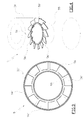
- the transversal wall 56 is substantially ring-shaped, having an external diameter which is substantially equal to the internal diameter of the container 50, and an internal diameter which is substantially equal to the external diameter of the coaxial tube 55, on which the wall 56 is inserted and stably fixed.
- the transversal wall 56 comprises a circumferential series of deviator blades 56', which are all inclined successively in the same direction along the circumference.
- the deviator blades 56' are inclined from above in a downwards direction and in a clockwise direction, i.e. in a same direction as the rotation direction of the swirl of air internally of the container 50.
- the blades 56' accelerate the air swirl in a tangential direction which air swirl passes axially from the upper annular chamber 57 to the lower chamber 58, facilitating the centrifugal separation of the salt.
- the blades 56' are preferably fashioned in a single body with the separator wall 56, by cutting and shaping of identical circumferential limbs which are singly bent along a fold line which is radial with respect to the axis of the ring.
- the separator device 5 also comprises a hose 8 for dispensing a jet of water internally of the container 50, such as to facilitate washing thereof.
- the hose 8 opens from the upper lid 53 and is intercepted by an opening and closing tap valve 80 for adjusting the water flow.
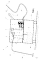
- Figure 5 shows the apparatus 10 of the invention, which can comprise a support carriage 2 which is provided with wheels 20, and moves on the floor such as to be arranged straddling a line with a conveyor belt 220 which supplies the hams 210, the line being provided with an entrance for the salted product and an exit for the de-salted product.
- the apparatus 10 can be mounted permanently on the ham supply line.
- the second embodiment also comprises a line of tubes 33, 35 which guides an air current flowing from the aspiration group 4, which is described in greater detail herein below and which aspirates the salt from the surface of the hams 21, to an air ejector device 600.
- the aspiration group 100 is connected to the separator device 2 via the flexible tube 33.
- the line of tubes 35 can optionally be mounted on the support carriage, which line of tubes 35 guides the air current generated by the pneumatic machine 4 which flows from the aspiration group 1 towards an ejector nozzle 600, the function of which is to blow finishing air onto the de-salted hams.
- the aspiration group 100 exhibits a central tube 400, which is preferably made of stainless steel and provided with a plurality of slots 430, the slots 430 being arranged side by side on at least part of the surface of the central tube 400 ( figure 6 ).
- An intermediate tube 420 preferably made of plastic material, is connected to the central tube 400, and also exhibits a plurality of slots 440 which are arranged side by side on at least a part of the surface of the intermediate tube 420, and which, in cooperation with the slots 430 of the central tube 400, define passages for the aspirated air (figures from 8 to 10).
- a plurality of arms 450 is inserted on the intermediate tube 420 in a stacked arrangement, reaching up as far as the wider-section hose 410 ( figure 11 ).
- the arms are internally holed (at the point denoted by reference numeral 470) and provided with a terminal nozzle 48, the nozzles 480 being arranged in such quantity that they cover the width of the ham conveyor line.
- the arms 450 are preferably made of stainless steel, each arm exhibiting a holed ring 460 which can be inserted over the intermediate tube 420 in such a way that the hole 470 of the holed ring 420 cooperates with the slots 440 of the intermediate tube 42 to define passages for the aspirated air.
- each of the arms 450 exhibits a substantially straight first portion 450', and an angled second portion 450" which curves in the direction of the ham to be treated and terminates with a respective nozzle 480.
- Each arm 450 is supported by the tubes 400 and 410, which are arranged in a substantially horizontal position, each arm 45 being independently rotatable with respect to the others and, thanks to the shape of the slots 430 and 440, being at all times able to provide an aspiration channel.
- the aspiration group 100 when positioned above a ham 210 advancing on the supply line, can follow the irregular form of the ham 210 with each of its arms 450, since the arms rotate under the effect of their own weight with respect to the horizontal, their nozzles 480 substantially never detaching themselves from the salted surface of the ham, thus providing optimal aspiration of the salt.
- the central tube 400 and the intermediate tube 410 can be made to rotate one with respect to the other in such a way as to partialise the air flow affecting the slots 430 and 440.
- the separator device 2 comprises a hose 8, which provides a water jet inside the container 50, in such a way as to facilitate the cleaning thereof.
- the conduit 35 which is connected to the output tube of the compressor 4, supplies a manifold 610 with compressed air, from which manifold 610 one or more oscillating outlets 620 emerge, which rest on the ham in transit under the effect of their own weight.
- the outlets 620 direct an air jet on the ham in order to remove any residual salt and any liquids having residues of brine which eluded the action of the aspiration nozzles 100.
- First of all the pneumatic machine 4 is activated in order to generate a forced air current which flows along the line of tubes of the apparatus.
- the air current creates an aspiration effect at the aspiration group 100.
- the aspiration group 100 effectively aspirates the salt from the surface of the hams 210, since the individual arms 450 are independently capable of following the irregular surface of the hams 210 during the aspiration operation, remaining adherent to the surface of the ham 210 under the effect of their own weight.
- the aspirated salt is then drawn by the air current into the separator device 5, which functions as a usual cyclone.
- the star valve 520 of the container 50 is automatically activated to allow the salt to be discharged without however setting the cyclone in communication with the outside, thus enabling the apparatus to function continuously.
Landscapes
- Life Sciences & Earth Sciences (AREA)
- Engineering & Computer Science (AREA)
- Wood Science & Technology (AREA)
- Zoology (AREA)
- Food Science & Technology (AREA)
- Meat, Egg Or Seafood Products (AREA)
Applications Claiming Priority (2)
| Application Number | Priority Date | Filing Date | Title |
|---|---|---|---|
| ITRE20080023 ITRE20080023A1 (it) | 2008-02-20 | 2008-02-20 | '' attrezzatura per la pulizia di macchine per la salatura dei prosciutti '' |
| ITRE2008A000115A IT1392234B1 (it) | 2008-12-03 | 2008-12-03 | Attrezzatura per la rimozione di sale dai prosciutti |
Publications (1)
| Publication Number | Publication Date |
|---|---|
| EP2092830A1 true EP2092830A1 (de) | 2009-08-26 |
Family
ID=40592031
Family Applications (1)
| Application Number | Title | Priority Date | Filing Date |
|---|---|---|---|
| EP09152515A Withdrawn EP2092830A1 (de) | 2008-02-20 | 2009-02-11 | Einheit zur Rückgewinnung von Salz in Schinkenverarbeitungslinien |
Country Status (1)
| Country | Link |
|---|---|
| EP (1) | EP2092830A1 (de) |
Cited By (2)
| Publication number | Priority date | Publication date | Assignee | Title |
|---|---|---|---|---|
| FR3008580A1 (fr) * | 2013-07-18 | 2015-01-23 | Fabrice Sayous | Procede et dispositif de conditionnement d'un jambon sec |
| ITUB20160087A1 (it) * | 2016-01-19 | 2017-07-19 | Colussi Ermes S R L | Sistema e procedimento per recuperare letti di stagionatura di materiali incoerenti, quali per esempio letti di sale per stagionare prosciutti crudi. |
Citations (5)
| Publication number | Priority date | Publication date | Assignee | Title |
|---|---|---|---|---|
| US2744792A (en) * | 1952-03-07 | 1956-05-08 | William H Mead | Apparatus for conveying comminuted materials |
| US3265445A (en) | 1964-01-20 | 1966-08-09 | Du Pont | Conveyor conduit |
| GB2293993A (en) * | 1994-09-30 | 1996-04-17 | John B Mckeown | Hydrocyclone separator |
| WO1997037746A1 (en) * | 1996-04-08 | 1997-10-16 | K-Tron Technologies, Inc. | Separator for removing fine particulates from air |
| EP1780154A1 (de) * | 2005-11-01 | 2007-05-02 | Sun Chemical B.V. | Verfahren und Vorrichtung zur Vakuumförderung von Schüttgut |
-
2009
- 2009-02-11 EP EP09152515A patent/EP2092830A1/de not_active Withdrawn
Patent Citations (5)
| Publication number | Priority date | Publication date | Assignee | Title |
|---|---|---|---|---|
| US2744792A (en) * | 1952-03-07 | 1956-05-08 | William H Mead | Apparatus for conveying comminuted materials |
| US3265445A (en) | 1964-01-20 | 1966-08-09 | Du Pont | Conveyor conduit |
| GB2293993A (en) * | 1994-09-30 | 1996-04-17 | John B Mckeown | Hydrocyclone separator |
| WO1997037746A1 (en) * | 1996-04-08 | 1997-10-16 | K-Tron Technologies, Inc. | Separator for removing fine particulates from air |
| EP1780154A1 (de) * | 2005-11-01 | 2007-05-02 | Sun Chemical B.V. | Verfahren und Vorrichtung zur Vakuumförderung von Schüttgut |
Cited By (2)
| Publication number | Priority date | Publication date | Assignee | Title |
|---|---|---|---|---|
| FR3008580A1 (fr) * | 2013-07-18 | 2015-01-23 | Fabrice Sayous | Procede et dispositif de conditionnement d'un jambon sec |
| ITUB20160087A1 (it) * | 2016-01-19 | 2017-07-19 | Colussi Ermes S R L | Sistema e procedimento per recuperare letti di stagionatura di materiali incoerenti, quali per esempio letti di sale per stagionare prosciutti crudi. |
Similar Documents
| Publication | Publication Date | Title |
|---|---|---|
| KR102318010B1 (ko) | 원심 분리와 필터를 이용한 집진장치 | |
| US9687767B2 (en) | Filter apparatus for extracting fine dust from air | |
| EP2092830A1 (de) | Einheit zur Rückgewinnung von Salz in Schinkenverarbeitungslinien | |
| KR20160149814A (ko) | 공압에 의해 운반되는 고형물을 공기로부터 분리하여 배출하는 장치 | |
| US11219241B2 (en) | Bead feeding method and bead feeding unit | |
| EP2964036A1 (de) | Verfahren und vorrichtung zur rückgewinnung von tabak aus zigaretten mit filter | |
| US20020020461A1 (en) | Powder supply system | |
| KR20170124557A (ko) | 분쇄 음식물 쓰레기 분리용 분리기 | |
| CN109122798B (zh) | 一种便于清洗的家禽宰杀装置 | |
| GB2367484A (en) | Vacuum cleaner with two-stage separation | |
| EP0566517A1 (de) | Gerät zum Säubern der Filterträger einer Kaffeemaschine | |
| US8110234B2 (en) | Mechanical deboning of poultry | |
| CN109483611A (zh) | 一种带烘干装置的金钗石斛切片机 | |
| CN212348270U (zh) | 用于压缩气体的干燥机及压缩机设备 | |
| JP6557813B2 (ja) | ニンニク鱗茎の皮剥ぎ装置 | |
| CN106457119B (zh) | 用于从空气流中高效分离颗粒的设备和方法 | |
| KR20220022185A (ko) | 생선 골육분리장치 | |
| CN115024351A (zh) | 一种扇贝壳肉分离装置 | |
| CN209379425U (zh) | 一种大米加工用碎米处理装置 | |
| CN208258910U (zh) | 一种冷摊机 | |
| RU2137382C1 (ru) | Способ обработки мяса животных и птицы и установка для его осуществления | |
| JP3970586B2 (ja) | 加工食品用異物除去装置 | |
| CN219898615U (zh) | 一种用于液熏系统的雾化喷雾装置 | |
| CN120306353B (zh) | 一种热熔胶铝罐生产用清洗装置 | |
| CN206284328U (zh) | 一种花椒剥皮机 |
Legal Events
| Date | Code | Title | Description |
|---|---|---|---|
| PUAI | Public reference made under article 153(3) epc to a published international application that has entered the european phase |
Free format text: ORIGINAL CODE: 0009012 |
|
| AK | Designated contracting states |
Kind code of ref document: A1 Designated state(s): AT BE BG CH CY CZ DE DK EE ES FI FR GB GR HR HU IE IS IT LI LT LU LV MC MK MT NL NO PL PT RO SE SI SK TR |
|
| AX | Request for extension of the european patent |
Extension state: AL BA RS |
|
| 17P | Request for examination filed |
Effective date: 20100219 |
|
| AKX | Designation fees paid |
Designated state(s): ES FR IT |
|
| REG | Reference to a national code |
Ref country code: DE Ref legal event code: 8566 |
|
| 17Q | First examination report despatched |
Effective date: 20130522 |
|
| STAA | Information on the status of an ep patent application or granted ep patent |
Free format text: STATUS: THE APPLICATION IS DEEMED TO BE WITHDRAWN |
|
| 18D | Application deemed to be withdrawn |
Effective date: 20130903 |