EP2092859A1 - Beleuchtungsverfahren und Vorrichtung für Kältegerät - Google Patents
Beleuchtungsverfahren und Vorrichtung für Kältegerät Download PDFInfo
- Publication number
- EP2092859A1 EP2092859A1 EP08425102A EP08425102A EP2092859A1 EP 2092859 A1 EP2092859 A1 EP 2092859A1 EP 08425102 A EP08425102 A EP 08425102A EP 08425102 A EP08425102 A EP 08425102A EP 2092859 A1 EP2092859 A1 EP 2092859A1
- Authority
- EP
- European Patent Office
- Prior art keywords
- lighting
- plane
- opening
- elements
- lighting elements
- Prior art date
- Legal status (The legal status is an assumption and is not a legal conclusion. Google has not performed a legal analysis and makes no representation as to the accuracy of the status listed.)
- Withdrawn
Links
- 238000000034 method Methods 0.000 title claims description 16
- 230000003287 optical effect Effects 0.000 claims abstract description 79
- 230000010355 oscillation Effects 0.000 claims description 14
- 239000007787 solid Substances 0.000 claims description 4
- 238000005286 illumination Methods 0.000 description 18
- 229910052754 neon Inorganic materials 0.000 description 13
- GKAOGPIIYCISHV-UHFFFAOYSA-N neon atom Chemical compound [Ne] GKAOGPIIYCISHV-UHFFFAOYSA-N 0.000 description 13
- 238000010586 diagram Methods 0.000 description 8
- 230000000694 effects Effects 0.000 description 6
- 230000007423 decrease Effects 0.000 description 5
- 230000008901 benefit Effects 0.000 description 4
- 238000010276 construction Methods 0.000 description 3
- 238000009792 diffusion process Methods 0.000 description 3
- 239000000463 material Substances 0.000 description 3
- 238000005516 engineering process Methods 0.000 description 2
- 238000009413 insulation Methods 0.000 description 2
- 230000008092 positive effect Effects 0.000 description 2
- 239000004065 semiconductor Substances 0.000 description 2
- 230000004888 barrier function Effects 0.000 description 1
- 238000009833 condensation Methods 0.000 description 1
- 230000001747 exhibiting effect Effects 0.000 description 1
- 230000002349 favourable effect Effects 0.000 description 1
- 230000004907 flux Effects 0.000 description 1
- 238000009434 installation Methods 0.000 description 1
- 230000010354 integration Effects 0.000 description 1
- 230000008569 process Effects 0.000 description 1
- 230000005855 radiation Effects 0.000 description 1
- 238000009420 retrofitting Methods 0.000 description 1
- 238000003466 welding Methods 0.000 description 1
Images





Classifications
-
- A—HUMAN NECESSITIES
- A47—FURNITURE; DOMESTIC ARTICLES OR APPLIANCES; COFFEE MILLS; SPICE MILLS; SUCTION CLEANERS IN GENERAL
- A47F—SPECIAL FURNITURE, FITTINGS, OR ACCESSORIES FOR SHOPS, STOREHOUSES, BARS, RESTAURANTS OR THE LIKE; PAYING COUNTERS
- A47F3/00—Show cases or show cabinets
- A47F3/001—Devices for lighting, humidifying, heating, ventilation
-
- A—HUMAN NECESSITIES
- A47—FURNITURE; DOMESTIC ARTICLES OR APPLIANCES; COFFEE MILLS; SPICE MILLS; SUCTION CLEANERS IN GENERAL
- A47F—SPECIAL FURNITURE, FITTINGS, OR ACCESSORIES FOR SHOPS, STOREHOUSES, BARS, RESTAURANTS OR THE LIKE; PAYING COUNTERS
- A47F3/00—Show cases or show cabinets
- A47F3/04—Show cases or show cabinets air-conditioned, refrigerated
- A47F3/0404—Cases or cabinets of the closed type
- A47F3/0426—Details
-
- F—MECHANICAL ENGINEERING; LIGHTING; HEATING; WEAPONS; BLASTING
- F21—LIGHTING
- F21S—NON-PORTABLE LIGHTING DEVICES; SYSTEMS THEREOF; VEHICLE LIGHTING DEVICES SPECIALLY ADAPTED FOR VEHICLE EXTERIORS
- F21S4/00—Lighting devices or systems using a string or strip of light sources
- F21S4/20—Lighting devices or systems using a string or strip of light sources with light sources held by or within elongate supports
-
- F—MECHANICAL ENGINEERING; LIGHTING; HEATING; WEAPONS; BLASTING
- F21—LIGHTING
- F21W—INDEXING SCHEME ASSOCIATED WITH SUBCLASSES F21K, F21L, F21S and F21V, RELATING TO USES OR APPLICATIONS OF LIGHTING DEVICES OR SYSTEMS
- F21W2131/00—Use or application of lighting devices or systems not provided for in codes F21W2102/00-F21W2121/00
- F21W2131/30—Lighting for domestic or personal use
- F21W2131/305—Lighting for domestic or personal use for refrigerators
-
- F—MECHANICAL ENGINEERING; LIGHTING; HEATING; WEAPONS; BLASTING
- F21—LIGHTING
- F21Y—INDEXING SCHEME ASSOCIATED WITH SUBCLASSES F21K, F21L, F21S and F21V, RELATING TO THE FORM OR THE KIND OF THE LIGHT SOURCES OR OF THE COLOUR OF THE LIGHT EMITTED
- F21Y2115/00—Light-generating elements of semiconductor light sources
- F21Y2115/10—Light-emitting diodes [LED]
Definitions
- the present invention relates to a lighting method and system for display cabinets of the frozen or chilled type.
- frozen type display cabinets it is meant low temperature cabinets or cabinets capable of ensuring product storage temperatures below zero (typically not higher than -18°C).
- chilled type display cabinets it is meant medium temperature cabinets or cabinets capable of ensuring product storage temperatures above zero (typically comprised between 0°C and 4°C).
- frozen display cabinets having a vertical development are usually completely closed so as to obtain a suitable thermal barrier between the loading space and the external environment.
- Such display cabinets are provided with glazed doors that while closing the loading space, allow viewing the goods displayed therein.
- double-glazing with multiple layers is normally used.
- Frozen type display cabinets having a horizontal development are normally provided with an open loading space due to the tendency of cold to go downwards, although the use of transparent closing doors, for example sliding, is widespread by now.
- light sources are arranged at the elements that make the support structure of the glazed doors, either wing-like or sliding, so as to use the blind corner defined by such structural elements, which among the other things cannot be eliminated and whereon anti-condensation resistors are also located due to the non-perfect thermal insulation.
- first target plane in fact on said plane at the central zone of the door an illuminance level (lux) considerably lower than that of the side zones closer to the source is noted.
- illumination gap at the centre of the door is essentially due to the fact that using isotropic light sources (as neon can be considered) the light propagation occurs by rectilinear paths and follows the laws of geometrical optics, in particular the inverse square distance law.
- the illuminance intensity (measured in Lux) that can be obtained on the first target plane at a first distance from the source equal to 1
- the illuminance level that can be obtained on the same target plane but at a triple distance from the source is equal to 1/9.
- This phenomenon that hits just the most important zone of display cabinets in terms of visibility (i.e. the central zone), accentuates more as the target plane is closer to the sources (hypothesis of shelves full with goods) and progressively attenuates considering planes increasingly farther from the source plane, that is, approaching the back of the display cabinet (hypothesis of half-empty shelves with goods at middle distance).
- This is essentially explained by the fact that the ratios between minimum and maximum distance of the target from the source decrease considering target planes increasingly farther from the light sources and by the fact that light diffusion and reflection phenomena occur into the loading space that favour the distribution thereof.
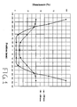
- Figure 1 refers to a display cabinet with traditional neon lighting system (without improvements but in any case widespread on the market) with 694 mm wide openings and shows the course of the lighting level on two different parallel target planes, arranged at different distances from the plane of the light sources.
- a plane is arranged at 150 mm from the source plane, whereas the other is arranged at 450 mm.
- the lighting is defined with relative values compared to the maximum illuminance value in the plane arranged at 150 mm.
- the traditional lighting systems do not allow a good distribution of light in the central zone of the door itself.
- central zone of opening A it is meant the area centred on the centre line axis of opening A along its main development dimension and that extends transversally to the centre line axis by about 80% of the total extension of the opening in such direction.
- side zones it is meant the residual portions of the opening not included in the central zone.
- a measure of the unevenness of light distribution may be given by the illuminance oscillation factor (ratio between minimum and maximum illuminance level in Lux) on the first target plane in the central zone of the door along the width dimension.
- a good illumination should allow obtaining an illuminance level in the top central zone higher than that of the side zones (absence of gap at the centre of the door), and taking as a reference a first target plane at a distance comprised between 10 and 15 cm from the source plane, an oscillation factor in the central zone higher than 0.3.
- the oscillation factor in the central zone is not higher than 0.2 and as already described above, in the side zones there is a higher lighting level than in the central zone.
- LED Light Emitting Diode
- LEDs have a luminous efficacy (lumen/Watt) that increases as temperature decreases (therefore ideal for applications in frozen and chilled display cabinets), unlike the neon for which a drastic drop of the luminous efficacy occurs for temperatures below nominal ones (between 25 and 35°C).
- the LEDs emit light at a much lower temperature than neon. As a consequence, the IR radiation share emitted is lower, with clear advantage for the thermal efficiency of the frozen display cabinet.
- the LEDs moreover have a much longer useful life than that of common neon.
- Another element to underline is the emission angle of the single LEDs, markedly lower than that of neon tubes, that normally emit evenly from all the surface of the tube or with cylindrical symmetry (360°).
- the LEDs substantially exhibit an emitting surface and in the first instance they may be compared to light sources that emit on a single hemisphere.
- the LED emission profile exhibits symmetries relative to the optical axis, which is normally orthogonal to the emitting surface of the semiconductor material.
- the optical axis coincides with the direction wherein the light is transmitted with the maximum intensity.
- LEDs do not emit on all the hemisphere but with angles comprised between 140° and 70°, although solutions with greater or smaller emission angles exist. Thanks to this, it is possible to use the light emitted by the light source without necessarily having to adopt special reflectors as in the case of neon tubes.
- LED lighting systems for display cabinets known today offer better performance in terms of energy efficiency compared to neon lighting systems, but still have the problem, although smaller, of the "illumination gap at the centre of the door" and do not allow improving decidedly the light distribution evenness on the first target plane.
- the known solutions adopted in LED systems in fact are substantially similar to those already adopted for neon lighting systems, that is, they envisage distributing the light of each light source on all the target plane or at least on half the target plane that relative to the centre line of the door is closer to the source, by especially designed lenses. Moreover, the lens cost is to the disadvantage of the inexpensiveness of the solutions.
- the object of the present invention therefore is to eliminate the disadvantages of the prior art mentioned above by providing a lighting system for frozen or chilled display cabinets which should allow obtaining an even illumination of the first target plane, in particular eliminating the illumination gap at the centre of the door while obtaining an oscillation factor above 0.3 in the central zone.
- a further object of the present invention is to provide a lighting system for frozen or chilled display cabinets which should be simple and inexpensive to make.
- a further object of the present invention is to provide a method for evenly lighting the loading space of a frozen or chilled display cabinet.
- FIG. 1 shows, with reference to a display cabinet provided with a traditional lighting system, the course of the illuminance level on two target planes arranged at different distances from the light source surface;
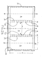
- FIG. 2a shows a front view of a frozen or chilled display cabinet provided with a lighting system according to the invention
- FIG. 2b shows a cutaway view of the display cabinet of figure 2a according to a plane parallel to the front face of the cabinet itself according to line II-II indicated in Figure 3 ;
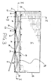
- FIG. 3 shows a cutaway plan view of the display cabinet of Figure 2a according to the line III - III indicated therein;
- Figure 4a shows a detail of the plan section of Figure 3 ;
- Figure 4b shows the same detail of Figure 4a and a partial front view (on a vertical plane) of an opening of the display cabinet, with highlighted the limits of a central area and of a centre line area of the opening itself;
- FIG. 5 shows a vertical side view of the display cabinet of Figure 1 according to the line V - V indicated in Figure 3 ;
- FIG. 6a e 6b show an example of emission profile of a lighting element of the system object of the present invention respectively on a horizontal emission plane and on a vertical emission plane;
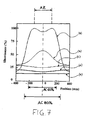
- FIG. 7 shows the course of the illuminance level into a display cabinet provided with the lighting system according to a particular solution of the invention on the first target plane and on target planes arranged at distances from the plane of the lighting elements greater than the first one;
- FIG. 8 shows a LED device with relative container and built-in primary lens
- FIG. 9 shows a lighting element of the lighting system according to a preferred embodiment of the invention that envisages the adoption of an elliptical lens as secondary lens;
- Figure 10 shows two lighting elements shown in Figure 9 associated to a mullion of a display cabinet
- FIG. 11 shows a lighting element of the lighting system according to a preferred embodiment of the invention that envisages the adoption of a reflector as secondary lens;
- FIG. 12 and 13 respectively show two different arrangements of the lighting element shown in Figure 11 in relation to a mullion of a display cabinet
- reference numeral 1 globally denotes a frozen or chilled display cabinet provided with a lighting system for the loading space according to the invention.
- frozen display cabinet refers to a display cabinet suitable for ensuring product storage temperatures below zero, typically not higher than-18°C.
- the expression “chilled display cabinet” refers to a display cabinet suitable for ensuring product storage temperatures above zero, typically comprised between 0°C and 4°C.
- the present invention is preferably applied to display cabinets (frozen or chilled type) with vertical development.
- the invention may also be applied to display cabinets (frozen or chilled type) with horizontal development.
- the invention may further be applied to display cabinets of the combined type, that is, comprising a portion of vertical display windows with glazed doors and a horizontal tank portion.
- the application of the invention should not be understood as limited to display cabinets of the closed type (that is, provided with closing doors of the loading space), as it may advantageously be applied to open cabinets also, since the arrangement of the lighting system into the cabinet may in any case be advantageous from the construction point of view.
- the lighting system according to the present invention may be used to replace the traditional lighting systems in retrofitting operations for display cabinets already manufactured or present on the market.
- display cabinet 1 is provided with three openings A, each closed by a transparent surface T consisting of a glazed door D of the wing type.
- the doors may be also of the sliding type.
- the display cabinets may be provided with one or more doors, as their number is not binding.
- the frozen display cabinets may further have any size and in particular they may be either with mainly vertical development or with mainly horizontal development.
- horizontal and vertical refer to the installation plane of the display cabinet, that is, they refer to the display cabinet in operating condition.
- openings A of display cabinet 1 have a rectangular shape and they lay on a substantially vertical plane, with closing doors provided with a flat glazed surface.
- the lighting system according to the present invention may also be applied to display cabinets having openings of any shape and in particular, square or with slightly curved sides.
- the glazed surface of the walls should not necessarily be flat, as it may for example be concave or convex in some portions or the entirety thereof.
- the display cabinet 1 is provided with a frame B that internally delimits a loading volume C for the display of goods.
- a loading volume C for the display of goods.
- Such volume C is divided into compartments S by a plurality of shelves R.
- the number and height distribution of the shelves is not binding for the purposes of the present invention.
- frame B frontally comprises a shaped structure E that defines the perimeter of the above openings A.
- structure E in particular comprises a vertical mullion M between one opening and the other that acts as stopping element for the doors.
- openings A may have any dimensions. However, particular reference shall be made to the dimensions currently selected by the market, which for a single rectangular opening envisage a width approximately comprised between 600 mm and 800 mm. These width dimensions allow a good compromise between the need of easy access to the loading space and the need of a limited space occupied by the doors in opening.
- the lighting system according to the invention provides for the loading space to be lighted from the interior.
- the lighting system according to the invention comprises for each opening A at least one pair of lighting elements 10, 20 suitable for lighting the loading space at least at opening A.
- the expression “at least at the opening” is understood to indicate that the main function of such elements 10 and 20 is to light the loading space within the limits defined by the opening perimeter projected orthogonally onto the loading space, but that nevertheless such elements may optionally contribute to lighting the loading space also at adjacent openings, as may happen for example in the case of display cabinets provided with more than one opening (see figure 3 ).
- a plurality of pairs of lighting elements 10, 20 may be provided for each opening A, with a variable number according to the dimensions of the same, as will be explained in detail hereinafter.
- the plurality of pairs of lighting elements is organised on at least two rows F1 and F2 arranged on the above two opposite portions L1, L2 of the perimeter of opening A, with the elements aligned in pairs transversally to the direction of said rows.
- the lighting elements 10, 20 are suitable to be arranged inside display cabinet 1 in such free space.
- the lighting elements 10, 20 are associated to the stopping mullions M of the closing doors.
- the lighting elements 10, 20 are integrated in the structure of mullion M.
- first target plane P1 the plane that delimits the loading space C at the front.
- the first target plane will be one.
- the first target plane will be suitably defined for each shelf or group of aligned shelves.
- the target plane as defined above is considered as reference for the effects of illumination since it is the most important for the display purpose and since, as already mentioned, the maximum phenomenon of the illumination gap at the centre of the door is on this plane (minimum distance of the goods from the light sources). In fact, the phenomenon attenuates progressively considering target planes increasingly farther from the openings, that is, from the lighting elements.
- the two lighting elements 10, 20 of each pair are suitable for being arranged on two opposite portions L1 and L2 of perimeter M of opening A relative to a centre line plane (indicated with Z in the annexed Figures) of the opening itself.
- centre line plane Z it is meant, in general, a plane substantially orthogonal to the first target plane P1 passing through opening A along the prevailing development direction of the latter, so as to divide it into two portions having a substantially similar area.
- each of the above two lighting elements 10, 20 is suitable for generating a light beam having an emission profile of the substantially Gaussian type, with optical axis x, y.
- the emission profile defines the course of the absolute or relative light intensity (for example, relative to the maximum intensity value) based on the angle of emission relative to the maximum emission direction.
- substantially Gaussian type means, in general, the emission profiles that exhibit a maximum of light intensity along at least one direction of emission (i.e., the optical axis), deviating wherefrom with increasingly angled emission directions the light intensity decreases, following a course comparable to a bell (symmetrical or asymmetrical).
- An example of this type of emission is shown in Figures 6a and 6b .
- the definition is understood to include emission profiles with courses exhibiting irregularities, such as oscillations or local maximum and minimum, or asymmetries relative to the optical axis.
- FWHM Full Width at Half Maximum
- the emission profile of each lighting element is adjusted on the basis of the illuminance level to be obtained on the first target plane.
- the emission profile may also be differentiated according to the emission plane of the light.
- Figures 6a and 6b refer to the emission profile of the same lighting element according to a preferred embodiment, wherein in particular the diagram of Figure 6a refers to the profile on a first emission plane (horizontal), whereas the diagram of Figure 6b refers to the profile on a second emission plane (vertical).
- each lighting element 10, 20 comprises a light source at the solid state.
- such light source consists of a LED.
- the LEDs may be compared in the first instance to light sources that emit on a single hemisphere, with emission profile "substantially Gaussian type". Relative to the optical axis, the LED can emit up to angles comprised between 140° and 70°, although solutions with greater or smaller emission angles exist.
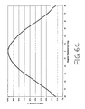
- Figure 6c shows the emission profile of a LED used in a particular embodiment of the invention, wherein an FWHM equal to about 120° is seen.
- LEDs suitably encapsulated into containers or package (indicated with reference numeral 100 in Figure 8 ) suitable for being welded on printed circuit plates with surface mounting or through rheophore technology, as well as to use LEDs mounted using the "chip on board” technology, which allows the direct mounting of the semiconductor on the plates intended for providing support for the electrical supply circuit also.
- the LEDs are supplied by the manufacturers already provided with a primary lens (indicated with reference numeral 110 in the annexed Figures) which is substantially suitable for offering a first concentration of the LED emission profile and which mechanically integrates with the container or package of the LED.
- the use of the primary lens supplied by the LED manufacturer is possible but not necessary.
- LED with white emission are used, characterised by a specific color temperature preferably, but not necessarily comprised between 4,000 and 6,500 K.
- each lighting element 10, 20 comprises optical means suitable for modifying the emission profile of the light source.
- optical means may also be suitable for differentiating the emission profile with reference to different emission planes.
- the lighting elements 10, 20 of each pair are arranged so that the optical axes x, y of the light beams generated thereby cross each other and cross the centre line plane Z before intercepting the first target plane P1, as illustrated in Figure 4a that refers to a preferred embodiment of the invention.
- the centre line plane Z divides the first target plane P1 into two portions, whereof we will call “first portion” P1' the one closest to the first element 10 of a pair of lighting elements, and “second portion” P1" the remaining portion, that is, the one closest to the second element 20 (see Figure 4b ).
- the lighting elements 10, 20 of each pair are arranged so that the first element 10 is suitable for mainly lighting the second portion P1" (that is, intercepts it with its optical axis x), and vice versa that the second element 20 is suitable for mainly lighting the first portion P1' (that is, intercepts it with its optical axis y).
- central zone AC of opening A it is meant the area arranged astride of the centre line axis of opening A (i.e. trace of the centre line plane Z on the plane of opening A) along its main development dimension and that extends transversally to the centre line axis by about 80% of the total extension of the opening in such cross direction.
- the phenomenon just described is favourably increased when the lighting elements 10 and 20 are arranged so that the optical axes x and y meet the first target plane P1 within the limits defined by the orthogonal projection of perimeter M of opening A on the first target plane P1.
- a centre line area AZ as the area of the first target plane P1 arranged astride of the centre line axis and laterally delimited by two lines Y1 and X1 parallel to such axis and respectively passing by the intercept of the optical axis x of the first lighting element 10 on the first target plane and by the intercept of the optical axis y of the second lighting element 20.
- Side areas AL mean the residual areas not included in the centre line area AZ.
- the centre line area AZ is rectangular and the above two lines X1 and Y1 are two vertical lines, as illustrated in figure 4b .
- the crossing of the optical axes x, y makes the emitted beams strike in a non orthogonal manner on the first target plane.
- the centre line area AZ - relative to the lighting element - is always at a smaller distance relative to the side area AL with emission angle relative to the optical axis x, y being equal.
- the emission angle relative to the optical axis x being equal, the light that intercepts the centre line area AZ has covered a smaller distance than the light that intercepts the side zone AL. This has the positive effect of favouring the lighting of the centre line zone AZ and thus reduce the illumination gap phenomenon.
- the crossing of the optical axes allows obtaining greater evenness of distribution of the light on all the target plane compared to the prior art solutions that on the contrary do not envisage the beam crossing.
- the beam crossing allows attenuating the effect related to the fact that different points of a same target half plane are at different distances from the main lighting element (intended as the element primarily dedicated to the lighting of the half plane considered).
- the emission profile of each of the two lighting elements 10, 20 is defined so that on the first target plane P1, parallel to the segment that connects the intercepts of the optical axes x, y to the first target plane P1, the lower intensity of the light emitted along angled directions relative to the optical axis x, y is compensated by the smaller distance between the above lighting element 10, 20 and the first target plane P1 along the above angled directions, as well as the contribution resulting from the overlapping with the light beam emitted by the other lighting element (20, 10) in order to obtain a lighting oscillation factor higher than 0.3.
- the lighting elements 10, 20 generate restricted light beams on an emission plane orthogonal to the first target plane P1 and passing by the alignment axis W of two coupled lighting elements (meaning that their axes intersect).
- restricted beam it is meant a beam corresponding to an emission profile with FWHM below 20° in a predefined emission plane.
- the two lighting elements (10, 20) are arranged on opposite portions L1, L2 of the perimeter of the opening A between which the distance is minimal.
- Figure 3 which refers to display cabinets with rectangular openings having a main development in vertical direction, that is, in the direction of the height, the two lighting elements 10 and 20 of every single pair are associated to mullions M of the closing doors of openings A, aligned in the direction of width L of openings A (horizontally).
- the lighting elements 10 and 20 of each pair are preferably aligned in the direction of height H of openings A (vertically).
- openings A are square or in any case the ratio between height H and length L is close to 1, the lighting elements 10 and 20 may be aligned without distinction in vertical direction or in horizontal direction.
- the two lighting elements of each pair are aligned parallel to the first target plane P1 and are arranged so that their optical axes x, y cross each other on the centre line plane Z.
- the lighting elements are arranged symmetrically relative to the centre line plane Z of the opening.
- the lighting obtained has a course substantially symmetrical and centred on the centre line plane Z of opening A.
- the two lighting elements (10, 20) are identical to each other, at least by emission profile and power.
- embodiments may be envisaged wherein the lighting elements are not identical and are not arranged and orientated symmetrically relative to the centre line plane Z of opening A. This situation may occur in the case of display cabinets having asymmetrical frames (in the case of innovative designs) where two coupled lighting elements may not be placed at the same distance from the first target plane.
- the emission profile and the power of the single lighting elements as well as the orientation of the optical axes shall be suitably adjusted so as to obtain an illumination of the first target plane P1 having a course substantially symmetrical and centred on the centre line plane Z of opening A.
- the optical axes x and y of each pair of lighting elements 10, 20 lie on a horizontal plane.
- the optical axes lie on vertical planes.
- optical axes lie on inclined planes (neither horizontal nor vertical).
- the crossing between optical axes it is preferable for the crossing between optical axes to involve only pairs of lighting elements, and even more preferably, pairs of elements arranged on two opposite sides of the perimeter of the opening between which the distance is minimal.
- each opening A there is provided a plurality of lighting elements organised on two rows F1 and F2 along the two greater sides of the opening.
- Elements 10, 20 are horizontally aligned in pairs, that is, in the direction of the width.
- the lighting elements may be provided not only in single rows, but also in matrices.
- the crossing of the optical axes x and y is only provided in the horizontal direction (width), where in combination with the crossing it is suitable to arrange restricted light beams.
- the lighting in horizontal direction has the constraint given by the width dimension of the opening, a dimension that sets the minimum interdistance possible in horizontal direction between the lighting elements, unless elements are provided in the opening gap.
- the beam width in the vertical direction there is the opposite need compared to the horizontal dimension.
- the more restricted are the beams the smaller is the area lighted by the single beam, and therefore the greater must be the number of lighting elements to use to ensure suitable lighting evenness, to the disadvantage of the inexpensiveness.
- each lighting element 10, 20 comprises optical means suitable for differentiating the emission profile of the light source (preferably but not necessarily a LED) relative to a main plane, passing by the alignment axis w of two lighting elements 10, 20 and by the optical axis x, y, and relative to a secondary plane, incident said main plane along the optical axis x, y preferably in orthogonal direction.
- the light source preferably but not necessarily a LED
- the optical axes x, y lie on a horizontal plane and the alignment axis w is horizontal.
- the main plane therefore is a horizontal plane, while the secondary plane is a vertical plane.
- the optical means comprise at least one elliptical lens 120, according to the preferred embodiment of the invention illustrated in figures 9 and 10 .
- the optical means may comprise a reflector 130 as an alternative to the elliptical lens according to the alternative embodiment of the invention illustrated in figures 11 to 13 .
- the elliptical lens 120 and/or the reflector 130 may be associated to the LED also retaining the primary lens 110 provided by the manufacturer. However, it is also possible to use only the elliptical lens and/or the reflector without applying the primary lens 110.
- the optical means (which may comprise or not the primary lens 110) are selected so that the emission profile on the main plane exhibits a value of FWHM lower than the value of FWHM on the secondary plane.
- the optical means may be selected so that the emission profile on the secondary plane exhibits an FWHM as wide as possible.
- elliptical lenses and reflectors of the commercial type may be used to the advantage of the inexpensiveness of construction.
- values of FWHM comprised between 35° and 120°, and even more preferably between 40° and 90° are preferable for the emission profile on the secondary plane.
- the interdistance between two lighting elements of a same row is comprised between 55mm and 200 mm, and preferably between 75 mm and 125 mm.
- the display cabinets currently widespread on the market envisage one or more openings with mainly vertical development (height > width), preferably of rectangular shape, the perimeter whereof comprises two vertical parallel sides (opposite portions L1 and L2) distant between 600 mm and 800 mm from each other.
- the above sides are defined by structural elements (mullions) suitable for acting as stop for the seals of the closing doors and lying on a plane parallel to the first target plane P1 and distant between 100 mm and 150 mm from the latter.
- the lighting system according to the invention provides for the lighting elements to be organised on two rows F1 and F2 along the vertical sides L1 and L2 of the openings, aligned in pairs in the width direction.
- the optical axes x, y of each lighting element 10, 20 form with the first target plane P1 an inclination angle ⁇ x, ⁇ y comprised between 7° and 18°, and preferably between 8° and 16°.
- lighting elements are provided suitable for generating an emission profile on a horizontal plane having an FWHM comprised between 6° and 20°, and preferably between 10° and 16°.
- the lighting elements exhibit an emission profile on a vertical plane different from the profile on the horizontal plane.
- the emission profile exhibits an FWHM comprised between 35° and 120°, and even more preferably between 40° and 90°.
- the interdistance between two lighting elements of a same row F1, F2 is preferably comprised between 55 mm and 200 mm, and even more preferably between 75 mm and 125 mm.
- FIGs of Figure 7 were obtained on a display cabinet with rectangular openings having a width of about 700 mm and height of about 1700 mm, with first target plane arranged at about 150 mm from the plane of the openings.
- the lighting system according to the invention provides each opening two rows of LEDs arranged on the greater sides of the openings. Each row comprises 20 lighting elements distributed vertically on a length of about 1500 mm.
- the lighting elements are identical to each other and are oriented so that their optical axes x and y lie on horizontal planes and, crossing each other in the centre line plane, they form an inclination angle ⁇ x, ⁇ y of about 11° with the first target plane P1.
- Each lighting element comprises a LED and an elliptical lens 15X40, that is, suitable for generating an emission profile with horizontal FWHM of 15° and with vertical FWHM of 40°.
- a white light LED was used as a LED, with color temperature of 5200 Kelvin which if powered at 350mA DC, absorbs a power of about 1.2 W.
- the optical means comprise the primary lens 110 supplied by the manufacturer (which in particular determines the emission profile illustrated in Figure 6c ) and an elliptical lens suitable for differentiating the emission in the primary plane and in the secondary plane (as illustrated for example in the diagrams of Figures 6a and 6b ).
- a lens moulded of plastic material was used as elliptical lens with external dimensions corresponding to a cube of about 11 mm side.
- This type of lenses is set up in particular to be glued to the printed circuit where the LED is mounted with a surface mounting welding process.
- the invention allows obtaining a good illumination evenness.
- the problem of the illumination gap at the centre of the door was solved and a illuminance oscillation factor higher than 0.3 was obtained in the central zone.
- An object of the present invention is a method for lighting the loading space of a frozen or chilled display cabinet as defined above.
- Such method comprises an operating step (a) of arranging for each opening A at least a pair of lighting elements 10, 20 into the display cabinet on two portions L1, L2 of the opening perimeter opposite relative to a centre line plane Z. Such elements are arranged in the space comprised between opening A and the first target plane P1.
- Each of said two lighting elements 10, 20 generate a light beam having an emission profile of the substantially Gaussian type, with optical axis x, y.
- the method further comprises an operating step (b) of orientating the optical axes x, y of the light beams generated by the two lighting elements 10, 20 so that the optical axes x, y cross each other and cross the centre line plane Z before intercepting the first target plane P1.
- the method comprising the operating step (c) of adjusting the emission profile of each lighting element 10, 20 so that on the first target plane P1, parallel to the segment that connects the intercepts of the optical axes x, y with the above first target plane, the lower intensity of the light emitted along angled directions relative to the optical axis x, y is compensated by the smaller distance between the lighting element 10, 20 and the first target plane P1 along the above angled directions, as well as by the contribution resulting from the overlapping with the light beam emitted by the other lighting element 20, 10 so as to obtain an illuminance oscillation factor higher than 0.3.
- a plurality of pairs of lighting elements 10, 20 is arranged for each opening, the first and second elements 10 and 20 of each pair being respectively arranged on a first row F1 and on a second row F2.
- the two rows F1, F2 are arranged on two opposite portions L1, L2 of the perimeter of opening A.
- each lighting element 10, 20 comprises a light source at the solid state, preferably a LED.
- each light source is associated to optical means suitable for differentiating the emission profile of the light source relative to a main plane, passing by the alignment axis w of two lighting elements 10, 20 and by the optical axis x, y, and relative to a secondary plane, incident said main plane along the optical axis x, y preferably in orthogonal direction.
- the emission profile on the main plane exhibits an FWHM value below the FWHM value on the secondary plane.
Landscapes
- Engineering & Computer Science (AREA)
- General Engineering & Computer Science (AREA)
- Physics & Mathematics (AREA)
- Thermal Sciences (AREA)
- Non-Portable Lighting Devices Or Systems Thereof (AREA)
Priority Applications (1)
| Application Number | Priority Date | Filing Date | Title |
|---|---|---|---|
| EP08425102A EP2092859A1 (de) | 2008-02-20 | 2008-02-20 | Beleuchtungsverfahren und Vorrichtung für Kältegerät |
Applications Claiming Priority (1)
| Application Number | Priority Date | Filing Date | Title |
|---|---|---|---|
| EP08425102A EP2092859A1 (de) | 2008-02-20 | 2008-02-20 | Beleuchtungsverfahren und Vorrichtung für Kältegerät |
Publications (1)
| Publication Number | Publication Date |
|---|---|
| EP2092859A1 true EP2092859A1 (de) | 2009-08-26 |
Family
ID=39587294
Family Applications (1)
| Application Number | Title | Priority Date | Filing Date |
|---|---|---|---|
| EP08425102A Withdrawn EP2092859A1 (de) | 2008-02-20 | 2008-02-20 | Beleuchtungsverfahren und Vorrichtung für Kältegerät |
Country Status (1)
| Country | Link |
|---|---|
| EP (1) | EP2092859A1 (de) |
Cited By (4)
| Publication number | Priority date | Publication date | Assignee | Title |
|---|---|---|---|---|
| AT12664U1 (de) * | 2010-08-20 | 2012-09-15 | Siteco Beleuchtungstech Gmbh | Beleuchtungseinrichtung für ein kühlmöbel |
| WO2016102012A1 (en) * | 2014-12-23 | 2016-06-30 | Carrier Corporation | Refrigerated sales furniture |
| US9514663B2 (en) | 2012-07-30 | 2016-12-06 | Ultravision Technologies, Llc | Method of uniformly illuminating a billboard |
| US10741107B2 (en) | 2013-12-31 | 2020-08-11 | Ultravision Technologies, Llc | Modular display panel |
Citations (5)
| Publication number | Priority date | Publication date | Assignee | Title |
|---|---|---|---|---|
| WO2001056336A1 (en) * | 2000-01-25 | 2001-08-02 | A & T Engineering Company, Inc. | Process for manufacturing a neon tube, and related low temperature lighting system |
| US6578978B1 (en) * | 1999-06-07 | 2003-06-17 | Specialty Equipment Companies, Inc. | Display case having a mullion with recessed light fixtures |
| US20050265019A1 (en) * | 2004-05-26 | 2005-12-01 | Gelcore Llc | LED lighting systems for product display cases |
| WO2006126250A1 (ja) * | 2005-05-23 | 2006-11-30 | Itl Corporation | 展示ケース用照明装置 |
| DE102005057154A1 (de) * | 2005-11-30 | 2007-05-31 | BSH Bosch und Siemens Hausgeräte GmbH | Haushaltsgerät mit einem von einer Glastür her beleuchteten Innenraum |
-
2008
- 2008-02-20 EP EP08425102A patent/EP2092859A1/de not_active Withdrawn
Patent Citations (5)
| Publication number | Priority date | Publication date | Assignee | Title |
|---|---|---|---|---|
| US6578978B1 (en) * | 1999-06-07 | 2003-06-17 | Specialty Equipment Companies, Inc. | Display case having a mullion with recessed light fixtures |
| WO2001056336A1 (en) * | 2000-01-25 | 2001-08-02 | A & T Engineering Company, Inc. | Process for manufacturing a neon tube, and related low temperature lighting system |
| US20050265019A1 (en) * | 2004-05-26 | 2005-12-01 | Gelcore Llc | LED lighting systems for product display cases |
| WO2006126250A1 (ja) * | 2005-05-23 | 2006-11-30 | Itl Corporation | 展示ケース用照明装置 |
| DE102005057154A1 (de) * | 2005-11-30 | 2007-05-31 | BSH Bosch und Siemens Hausgeräte GmbH | Haushaltsgerät mit einem von einer Glastür her beleuchteten Innenraum |
Cited By (19)
| Publication number | Priority date | Publication date | Assignee | Title |
|---|---|---|---|---|
| AT12664U1 (de) * | 2010-08-20 | 2012-09-15 | Siteco Beleuchtungstech Gmbh | Beleuchtungseinrichtung für ein kühlmöbel |
| US9732932B2 (en) | 2012-07-30 | 2017-08-15 | Ultravision Technologies, Llc | Lighting assembly with multiple lighting units |
| US9812043B2 (en) | 2012-07-30 | 2017-11-07 | Ultravision Technologies, Llc | Light assembly for providing substantially uniform illumination |
| US9524661B2 (en) | 2012-07-30 | 2016-12-20 | Ultravision Technologies, Llc | Outdoor billboard with lighting assemblies |
| US9542870B2 (en) | 2012-07-30 | 2017-01-10 | Ultravision Technologies, Llc | Billboard and lighting assembly with heat sink and three-part lens |
| US9659511B2 (en) | 2012-07-30 | 2017-05-23 | Ultravision Technologies, Llc | LED light assembly having three-part optical elements |
| US9685102B1 (en) | 2012-07-30 | 2017-06-20 | Ultravision Technologies, Llc | LED lighting assembly with uniform output independent of number of number of active LEDs, and method |
| US9734737B2 (en) | 2012-07-30 | 2017-08-15 | Ultravision Technologies, Llc | Outdoor billboard with lighting assemblies |
| US10891881B2 (en) | 2012-07-30 | 2021-01-12 | Ultravision Technologies, Llc | Lighting assembly with LEDs and optical elements |
| US9514663B2 (en) | 2012-07-30 | 2016-12-06 | Ultravision Technologies, Llc | Method of uniformly illuminating a billboard |
| US9734738B2 (en) | 2012-07-30 | 2017-08-15 | Ultravision Technologies, Llc | Apparatus with lighting units |
| US10410551B2 (en) | 2012-07-30 | 2019-09-10 | Ultravision Technologies, Llc | Lighting assembly with LEDs and four-part optical elements |
| US9947248B2 (en) | 2012-07-30 | 2018-04-17 | Ultravision Technologies, Llc | Lighting assembly with multiple lighting units |
| US10223946B2 (en) | 2012-07-30 | 2019-03-05 | Ultravision Technologies, Llc | Lighting device with transparent substrate, heat sink and LED array for uniform illumination regardless of number of functional LEDs |
| US10339841B2 (en) | 2012-07-30 | 2019-07-02 | Ultravision Technologies, Llc | Lighting assembly with multiple lighting units |
| US10741107B2 (en) | 2013-12-31 | 2020-08-11 | Ultravision Technologies, Llc | Modular display panel |
| CN107105907A (zh) * | 2014-12-23 | 2017-08-29 | 开利公司 | 冷藏商品展示柜 |
| CN107105907B (zh) * | 2014-12-23 | 2020-03-10 | 开利公司 | 冷藏商品展示柜 |
| WO2016102012A1 (en) * | 2014-12-23 | 2016-06-30 | Carrier Corporation | Refrigerated sales furniture |
Similar Documents
| Publication | Publication Date | Title |
|---|---|---|
| US20070159820A1 (en) | Light emitting diode lighting assembly | |
| US7857473B2 (en) | Open showcase with light emitting diodes | |
| US7845818B2 (en) | Showcase | |
| US20130120991A1 (en) | Lighting module for illuminating traffic routes, and traffic route luminaire | |
| ES2397876A9 (es) | Conjunto de luces de led de alta eficacia para un mueble de expendeduría. | |
| CN101514861A (zh) | 陈列柜 | |
| US9086204B2 (en) | Reflector, illuminator and the use thereof | |
| US20120063125A1 (en) | Display case lighting | |
| US20080205040A1 (en) | Open showcase | |
| CN104613415A (zh) | 透镜、led模组及使用该led模组的照明系统 | |
| US20090059597A1 (en) | Energy-saving lampshade with even light distribution | |
| CN204678147U (zh) | 发光二极管灯箱 | |
| EP3816498B1 (de) | In schaukasten verwendetes streifenlicht | |
| WO2012105315A1 (ja) | 棚板用導光素子および照明装置 | |
| US8434889B2 (en) | Lighted display case having reduced glare | |
| WO2020254652A1 (en) | Shelf lamp with illuminated identification plate | |
| EP2168461A1 (de) | Präsentationsvorrichtung | |
| CN217082290U (zh) | 防眩光设计的独立柜灯盘 | |
| JP2013232285A (ja) | 照明装置 | |
| CN102080792A (zh) | 反射式led天幕灯 | |
| CN101915380B (zh) | 一种led灯箱光源系统 | |
| CN213686680U (zh) | 一种仿蝴蝶翼的双偏条纹线性透镜 | |
| CN202756954U (zh) | 发光体 | |
| JP2009279134A (ja) | ショーケース | |
| JP7412121B2 (ja) | 照明装置 |
Legal Events
| Date | Code | Title | Description |
|---|---|---|---|
| PUAI | Public reference made under article 153(3) epc to a published international application that has entered the european phase |
Free format text: ORIGINAL CODE: 0009012 |
|
| AK | Designated contracting states |
Kind code of ref document: A1 Designated state(s): AT BE BG CH CY CZ DE DK EE ES FI FR GB GR HR HU IE IS IT LI LT LU LV MC MT NL NO PL PT RO SE SI SK TR |
|
| AX | Request for extension of the european patent |
Extension state: AL BA MK RS |
|
| 17P | Request for examination filed |
Effective date: 20100224 |
|
| 17Q | First examination report despatched |
Effective date: 20100331 |
|
| AKX | Designation fees paid |
Designated state(s): AT BE BG CH CY CZ DE DK EE ES FI FR GB GR HR HU IE IS IT LI LT LU LV MC MT NL NO PL PT RO SE SI SK TR |
|
| STAA | Information on the status of an ep patent application or granted ep patent |
Free format text: STATUS: THE APPLICATION IS DEEMED TO BE WITHDRAWN |
|
| 18D | Application deemed to be withdrawn |
Effective date: 20110901 |