EP2092864A2 - Kochofenvorrichtung, im Besonderen für die Zubereitung von Kebab - Google Patents
Kochofenvorrichtung, im Besonderen für die Zubereitung von Kebab Download PDFInfo
- Publication number
- EP2092864A2 EP2092864A2 EP09152729A EP09152729A EP2092864A2 EP 2092864 A2 EP2092864 A2 EP 2092864A2 EP 09152729 A EP09152729 A EP 09152729A EP 09152729 A EP09152729 A EP 09152729A EP 2092864 A2 EP2092864 A2 EP 2092864A2
- Authority
- EP
- European Patent Office
- Prior art keywords
- cooking
- group
- shelf
- rotation axis
- stem
- Prior art date
- Legal status (The legal status is an assumption and is not a legal conclusion. Google has not performed a legal analysis and makes no representation as to the accuracy of the status listed.)
- Withdrawn
Links
Images



Classifications
-
- F—MECHANICAL ENGINEERING; LIGHTING; HEATING; WEAPONS; BLASTING
- F24—HEATING; RANGES; VENTILATING
- F24C—DOMESTIC STOVES OR RANGES ; DETAILS OF DOMESTIC STOVES OR RANGES, OF GENERAL APPLICATION
- F24C15/00—Details
- F24C15/16—Shelves, racks or trays inside ovens; Supports therefor
- F24C15/164—Rotisserie spits inside ovens
-
- A—HUMAN NECESSITIES
- A47—FURNITURE; DOMESTIC ARTICLES OR APPLIANCES; COFFEE MILLS; SPICE MILLS; SUCTION CLEANERS IN GENERAL
- A47J—KITCHEN EQUIPMENT; COFFEE MILLS; SPICE MILLS; APPARATUS FOR MAKING BEVERAGES
- A47J37/00—Baking; Roasting; Grilling; Frying
- A47J37/04—Roasting apparatus with movably-mounted food supports or with movable heating implements; Spits
- A47J37/043—Roasting apparatus with movably-mounted food supports or with movable heating implements; Spits with food supports rotating about a vertical axis
Definitions
- the present invention relates to an oven cooking device, specially for making kebabs.
- the kebab especially, a meat-based dish typical of Turkish, Persian and Arab cuisine has become particularly widespread.
- kebab there are two types of kebab, the "doner kebab” in which a piece of meat rotates on a vertical roasting spit, and the “shish kebab", in which a number of skewers of meat surround a vertical roasting spit.
- the purpose of the present invention is to make an oven cooking device suitable for making kebabs.
- FIG. 1 shows an oven cooking device, according to a first embodiment of the present invention, suitable for making a doner kebab;
- FIG. 2 shows the oven cooking device according to a further embodiment, suitable for making a shish kebab
- FIG. 3 shows a shelf with a transmission holder box of the device in figures 1 and 2 ;
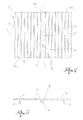
- FIG. 4 and 5 respectively show a view from above and a lateral view of the shelf in figure 3 ;
- FIG. 6a and 6b show lateral views of a cooking unit of the devices in figures 1 and 2 .
- reference numeral 1 globally denotes an oven cooking device, specially for making kebabs.
- the device 1 is suitable for accommodating entirely inside the cooking chamber of an oven, defined by a door which opens, by lateral walls, by a rear wall, by a bottom and by a top.
- the device 1 comprises a shelf 2 suitable for being supported by channels made in the sides of the cooking chamber, at a predefined height from the bottom.
- the oven has an electric motor which provides a mechanical torque at a power take-off, generally positioned on one of the walls defining the cooking chamber.
- the power take-off is able to transmit a rotation along a horizontal rotation axis X, parallel to the bottom of the cooking chamber and perpendicular to the wall which the power take-off is positioned on.
- the shelf 2 comprises a rectangular or square frame 3, which extends in length along a longitudinal axis L, parallel to the horizontal rotation axis X when the shelf is in the cooking chamber, and in width along a transversal axis T, perpendicular to the longitudinal axis L.
- the frame 3 is formed of transversal rods 3a, 3b spaced along the longitudinal axis L, and longitudinal rods 3d, spaced along the transversal axis T.
- the transversal rod 3a proximal to the rear wall of the cooking chamber of the oven when the shelf is inserted in said chamber has a section 3a' curved towards the lower side of the shelf 2.
- the shelf 2 also comprises a number of wires 4, parallel to the longitudinal axis L, spaced along the transversal axis T.
- the shelf 2 has an upper side and a lower side.
- the shelf On the lower side the shelf has a number of supports 5, for instance in the form of wires bent into a U-shape, each support being attached to a wire of the shelf, for instance, welded.
- supports 5 for instance in the form of wires bent into a U-shape, each support being attached to a wire of the shelf, for instance, welded.
- four supports are provided, two on one wire and two on another.
- the primary wires 6, 8 are spaced at a different distance to the distance between the other wires of the shelf.
- the curved section 3a' of the longitudinal rod 3a of the shelf 2 is positioned between said primary wires 6, 8 of the shelf 2.
- the shelf 2 comprises at least one stop 10, positioned between the primary wires 6, 8; for instance, the stop 10 is composed of a wire shaped into a U, which joins the two primary wires 6, 8.
- the height of the stop 10 is lower than the height of the supports 5, so that when the shelf 2 is placed on a flat surface it rests firmly on the supports 5 and the stops 10 do not interfere with them.
- the shelf 2 comprises two stops 10, spaced along the longitudinal axis L.
- the two primary wires 6, 8 and the two stops 10 define between them a housing compartment 12.
- the device 1 also comprises a cooking group 20 suitable for laying on the shelf 2 in a removable manner, connecting with the power take-off of the motor and supporting the meat to be cooked.
- the cooking group 20 is able to connect to the power take-off and to transform the rotation around the horizontal rotation axis X into a rotation around a vertical rotation axis Z, perpendicular to the horizontal rotation axis X.
- the cooking group 20 comprises means of transmission able to take the rotatory movement along a horizontal rotation axis from the power take-off and transform it into rotatory movement along said vertical rotation axis.
- the means of transmission comprise a stem 22, extending mainly along the vertical rotation axis Z, preferably pointed so as to spear the piece of meat, a take-off shaft 24, perpendicular to the stem 22, and a transmission holder box 26, where the stem and the take-off shaft converge.
- the cross-section of the stem 22, made on a plane perpendicular to the vertical rotation axis, is polygonal, for instance square or rectangular; according to another embodiment, said cross-section is circular.
- the means of transmission comprise a system of transmission gears, housed in the transmission holder box 26, connected to the stem 22 and to the take-off shaft 24, to transfer the rotatory movement from the shaft to the stem.
- the cooking group 20 may be positioned on the shelf 2; specifically the transmission holder box 26 is lodged in the housing compartment 12 of the shelf, so that the take-off shaft 24 is aligned with the horizontal rotation axis X.
- Said take-off shaft 24 extends along said horizontal rotation axis X so as to enable mechanical connection with the power take-off of the motor.
- the take-off shaft 24 near its extremity connecting to the power take-off, rests on the curved section 3a' of the transversal rod 3a of the shelf 2, for better support.
- the transmission holder box 26 may be lodged between the primary wires 6, 8, so as to protrude from the lower side of the shelf 2.
- This makes it possible to reduce the vertical dimensions of the cooking device, preventing problems of space.
- the transmission box 26 comprises a main body 28, which the transmission gears are lodged in and which is positioned between the primary wires 6, 8 of the shelf, and a pair of support wings 30, protruding from the main body 28, along the transversal axis T of the shelf.
- Said support wings 30 rest on the wires of the shelf 2, forming a stable support of the transmission devices, acting against the rotation of the cooking group driven by the motor.
- the main body is near, almost against, the stops 10 of the shelf.
- such stops also increase the stability of the cooking group on the shelf.
- the support wings 30 prevent the cooking group 20 from overturning in relation to the horizontal rotation axis X; in the meantime, the stops 10, hitting against the main body of the transmission box, prevent the cooking group from overturning in relation to the transversal axis T of the shelf.
- the transmission box 26 comprises, in addition, a spacer 32, which surmounts the main body 28, at the foot of the stem 22.
- the cooking group 20 comprises an oven tray 40, for instance in the shape of a dish, fitted onto the stem 22 in a detachable manner.
- the oven tray 40 is fitted onto the spacer 32 of the transmission box 26.
- the oven tray 40 rests on the wires of the shelf.
- the oven tray 40 rests on the transmission holder box 26, remaining raised in relation to the wires of the shelf.
- the oven tray 40 comprises, from the vertical rotation axis Z towards the peripheral rim, a connection plate 42, an annular flared portion 44, flared downwards, and an annular collection portion 46, with a raised edge 48.
- the flared portion 44 allows the liquids generated during cooking of the meat to drain off into the collection portion 46, acting as a collection tank, by virtue of the raised edge 48.
- the cooking group 20 comprises in addition a lower flange 50, in the form of a dish, fitted onto the stem 22 in a detachable manner, above the oven tray 40.
- the lower flange 50 acts as a support for the meat speared by the stem 22 or, as will be described below, as a support for the skewers for a shish kebab.
- the lower flange 50 is vertically spaced from the oven tray 40, in that it rests on the spacer 32 of the transmission holder box 26.
- the lower flange comprises, from the vertical rotation axis Z towards the peripheral rim, a central plate 52, a flared crown 54 and a flat crown 56.
- the lower flange 50 extends radially so that the peripheral rim is inside the peripheral rim of the oven tray below, and specifically so that the flat crown 56 terminates with its peripheral rim in correspondence with the collection portion 46 of the oven tray below 40.
- the lower flange 50 comprises a number of holes 58, which surround the vertical rotation axis Z.
- the holes 58 are positioned along an imaginary circumference concentric to the vertical rotation axis Z, for instance on the flat crown 56 of the lower flange 50.
- the cooking group 20 comprises accessories for completing the cooking of a shish kebab.
- Said completion accessories comprise an upper flange 70, in the form of a plate, fitted onto the stem in a detachable manner 22 and attached to this in an adjustable manner so as to maintain the desired height from the lower flange underneath 50.
- the upper flange 70 comprises a flat plate 72 and an attachment support 74, for instance in the form of a U-shaped profile, attached to the plate 72 so as to be traversed by the stem 22.
- the upper flange 70 comprises in addition a key 76, which can be screwed into the attachment element 74, so as to engage by friction the stem 22, fixing the upper flange at the desired height.
- the upper flange 70 has in addition a number of seats for skewers 78, made along the peripheral rim of the plate 72 in the form of indentations of the same.
- Said completion accessories comprise, in addition, a number of skewers 80, that is of rods to spear in succession pieces of meat or vegetables.
- Said skewers 80 have a ring-shaped upper extremity 82, bent into the form of an open ring to give the desired structural flexibility.
- Said ring-shaped extremity 82 is suitable for snap-insertion into the respective skewer seat 78.
- the skewer 80 is of such a length that the other extremity, that is the lower extremity 84 is inserted in the respective hole 58 of the lower flange 50, even when the upper flange is fixed to the stem 22 at the maximum upper height.
- the pieces of meat are put onto the skewers 80 and positioned vertically.
- the components of the device are made in steel.
- the cooking device described above makes it possible to make a kebab in a traditional domestic oven.
- preparation is greatly simplified, in that the device can be extracted from the cooking chamber of the oven for the preparation of the foods to be cooked, for instance on a table or kitchen counter.
- the size of the cooking device and of the cooking group is limited, to facilitate use in small ovens too.
- the cooking group rests firmly on the shelf.
- the device makes it possible to perform such cooking with limited soiling of the cooking chamber, the liquids being appropriately channelled.
Landscapes
- Engineering & Computer Science (AREA)
- Chemical & Material Sciences (AREA)
- Combustion & Propulsion (AREA)
- Mechanical Engineering (AREA)
- General Engineering & Computer Science (AREA)
- Baking, Grill, Roasting (AREA)
Applications Claiming Priority (1)
| Application Number | Priority Date | Filing Date | Title |
|---|---|---|---|
| ITBS20080033 ITBS20080033A1 (it) | 2008-02-13 | 2008-02-13 | Dispositivo di cottura per forno, in particolare per la preparazione di kebab |
Publications (2)
| Publication Number | Publication Date |
|---|---|
| EP2092864A2 true EP2092864A2 (de) | 2009-08-26 |
| EP2092864A3 EP2092864A3 (de) | 2010-08-25 |
Family
ID=40291479
Family Applications (1)
| Application Number | Title | Priority Date | Filing Date |
|---|---|---|---|
| EP09152729A Withdrawn EP2092864A3 (de) | 2008-02-13 | 2009-02-12 | Kochofenvorrichtung, im Besonderen für die Zubereitung von Kebab |
Country Status (2)
| Country | Link |
|---|---|
| EP (1) | EP2092864A3 (de) |
| IT (1) | ITBS20080033A1 (de) |
Cited By (5)
| Publication number | Priority date | Publication date | Assignee | Title |
|---|---|---|---|---|
| CN102475095A (zh) * | 2010-11-24 | 2012-05-30 | 昆山好烤克食品机械有限公司 | 回转型食品烘烤机改良结构 |
| CN102973162A (zh) * | 2011-09-05 | 2013-03-20 | 株式会社乐格氏 | 串保持件 |
| WO2017204762A3 (en) * | 2016-05-26 | 2017-12-21 | Fi̇mak Firin Maki̇nalari İmalati Sanayi̇ Ve Ti̇caret Anoni̇m Şi̇rketi̇ | Kebab baking oven |
| CN108324124A (zh) * | 2018-03-05 | 2018-07-27 | 杨鑫 | 一种小型烧烤机 |
| US10660468B2 (en) | 2016-12-30 | 2020-05-26 | Whirlpool Corporation | Modular rotisserie accessory for use in oven cavity |
Family Cites Families (4)
| Publication number | Priority date | Publication date | Assignee | Title |
|---|---|---|---|---|
| US3598611A (en) * | 1966-05-25 | 1971-08-10 | Borg Warner | Method of inhibiting smoke and containing spatter of cooking meat |
| IT1255890B (it) * | 1992-10-19 | 1995-11-17 | Whirlpool Italia | Forno con piatto girevole, amovibile, in posizione distanziata da una parete inferiore della sua camera di cottura |
| US5845563A (en) * | 1997-01-10 | 1998-12-08 | Sunbeam Products, Inc. | Rotisserie cooker |
| US8267257B2 (en) * | 2007-03-09 | 2012-09-18 | Electrolux Home Products, Inc. | Turntable oven rack |
-
2008
- 2008-02-13 IT ITBS20080033 patent/ITBS20080033A1/it unknown
-
2009
- 2009-02-12 EP EP09152729A patent/EP2092864A3/de not_active Withdrawn
Cited By (6)
| Publication number | Priority date | Publication date | Assignee | Title |
|---|---|---|---|---|
| CN102475095A (zh) * | 2010-11-24 | 2012-05-30 | 昆山好烤克食品机械有限公司 | 回转型食品烘烤机改良结构 |
| CN102973162A (zh) * | 2011-09-05 | 2013-03-20 | 株式会社乐格氏 | 串保持件 |
| WO2017204762A3 (en) * | 2016-05-26 | 2017-12-21 | Fi̇mak Firin Maki̇nalari İmalati Sanayi̇ Ve Ti̇caret Anoni̇m Şi̇rketi̇ | Kebab baking oven |
| US10660468B2 (en) | 2016-12-30 | 2020-05-26 | Whirlpool Corporation | Modular rotisserie accessory for use in oven cavity |
| US11559167B2 (en) | 2016-12-30 | 2023-01-24 | Whirlpool Corporation | Modular rotisserie accessory for use in oven cavity |
| CN108324124A (zh) * | 2018-03-05 | 2018-07-27 | 杨鑫 | 一种小型烧烤机 |
Also Published As
| Publication number | Publication date |
|---|---|
| EP2092864A3 (de) | 2010-08-25 |
| ITBS20080033A1 (it) | 2009-08-14 |
Similar Documents
| Publication | Publication Date | Title |
|---|---|---|
| KR100493601B1 (ko) | 바비큐 그릴 스핏 어셈블리 | |
| US20100307347A1 (en) | Multi-functional pot | |
| US4372199A (en) | Rotary skewer cooker | |
| US3221638A (en) | Rotisserie | |
| WO1992013432A1 (en) | Cooking food in a food preparation kit in a microwave and in a thermal oven | |
| US9560937B2 (en) | Cooking utensil with flavoring infuser | |
| US20050268794A1 (en) | Spool rotisserie system | |
| US20120192723A1 (en) | Shish kebob rotisserie device | |
| EP2149323B1 (de) | Grill | |
| US11547241B1 (en) | Skewer holder | |
| US11006783B1 (en) | Toaster accessory | |
| RU2018251C1 (ru) | Комплект металлической посуды для приготовления пищи на пару | |
| CN210043742U (zh) | 火锅锅具 | |
| CN102960383A (zh) | 煤气烤炉 | |
| CN211299581U (zh) | 多功能锅及餐桌 | |
| CN2286589Y (zh) | 自动炒菜锅 | |
| KR200169901Y1 (ko) | 꼬치회전구이장치 | |
| CN221997646U (zh) | 一种旋转烤架及蒸烤箱集成灶 | |
| CN210354294U (zh) | 炸涮煎烤一体锅及炸涮煎烤一体桌 | |
| CN218651375U (zh) | 一种蒸格 | |
| CN214128049U (zh) | 一种多功能烹饪器具 | |
| CN215687039U (zh) | 烤架组件和烘烤设备 | |
| CN210204495U (zh) | 一种电烤炉 | |
| CN202820981U (zh) | 蒸盘 | |
| KR200150518Y1 (ko) | 전자렌지의 조리용 꽂이기구 |
Legal Events
| Date | Code | Title | Description |
|---|---|---|---|
| PUAI | Public reference made under article 153(3) epc to a published international application that has entered the european phase |
Free format text: ORIGINAL CODE: 0009012 |
|
| AK | Designated contracting states |
Kind code of ref document: A2 Designated state(s): AT BE BG CH CY CZ DE DK EE ES FI FR GB GR HR HU IE IS IT LI LT LU LV MC MK MT NL NO PL PT RO SE SI SK TR |
|
| AX | Request for extension of the european patent |
Extension state: AL BA RS |
|
| PUAL | Search report despatched |
Free format text: ORIGINAL CODE: 0009013 |
|
| AK | Designated contracting states |
Kind code of ref document: A3 Designated state(s): AT BE BG CH CY CZ DE DK EE ES FI FR GB GR HR HU IE IS IT LI LT LU LV MC MK MT NL NO PL PT RO SE SI SK TR |
|
| AX | Request for extension of the european patent |
Extension state: AL BA RS |
|
| AKY | No designation fees paid | ||
| REG | Reference to a national code |
Ref country code: DE Ref legal event code: R108 Effective date: 20110405 Ref country code: DE Ref legal event code: 8566 |
|
| STAA | Information on the status of an ep patent application or granted ep patent |
Free format text: STATUS: THE APPLICATION IS DEEMED TO BE WITHDRAWN |
|
| 18D | Application deemed to be withdrawn |
Effective date: 20110226 |