EP2092907B1 - Calcul de la position de parties du corps en fonction de la symétrie anatomique - Google Patents
Calcul de la position de parties du corps en fonction de la symétrie anatomique Download PDFInfo
- Publication number
- EP2092907B1 EP2092907B1 EP08151747A EP08151747A EP2092907B1 EP 2092907 B1 EP2092907 B1 EP 2092907B1 EP 08151747 A EP08151747 A EP 08151747A EP 08151747 A EP08151747 A EP 08151747A EP 2092907 B1 EP2092907 B1 EP 2092907B1
- Authority
- EP
- European Patent Office
- Prior art keywords
- relative position
- body part
- relative
- symmetry
- data
- Prior art date
- Legal status (The legal status is an assumption and is not a legal conclusion. Google has not performed a legal analysis and makes no representation as to the accuracy of the status listed.)
- Active
Links
Images



Classifications
-
- A—HUMAN NECESSITIES
- A61—MEDICAL OR VETERINARY SCIENCE; HYGIENE
- A61B—DIAGNOSIS; SURGERY; IDENTIFICATION
- A61B90/00—Instruments, implements or accessories specially adapted for surgery or diagnosis and not covered by any of the groups A61B1/00 - A61B50/00, e.g. for luxation treatment or for protecting wound edges
- A61B90/36—Image-producing devices or illumination devices not otherwise provided for
-
- A—HUMAN NECESSITIES
- A61—MEDICAL OR VETERINARY SCIENCE; HYGIENE
- A61B—DIAGNOSIS; SURGERY; IDENTIFICATION
- A61B90/00—Instruments, implements or accessories specially adapted for surgery or diagnosis and not covered by any of the groups A61B1/00 - A61B50/00, e.g. for luxation treatment or for protecting wound edges
- A61B90/36—Image-producing devices or illumination devices not otherwise provided for
- A61B2090/364—Correlation of different images or relation of image positions in respect to the body
-
- A—HUMAN NECESSITIES
- A61—MEDICAL OR VETERINARY SCIENCE; HYGIENE
- A61B—DIAGNOSIS; SURGERY; IDENTIFICATION
- A61B34/00—Computer-aided surgery; Manipulators or robots specially adapted for use in surgery
- A61B34/10—Computer-aided planning, simulation or modelling of surgical operations
-
- A—HUMAN NECESSITIES
- A61—MEDICAL OR VETERINARY SCIENCE; HYGIENE
- A61B—DIAGNOSIS; SURGERY; IDENTIFICATION
- A61B34/00—Computer-aided surgery; Manipulators or robots specially adapted for use in surgery
- A61B34/20—Surgical navigation systems; Devices for tracking or guiding surgical instruments, e.g. for frameless stereotaxis
Definitions
- the present invention relates to the determination of the position of body parts connected to a joint of an anatomical body, e.g. of a human or an animal.
- the joint may be, for example, a knee joint, shoulder joint, hip joint, etc.
- These joints have the property that there is a left and right joint each having a symmetric kinematic, i. the possible movement sequences are symmetrical in the ideal case of a healthy body, in particular with respect to a symmetry plane and / or an axis of symmetry.
- the invention utilizes the kinematic symmetry of the joints to connect the position of body parts connected to a joint on one side of the body to a possible or desired position of body parts connected to the symmetrical joint on the other side of the body are to close.
- kinematics of the joints reference should be made to the standard work of I. A. Kapandji "Functional Anatomy of the Joints", which describes the human biomechanics, including the kinematics of the
- the present invention further relates not only to the use of anatomical symmetry as far as it relates to the kinematics of the movement but also or alternatively the use of anatomical symmetry as far as it relates to the static position of the body parts.
- the static symmetry is used to determine the position of body parts or the relative position of body parts.
- the anatomical body is symmetrical to a plane of symmetry, the median sagittal plane. Based on this idealistic assumption, the position of a part of the body can be calculated, which it would assume with ideal symmetry. It can also be calculated how the relative position of the body parts would be with ideal anatomical (static) symmetry.
- a method for determining the femur anchoring point of the cruciate ligament of a knee joint is in the European patent specification DE 693 19 212 T2 described.
- the Measurement of an antetorsion angle of a femur is off US 2007/0161929 A1 as well as out EP 1788 581 A1 known.
- determination of axes and orientations of a body part and the assignment of reference systems to a body part reference is also made to these documents.
- WO 01/35842 A discloses a method and apparatus for aligning the location of a fractured bone with the location of a healthy corresponding bone symmetrical with respect to the medial sagittal plane. This document does not disclose a change in the relative position of neither the healthy nor the injured body part for checking the kinematics or functional movements in the injured body part compared to the healthy body part.
- FR-A-2 880 791 discloses a method and system for computer-assisted fracture correction wherein the patient's bone fragments are divided into first and second segments that are symmetrical about a third bone segment. From the properties of the third bone fragment can be determined according to this document, an end position of the fragments of the injured bone, which should take this after the reduction. However, this document does not indicate that a body part comprising all components of a joint could be examined in its mobility by a method according to the present invention.
- DE 10 2006 056399 A1 is directed to a functional joint arthroplasty procedure involving primarily the placement of an implant, such as a cruciate ligament, into a knee joint.
- an implant such as a cruciate ligament
- this document discloses a distraction device which facilitates the preparation of the joint for receiving the selected implant.
- this document describes the possibility to restore the kinematics of an injured joint with respect to the uninjured state by determining and recording biomechanical data of the closed injured joint or by comparing the normal kinematics of the injured joint with the kinematics of the uninjured joint. A comparison of several static positions or relative positions of the injured and uninjured body part is not suggested.
- Object of the invention is to determine the position or relative position of body parts, taking into account the given in the ideal case anatomical symmetry of an anatomical body.
- the invention is intended to assist in detecting and quantifying misalignments of body parts resulting from anatomical symmetry considerations.
- it is up to the doctor to judge whether it is a malposition and which of the two sides of the body are affected by a deformity and which side represents a healthy position.
- the invention can aid in the evaluation of relative positions of body parts.
- the extent of a varus or valgus on one side may be compared to the extent of a varus or valgus on the other side of an anatomical body.
- the maximum abduction of the femur on the one hand can be compared with the maximum abduction of the femur on the other by means of the invention.
- it is possible to determine where a body part would be after movement around a joint, if it behaved symmetrically to the anatomically corresponding body part.
- the invention relates to the calculation of the position or relative position of body parts using symmetry rules.
- the symmetry rules are based in particular on the Providing data (symmetry plane data) which determines or implies the location of a plane of symmetry of the body, also referred to herein as the body symmetry plane, in particular relative to the body parts and / or in a common frame of reference.
- the position of a plane of symmetry is particularly implied if it is assumed that two anatomically corresponding body parts (eg a left and right thigh) whose position is described by body part data (see below) are arranged symmetrically to the plane of symmetry.
- a first-sided body part is a body part that lies on one of the two sides of the anatomical body divided by the body symmetry plane.
- First-sided body part data describe the position of the at least one first-sided body part.
- the invention can thus be applied to one, two, three or more body parts on each side.
- the second-side body part data describe the position of the at least one second-side body part.
- the location of a body part or two or more body parts is preferably mirrored at the body symmetry plane.
- the mirrored position of a second-side body part is compared with the position of the first-side body part, which anatomically corresponds to the second-side body part.
- a deviation of the mirrored position of the second-side body part from the position of the anatomically corresponding first-sided body part is determined and / or displayed.
- the display is in particular overlapping, so that both the mirrored position of the second-sided body part and the non-mirrored position of the first-sided body part are visible to the viewer.
- the display can be simultaneous, or the viewer can switch back and forth between the two images, or they are arranged side by side, for example.
- the layers of at least two second-sided body parts are compared with one another, in particular a relative position of the at least two second-sided body parts is determined or provided for this purpose.
- the determination of the mirrored relative position is based on the second-side body part data and the symmetry-plane data.
- the aforementioned determination of the mirrored relative position can be done in various ways. For example, the position of a first second-sided body part can be mirrored and the position of a second, second-side body part can also be mirrored become. Then, the relative position between the mirrored position of the first second-side body part and the mirrored position of the second second-side body part is calculated. This is then the mirrored relative position. Alternatively, a relative variable may be determined which describes the relative position of the first second-side body part relative to the second second-side body part (on the second side of the body symmetry plane). This relative size may be, for example, a vector or it may also be two vectors.
- the starting points of a path describing the position of the second-sided body parts are linked by a vector, and the second vector links the end points of a route describing the position of the second-sided body parts.
- This vector or these vectors are then mirrored at the plane of symmetry.
- the mirrored vector or the mirrored vectors then represent the mirrored relative position.
- the relative position can describe not only the relative position between two different parts of the body but also the relative position of one and the same part of the body when it has two different positions.
- one layer may represent the position of the lower leg during extension of the leg and the other position the position of the lower leg during flexion (eg 90 ° flexion).
- the body part (lower leg) thus occupies two different positions.
- the relative position between these two different positions is also referred to herein as the "positional relative position”.
- a mirrored position relative position is calculated according to an embodiment. This can for example be done so that the position of the body part is mirrored in a first position and the position of the body part is also mirrored in a second position.
- the two different mirrored layers which represent the body part in two different mirrored positions, have a relative position to each other, which represents the mirrored position relative position.
- the relative position between two positions of the body part may be described by a relative size. These are, for example, one or more vectors, as already explained above.
- This relative size vector or vectors
- This relative size is then mirrored at the plane of symmetry.
- the mirrored relative size then describes the mirrored position relative position.
- the position-relative position reflected on one side can then be compared, for example, with the position relative position given on this page, in order thus to deviate from an ideal anatomical position To determine symmetry.
- the anatomically corresponding body part (for example, the left thigh) could behave in a transition from a first to the second position, if the movement of the anatomically corresponding mirrored movement on the body symmetry plane is determined using the mirrored position relative position Body part on the other side of the body would go through.
- one or two vectors are applied to the (first-side) body part, which describe the mirrored position relative position. For example, a vector is set at the beginning of a route representing the location of the body part, while the other vector is scheduled at the end of that route.
- the result is a distance that represents the position of the body part, if it behaves just like the anatomically corresponding body part during a movement. Due to the special significance of this objective, an independent claim is additionally made. The corresponding embodiment will be explained below.
- the thus determined position of the body part can then be compared again with the actual position of the body part.
- differences in the movements or in the position relative positions between the one side and the other side of the body can be detected.
- the calculation of the mirrored layer or the mirrored layers and / or the mirrored relative layers comprises the step of projecting the layer or relative position into a plane.
- This plane is referred to herein as the projection plane. If, for example, one is interested in the varus or valgus of a leg, this can be described by a relative size.
- the relative size is an angle formed between the lower leg and the thigh when the leg is in extension. This angle can then be determined, for example, from the positions projected into the projection plane.
- the so-called frontal plane or coronal plane which is perpendicular to the sagittal plane, is preferred here.
- the projected position can then be mirrored at the body symmetry plane. For example, it is also possible to proceed differently. So first the unprojected layers will be mirrored and then the mirrored layers will be projected into the projection plane.
- a relative variable such as the angle between the two body parts in the projection plane is determined.
- the position of a body part for example, as already mentioned, represented by a route.
- the end points of the route can be determined, for example, via landmarks.
- the location of a body part may be characterized by characteristic axes, such as e.g. a tibial axis or through planes, e.g. describe a virtually resting on the acetabulum level.
- a generic body part model or three-dimensional body part data obtained, for example, by nuclear spin or a three-dimensional X-ray (CT) scan may also be used to describe the location of the body part.
- CT three-dimensional X-ray
- the invention is intended in particular to be used in the planning of interventions in a body part, in particular bones, for example in the planning of intervention sites, such as the location of an anchoring point or the location of a bore in the body part.
- it is intended to assist in the planning of procedures which have an influence on the subsequent kinematics of the joint connected to the body part, such as, for example, a cruciate ligament operation or an implantation of artificial joints.
- the body parts connected to the joint are at least partially artificial and not natural.
- An advantage of the invention is that by studying the kinematics of a healthy joint, in particular based on relative positions that occupy body parts of a healthy joint, it becomes possible to a desired kinematics, in particular desired relative positions (desired relative positions or target neutral positions) of Parts of the body which are connected to a diseased joint and therefore do not or do not stably adopt one or more desired relative positions (of their own accord).
- the non-ideal kinematics of a diseased joint can be recognized and / or prevented, which leads to a misplanned operation, in particular to an incorrect determination of the site of intervention.
- the kinematics of the operated joint achieved by the operation can be checked whether the kinematics of the operated joint achieved by the operation are as desired Kinematics corresponds.
- the kinematics can be advantageously described and recorded by at least two, preferably three or more relative positions.
- the method according to the invention is used to calculate the position of body parts that are connected to kinematically symmetrical joints.
- the flexion extension movement of the left knee joint is symmetrical to the flexion extension movement of the right knee joint.
- raising the left upper arm to the left outside is symmetrical to lifting the right upper arm to the right outside.
- the median sagittal plane of the anatomical body can be used as a plane of symmetry (body symmetry plane) in order to close from the relative position of two body parts connected to a joint to the symmetrical position of the body parts which are connected to the joint on the other side of the body , Kinematically symmetrical joints of a body are thus given, if the body parts connected to the two joints (one joint on each side of the body) move the same way when the two joints are operated (eg flexion, extension, adduction, abduction, internal rotation, external rotation, inclination , Reclination, etc.) to achieve a symmetrical movement.
- the one side of the body that is, for example, the side to the left of a symmetry line or plane, e.g. the median sagittal plane is referred to as the first side
- the other side of the body for example the side to the right of the symmetry line or plane, e.g. The median sagittal plane referred to as the second side.
- the first page can thus refer to the left or right
- the second page to the other side.
- the kinematics of the joint on the first side is symmetrical to the kinematics of the corresponding joint on the second side, in the case of an ideally healthy body.
- the position of a body part on a first side ie a first-sided body part (eg left lower leg) are calculated by, in particular, the position or relative position of the body parts on the other side of the body, ie the second-side body parts (eg right Upper and lower leg), with the second-sided joint, eg right knee joint, connected, are calculated.
- a first-sided body part eg left lower leg
- the second-side body parts eg right Upper and lower leg
- first and second first-side body parts are the left upper and lower legs.
- first and second two-sided body parts are the right one Upper and lower leg.
- the first-sided body parts are connected by a first-sided joint, eg the left knee joint.
- first-sided joint there is a symmetrical two-sided joint, eg the right knee joint.
- an anatomical correspondence (symmetrical anatomical function) between the first first-side body part and the first second-side body part (eg, both are a thigh).
- second first-side body part and the second second-side body part for example, both are lower legs).
- an axis of symmetry which runs longitudinally through, for example, the leg is determined, in order then to derive the corresponding symmetrical movement therefrom.
- an external rotation on one side corresponds to an external rotation, on the other side.
- second-side relative position data are advantageously provided which describe the position of the first second-side body part, for example of the right thigh relative to the second second-side body part, for example the right lower leg.
- the relative position data preferably describe this relative position at least for two relative positions of the second-side body part, which are therefore also called second-side relative positions.
- An example of this is full extension, ie 0 ° flexion of the right leg as the first two-sided relative position and 90 ° flexion of the right leg as the second two-sided relative position.
- a third two-sided relative position would be, for example, 30 ° flexion.
- the relative position data may be described in a frame of reference that rests in a first body part, the position of the second body part being described in this frame of reference.
- the relative position data can also be described in another reference system which, for example, rests in the operating room or in the reference system of a marker detection device as used in an image guided surgery (IGS).
- the relative position data can describe not only the relative position of the body parts but at least part of the (absolute) position of the body parts in the frame of reference.
- they may include: the first and second relative position data, the positions of the first and second first and second side body parts for the first and second two-sided parts Relative position and for the first first-sided relative position and the position of the first first-sided body part in the second first-side relative position and the position of a body symmetry plane.
- the relative position data are preferably determined via markers which have a predetermined, in particular known, fixed position relative to the respective first body part and the second body part.
- the markers can be active or passive markers which, for example, passively reflect electromagnetic waves, in particular light, in particular infrared light or ultrasound waves, or emit such waves.
- a marker device e.g. consisting of three or more markers (e.g., a reference star) connected to a body part and another marker means connected to the other body part.
- the connection may be non-invasive, so, for example, a flexible marker band with markers attached thereto may be wound around a body part, such as the thigh or lower leg. Alternatively or additionally, individual markers can also be glued to the thigh.
- a marker device which is firmly connected to the respective bone is preferably not necessarily provided, however, which is screwed into the bone, for example.
- measurements of landmarks of the body part e.g. by means of a pointer or navigated instrument, which preferably also have markers and also represent an example of a marker device.
- two or more markers are attached to a pointer, their relative position to the pointer tip being known.
- non-invasive markers such as marker bands or individual markers, in particular stickable to the skin, are preferably used in order to load the patient as little as possible.
- first-side relative position data which describe the position of a first first-side body part, ie, for example, of the left thigh in a first first-side relative position, ie, for example, full extension (0 ° flexion) relative to a second, first-side body part, eg left lower leg.
- These Relative position data are also preferably detected by the detection of a reference star or individual markers (eg, 2, 3, or more) attached to the first and / or second first-side body parts, and / or landmarks by means of pointers or a navigated instrument.
- the relative position data are preferably determined by marker detection (reference star and / or pointer) if there is a good probability that the position of the body parts in the first first-side relative position is not impaired by the disease of the joint, ie the relative position of the first second-side body part to the second second-sided body part, so for example, the right thigh to the right lower leg, is not affected by the disease.
- marker detection reference star and / or pointer
- the second-side relative position data can be concluded by resorting to the second-side relative position data and taking into account the symmetry of the relative position of the two second-side body parts in a first second-side relative position on the relative position of the first-sided body parts in the first first-side relative position without measuring the relative position of the first-sided body parts in the first first-side relative position, for example by marker detection.
- the relative position of the first to second first-side body part described by the first-side relative position data may be described in any reference system, for example, in a reference system that rests in the operating room or in the reference system of the aforementioned navigation system.
- first-side relative position data relate to the first first-side relative position. They are therefore also called first first-page relative position data.
- second and further first-side relative position data relate to the second and further relative positions and are calculated based on the second-side relative position data (without marker detection).
- the first first-side relative position data can thus, as stated above, be determined by detection of marker devices, eg reference stars and / or pointers.
- the first first-page relative position data from the first second-side relative position data which relate to the first two-sided relative position, calculated by symmetry considerations.
- the position of the first and second second-side body parts eg in the reference system of the navigation system
- the relative position of the two first-sided body parts in the first first-side relative position can then also be calculated from this calculated position (see below).
- the calculation result can then also be compared, for example, with the detected position of the first and / or second first-side body part.
- this can also be carried out for a single relative position, so that in this variant of the invention, the calculations related to the second relative position are not necessary.
- relative positions calculated in accordance with the invention, or more precisely the relative position of the first-sided body parts calculated in the second first-relative position can be compared to detected positions of the first-sided body parts in the second, first-side relative positions.
- deviations of the first-side relative positions from the second-side relative positions which is due in particular to a deviation of the kinematics of the first-sided joint from the second-side joint, can be detected.
- This can be used in particular to detect pathological joints and / or to check a surgical result.
- the first first-side relative position to the first second-side relative position is symmetrical
- the second first-side relative position is symmetrical to the second second-side relative position.
- Layers of the body parts are linked to the respective relative positions. These layers are preferably determined for the first first-relative position, the first second-side relative position and the second second-side relative position by means of a detection device, so are based on detection signal data.
- the relative position of the first first-side body part to the second first-side body part in the second first-side relative position is calculated from the first-side and second-side relative position data. For example, so the relative position of the left upper and lower leg at 90 ° flexion from the relative position of the left upper and Lower leg at 0 ° flexion (full extension) and calculated from the relative position of the right upper and lower leg at 0 ° flexion and 90 ° flexion.
- a pivoting angle (eg 90 °) is determined by the second second-side body part (eg right lower leg) relative to the first second-side body part (eg right thigh) during the transition from the first second-side relative position (0 ° flexion) to second second-side relative position (90 ° flexion) pivots.
- the second first-side body part eg, left lower leg
- the first first-side body part eg, left thigh
- the first relative position eg, 0 ° flexion
- the same pivot angle eg, 90 °
- symmetry rules which describe the kinematic symmetry of the joint movement. For example, this is done by mirroring at least one second-side relative vector at a body symmetry plane, in particular at the median sagittal plane.
- at least one second-side relative vector which describes the transition from the first second-relative position to the second-second relative position, decomposed into components, for each of which a symmetry rule is applied.
- the vector may have a component in a plane parallel to the median sagittal plane, referred to as a parallel component, having a component perpendicular to the median sagittal plane, referred to as a perpendicular component.
- the symmetry rule can be applied to the parallel component such that it is taken over without mirroring for a first-sided relative vector.
- the symmetry rule can be applied so that it is mirrored at the median sagittal plane. If one adds the parallel component and the mirrored vertical component, one obtains the first-side relative vector which describes the transition from the first first-side relative position to the second first-side relative position.
- two two-sided relative vectors are determined for the first second-sided body part, which start at defined locations, for example, at two points of the body part defined by landmarks. These then become one determined symmetrical first-side relative vectors, which begin at the corresponding points of the first first-sided body part and describe the transition.
- first-side and second-side relative position data are preferably obtained in one layer or determined for a posture in which the first first-side body part and the first second-side body part are symmetrical to each other with respect to the median sagittal plane.
- first-side and second-side relative vectors are then determined and / or applied.
- the determination or provision of the position of the median sagittal plane is not obligatory. Thus, even without determination of the median sagittal plane, one can base the calculations on the assumption that the movement takes place only in a plane parallel to the median sagittal plane, so that no vertical component exists.
- the median sagittal plane can be determined, for example, by means of pointers, by tapping landmarks of the body which are typically symmetrical to the median sagittal plane. If you connect these landmarks with a straight line and lay a plane perpendicular to the line halfway, you can define the plane thus obtained as a median sagittal plane.
- the position data for the first first-side body part and the first second-side body part can also be used, so as to be connected via a virtual connection of the body parts and determining the median sagittal plane by determining a plane perpendicular to the connection.
- regions can be determined which fulfill a specific property with regard to their relative position as a function of the relative position of the first, first-side body part to the second, first-side body part.
- it can be determined which relative position applies to a first second-side region to the second second-side region, for example when the second-side joint performs a specific movement.
- a desired function for the relative position of the areas can be defined. This target function can then match the one on the first page given function, for example, to determine whether the second-sided joint is healthy.
- Examples of areas are points or areas on the surface of the body part or depressions or holes in the body part.
- An indication of the relative position between the first area and the second area is a relative size.
- the calculation of the relative size depends on the relative position of the first area to the second area. In particular, this describes a geometric relationship between the regions.
- Examples of relative quantities are an angular relationship between straight lines or axes passing through the regions and / or body parts or the relative distance between the regions or a vector connecting the two regions. In particular, one of the regions is located on a first unilateral body part and the other region is on a second first-side body part.
- the location of the areas may be in a general frame of reference, e.g. the reference system of the navigation system or the operating room. You can, however, e.g. also be specified in the frame of reference of the body part in which the area rests.
- the calculation of the relative variables taking into account the data on the relative position between the two body parts. This calculation is preferably carried out for the various relative positions in order to be able to determine how the relative variable changes as a function of the relative position.
- the region data which describe the relative position of the regions in the first and / or second relative position can be obtained, for example, by means of pointers which are brought into contact with the respective region in the first and / or second relative position.
- the pointers typically include at least two markers. By detecting the markers and, based on the known relative position between the markers and the pointer tip, it is then possible to determine the position of the region which is in contact with the pointer tip, for example in the reference frame of the body part in which the region is located or of the navigation system. Based on this, the relative position between the areas is calculated to determine the area data.
- the body parts it is not necessary for the body parts to occupy the first and / or second first-side relative positions in order to detect the area data. They can also be detected in another relative position that does not match the first or second relative position. For this further relative position, however, the relative position of the first and second first-side body part to its position in the first and / or second relative position is preferably also known. Based on this, it can then be calculated by the method according to the invention where the region would be in the first and / or second relative position. In this way one then likewise obtains the range data for the first and / or second relative position.
- the area data can be processed up-to-the-minute, and it can be checked whether they fulfill a predetermined function. For example, based on the current area data resulting, for example, from the current position of a pointer, it can be calculated whether the relative size changes during a transition from the first to the second relative position, or whether it remains the same. For this purpose, it is sufficient to detect the position of one of the two areas on one of the two first-sided body parts, for example with a pointer, in any first-side relative position. Then, the area at the other of the two body parts is detected, for example, by means of a pointer, and it is timed whether a given condition is satisfied or not.
- the condition may be, for example, that the relative variable does not change during a transition from the first to the second relative position.
- the pointer can then be moved so as to change one of the two areas. Preferably, it is determined up-to-the-minute for each Pointer ein whether the condition is met. In particular, this is displayed. For example, an indication is given that in the current position of the pointer, the predetermined condition is met. The surgeon then knows that he has found a suitable area. This is possible according to the invention, without moving the body parts relative to each other. In particular, the body parts need not be moved to take the first and second first-sided relative position, but may take any other first-sided relative position, in which the insertion of the pointer, for example, is the easiest for the surgeon.
- the various relative positions are used to determine a movement sequence, for example, on the second side.
- This sequence of movements can then be converted by the method according to the invention and in particular taking into account symmetry rules into a set movement sequence for the first page.
- a movement sequence (actual movement sequence) for the first side can also be determined by measuring a plurality of relative positions of the first side , and this actual movement sequence can be compared with the desired movement sequence determined by the second-side relative positions. In particular, can be displayed if there is a deviation between the desired and the actual movement.
- marker devices are used which, in particular, are not attached to a bone but preferentially or not substantially penetrate the skin of the body part.
- a marker device is used, which can be positively and / or positively bound around the body part, for example, a marker band (for example, so-called headband).
- the marker devices do not penetrate the body part, but preferably maintain a fixed relative position relative to the body part by contact with the surface.
- the invention is also directed to a program which performs the predetermined method, in particular with a data processing device, for example with a computer. Further, it is on a storage medium, e.g. Directed ROM or CD, which stores the program as well as on a signal wave, which transmits the information representing the program, for example, during the Internet download process.
- a storage medium e.g. Directed ROM or CD
- FIG. 1 shows the joint-side end of the femur 10 and the tibia 20.
- a patellar tendon or an implant tape 100 is used, which is fastened at its ends via screws 110 and 120 on the femur and on the tibia.
- the band 100 passes through a drill channel in the femur 10 and tibia 20.
- These drill channels have hinged exit ports 111 (on the femur) and 122 (on the tibia).
- it is desirable for the relative distance between the outlet openings 111 and 122 to remain as constant as possible irrespective of the degree of flexion.
- These outlet openings 111 and 122 represent examples of the abovementioned ranges for which the relative size (FIG. the distance) should be as unchanged as possible regardless of the relative positions.
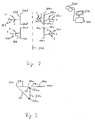
- FIG. 2 shows schematically seen from above the left and right leg of a person lying.
- the left femur is labeled 101
- the left tibia is 201
- the right femur is 10r
- the right tibia is 20r.
- Dashed line is the median sagittal plane 200.
- the right and left leg are symmetrical with respect to this plane.
- marker devices 221, 121, 22r and 12r respectively with markers 1, 2 and 3 which are detected by the detection device 300.
- the tag devices reference templates 221 and 121
- the tag devices are preferably fixedly connected to the femur and tibia.
- the marker devices are preferably non-invasively attached but, for example, wound around the femur and tibia by means of a flexible band Alternatively or additionally, individual markers may be applied to the femur or tibia Headbands known from head surgery may be used.
- reference systems are associated with the femur 101 and 10r and the tibia 201 and 20r.
- this landmark ie the tibial plateau
- a navigation system which detects the markers on the pointer and thus detects the position of the pointer tip, preferably by means of a pointer 30 on a hinge-side landmark, preferably the tibial plateau.
- the anterior-posterior direction is preferably selected during the detection, so that this direction is also detected by the navigation system.
- the pointer 30 be placed halfway up the tibia at the most anterior location to capture that landmark.
- This landmark is then moved by the data processing device of the navigation system in the already detected anterior-posterior direction until a line is cut, which starts from the already detected tibial plateau landmark and perpendicular to the anterior-posterior direction.
- This point of intersection then defines the direction of the tibial axis with the tibial plateau landmark.
- This tibial axis can then form one of the axes of the coordinate system connected to the tibia. For example, the other two axes are perpendicular to it, with one pointing in the anterior-posterior direction, for example.
- 2 shown lines 201 and 20r may be considered as portions of the tibial axis, for example, from the tibial plateau point, for example, coincides with the end point 20ar, and extend over a predetermined length, for example, from a point 20ar to a point 20er, the point 20ar denotes the end facing the joint.
- the position of the end points in the respective tibia reference system is also known.
- the next step is to determine the reference systems of the femur.
- the reference system connected to the tibia is copied and along the tibial axis, in particular by a predetermined length (for example, with reference to the point 20ar or 20al) in the direction of Femur shifted so that the origin of the copied frame of reference lies in the femur.
- the sublime copied reference system then becomes the reference system of the femur.
- the in FIG. 2 shown portions 10r and 101 part of a coordinate axis of the femur reference system, which is part of an elongated tibial axis in extension of the leg.
- a femoral reference system may also be determined by detecting landmarks on the femur.
- the respective axle sections 201, 20r, 10r and 101 are now registered in the reference system of the navigation system.
- the relative position of the axle sections to each other is known and in particular end points 10ar, 10er and 20ar and 20er of the femur section can be determined, for example, it is determined that in the extension state, a predetermined distance between 20ar and 10ar and / or between 20s and 10s consists. It can also be stated that there is a predetermined distance between 10ar and 10per as well as between 20ar and 20er.
- the relative position of the axle sections and also of the end points can be determined by detection of the marker devices 221, 121, 22r and 12r. From this detection signal data, the relative position data for the right and the left side can thus be derived.
- FIG. 3 shows the transition from 0 ° flexion to 90 ° flexion on the right.
- the axial sections for 0 ° flexion (extension) are designated 10r and 20r.
- the shaft sections are labeled 10r and 20'r.
- the relative position between 10r and 20'r is detected by means of marker devices, and the detection signals are for example a data processing device 400 (see FIG. 2 ).
- the relative position between 10r and 20r is already known, as described above. Accordingly, the position of the end points 20'ar and 20'er can be determined. Overall, it is thus possible to determine relative vectors va and ve from the available data.
- the relative vector va points from the end point 20ar to the end point 20'ar.
- the relative vector ve points from the end point 20 to the end point 20'er. This is just one example. Another approach would be to determine, for example, relative vectors from endpoints 10ar to endpoint 20'ar and from endpoint 10s to endpoint 20 's. Furthermore, the change in position could also be described by means of angles, for example over the 90 ° angle and through the plane in which the sections 20r, 20'r and 10r lie. The invention will now be described by way of example with the aid of the abovementioned vectors va and ve.
- the leg in extension ie the position of the leg is described by the sections 101 and 201.
- the aforementioned vectors va and ve already calculated are used.
- the vector va is set at the end point 20al to point to the end point 20'al.
- the vector ve is set at the end point 20el to point to the end point 20'el. This means that it is assumed that the left tibia performs the same relative movement to the left femur as the right tibia relative to the right femur.
- FIG. 5 For example, let's take a look from above at a standing patient who has lifted his right and left arms.
- 501 designates the left upper arm extended in the dorsal direction perpendicular to the median sagittal plane, and 50 r the right upper arm, which extends dorsally perpendicular to the median sagittal plane 200.
- the left forearm 601 is in extension to the left upper arm 501
- the right forearm 60r is in extension to the right upper arm 50r.
- the relative positions 501 to 601 and 50r to 60r are each again detected by means of marker devices, and the axis sections 501 to 601 and 50r to 60r are each in turn detected with pointers, so that they are analogous to those in FIG FIG.
- the parallel part of we is called wep and the vertical part wes.
- the vertical parts are parallel to the frontal plane.
- the relative vector w'e for the left side which is calculated from wep-wes, is determined from the vector we and in particular from the components wes and wep.
- the resulting vector w'e is symmetrical with respect to the vector we with respect to the median sagittal plane.
- a vector w'a is calculated which is symmetric to the vector wa.
- the symmetrical vector w'e is then applied to the end of the shaft portion 601 facing away from the elbow joint, and the relative vector w'a is applied to the end of the shaft portion 601 facing the elbow joint.
- the tips of the two vectors then point to the respective ends of the (90 °) tilted axis portion 601, so that the position of the shaft portion 601 results, the symmetry rules were observed.
- the position of the axle portion 601 thus indicates the position of the left forearm assuming that it is moved symmetrically to the right forearm and thus also bent or pivoted by 90 °. It can thus be determined how the left forearm would lie at 90 ° deflection, if the left elbow joint would have a kinematic symmetry to the right elbow joint and would also behave like a healthy joint.
- the relative position data mentioned above were based in particular on the assumption that they were obtained in neutral position of the respective body parts.
- the extension of the tibia is threaded relative to the femur, allowing a slight play of relative rotation of the tibia relative to the femur.
- this screw connection is not given. This is especially true for the diseased leg (Cruciate ligament tear), which is why the inventive virtual diffraction of the diseased leg is considered advantageous.
- the tibia is rotated relative to the femur in order to determine the second relative position or further relative positions, that is to say the respective neutral position, and the mean value of the two extreme rotation angles (maximum internal rotation and maximum external rotation) is selected as the neutral position.
- the mean value of the two extreme rotation angles maximum internal rotation and maximum external rotation
- a pointer indicates a particular area 20'B (see FIG. 4 ), which is suitable, for example, as a joint-side end of a bore through the tibia, thereby forming a band 100 (see FIG. 1 ) respectively.
- an area 10B (see FIG. 4 ), which, for example, is also near the articular end of the femur.
- the areas 20'B and 10B lie on the respective axle sections. This is purely exemplary. In practice, they may well be outside the axis section.
- An example of the range 20'B is the in FIG. 1 shown area 122. The same was in FIG. 4 noted.
- An example of the area 10B is the area 111 in FIG FIG. 1 ,
- the relative position of the regions 20'B and 10B relative to the coordinate system of the tibia and the femur is known.
- relative positions to the end points 20'al and 20'el as well as 10al and 10el are also known.
- the leg can now be moved virtually virtually.
- the tibia is moved from the position designated 20'1 to the position 201 (see FIG. 4 ).
- other intermediate positions can be taken.
- this results in at least two relative positions for which the relative position between the regions 20'B and 10B can be calculated.
- it can be checked whether the distance for the different relative positions is the same or changes. If the distance changes, this can be displayed and an operator can then, for example, use the pointer procedure to find a new area on the femur, for example, which is also near the joint and which meets the desired condition.
- the position of the left diseased leg is not reliable at 90 ° flexion.
- it can be calculated by detection of the tibia mounted on the marker means, where the tapped with the pointer area would be if the tibia would take a calculated relative position and / or the first first-side relative position. In this way, it can be calculated for each position of the pointer whether the distance between 20'B and 10B is equal to the distance between 20B and 10B without moving the leg. Of course, this can still be calculated for several relative positions. For example, the pointer is brought to various locations 10B, and the navigation system 300, 400, and 500 displays the display 500 if the distance is the same, or e.g. differs by less than a predetermined percentage for the various calculated relative positions.
- the present invention is also suitable for checking the movement and relative positions of a diseased joint by comparison with movements and relative positions of the healthy joint.
- several relative positions for the healthy joint can be detected and stored and from this a sequence of movements can be calculated.
- corresponding (kinematically symmetrical) relative positions and movements for the body side with the diseased joint can then be calculated.
- On the basis of the attached on the sick side marker devices (invasive or non-invasive) can then be checked whether the movement is kinematically symmetrical to the healthy joint or whether a kinematically symmetrical position was taken.
- the movement corresponds to a healthy process.
- cruciate ligament cracks can thus also be detected.
- the axis about which the rotation takes place can also be regarded as the axis of symmetry. If this is determined for both sides, then, for example, an external rotation of the second second-sided joint, such as the right tibia by a certain angle in a certain direction of rotation by applying the symmetry considerations in a corresponding external rotation by the same angle of the second first-sided body part, so for example left tibia are converted in the opposite sense of rotation.
- the axis of symmetry of rotation for example, the already determined tibial axis can be used for the respective side.
- the navigation system according to the invention is also schematically shown in FIG FIG. 2 shown.
- the detection device 300 detects signals from the marker devices 22r, 12r, 101 and 221 and performs the detection signals of the data processing device 400. This performs the method according to the invention and displays display signals on the monitor 500.
- FIG. 5 can also be used as an example of another embodiment of the invention in which the positions of the right and left upper arm and forearm are given and one wishes to determine whether the transition from full extension to 90 ° deflection occurs symmetrically for both sides.
- the vectors we and wa can then be mirrored at the median sagittal plane.
- the mirrored vectors are the vectors w'a and w'e. They describe how the positional relative position on the left side would be if the body is ideally symmetric. So you describe the mirrored from right to left position relational.
- the in FIG. 5 first example body part data are given, which describe the position 601 for the left forearm for the full extension and describe the position 601 for the 90 ° bend.
- the mirrored relative vector w'e is identical to a left side relative vector which connects the end of the axle section 601 to the end of the axle section 60'l.
- the mirrored vector w'a is identical to the vector connecting the beginning of the axis section 601 to the beginning of the axis section 60'l.
- the arrangement shown would be ideally symmetrical with respect to the positional relative position of the forearm from full extension to 90 ° deflection.
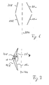
- FIG. 6 shows a case where such ideal symmetry is not given.
- the right and left leg should be in extension.
- the patient has a varying degree of varus.
- the varus on the right side is stronger than on the left side.
- the femur 10r and the tibia 20r are mirrored at the median sagittal plane 200, so that the in FIG. 7 shown situation.
- the mirrored right tibia is marked 20'r and the mirrored right femur is 10'r.
- the left femur is designated 101 and the left tibia is designated 201.
- sections 20'r, 10'r, 101 and 201 are displayed on a monitor in order to give an indication of deviations from an ideal-symmetrical arrangement of the body parts.
- the non-mirrored left body parts differ in their position from the mirrored right body parts.
- This deviation can also be described by relative variables.
- an angle ⁇ between the mirrored sections 20'r and 10'r can be determined.
- a corresponding angle can be determined between the track sections 201 and 101.
- the angular difference then represents a relative quantity which gives an indication of how strong a deviation from the ideal symmetrical arrangement of the body parts is.
- a distance ⁇ may be determined, for example those Endpoints of route 10r and 10'r are connected, which are closest to route 201 and 20'r, respectively. The greater the distance ⁇ , the greater the deviation from the ideal-symmetrical arrangement.
Landscapes
- Health & Medical Sciences (AREA)
- Surgery (AREA)
- Life Sciences & Earth Sciences (AREA)
- Heart & Thoracic Surgery (AREA)
- Molecular Biology (AREA)
- Oral & Maxillofacial Surgery (AREA)
- Engineering & Computer Science (AREA)
- Biomedical Technology (AREA)
- Nuclear Medicine, Radiotherapy & Molecular Imaging (AREA)
- Medical Informatics (AREA)
- Pathology (AREA)
- Animal Behavior & Ethology (AREA)
- General Health & Medical Sciences (AREA)
- Public Health (AREA)
- Veterinary Medicine (AREA)
- Measurement Of The Respiration, Hearing Ability, Form, And Blood Characteristics Of Living Organisms (AREA)
- Apparatus For Radiation Diagnosis (AREA)
Claims (16)
- Procédé pour calculer la position de parties corporelles anatomiquement correspondantes (10, 20) en tenant compte de la symétrie anatomique,
dans lequel une première et une seconde partie corporelle de premier côté (101, 201) sont prévues sur le premier côté d'un corps anatomique et y sont reliées par l'intermédiaire d'une articulation de premier côté,
dans lequel une première et une seconde partie corporelle de second côté (10r, 20r) sont prévues sur le second côté du corps anatomique et y sont reliées par l'intermédiaire d'une articulation de second côté, dans lequel le procédé est mis en oeuvre par un ordinateur et comporte les étapes suivantes consistant à :fournir des données de position relative du second côté qui décrivent la position relative de la première partie corporelle du second côté (10r) par rapport à la seconde partie corporelle du second côté (20r, 20'r) respectivement pour un premier (10r, 20r) et un second (10r, 20'r) placement relatif du second côté,fournir des données de position relative du premier côté qui décrivent la position relative de la première partie corporelle du premier côté (101) par rapport à la seconde partie corporelle du premier côté (201) dans un premier placement relatif du premier côté (101, 201),calculer, sur la base des données de position relative du premier côté et des données de position relative du second côté, la position relative de la première partie corporelle du premier côté (101) par rapport à la seconde partie corporelle du premier côté (20'1) dans un second placement relatif du premier côté (101, 20'1), en tenant compte du fait que le second placement relatif du second côté (10r, 20'r) doit être symétrique au second placement relatif du premier côté et que le premier placement relatif du second côté (10r, 20r) est symétrique au premier placement relatif du premier côté (101, 201). - Procédé selon la revendication 1, dans lequel on calcule le second placement relatif du premier côté en supposant que le premier placement relatif du premier côté (101, 201) est symétrique au premier placement relatif du second côté (10r, 20r) et/ou les données de position relative du premier côté et du second côté incluent les positions des première et seconde parties corporelles du premier côté et du second côté pour les premier et second placements relatifs du second côté et pour le premier placement relatif du premier côté et la position de la première partie corporelle du premier côté dans le second placement relatif du premier côté ainsi que la position d'un plan de symétrie du corps.
- Procédé selon la revendication 1 ou 2, dans lequel on utilise des règles de symétrie pour déterminer le second placement relatif du premier côté (101, 20'1), lesquelles règles tiennent compte de la symétrie du mouvement des parties corporelles du premier côté autour de l'articulation du premier côté par rapport au mouvement des parties corporelles du second côté autour de l'articulation du second côté.
- Procédé selon l'une quelconque des revendications 1 à 3, dans lequel on fournit ou on détermine la position de plans de symétrie (200) et/ou d'axes de symétrie du corps, par rapport auxquels le mouvement de l'articulation est symétrique, dans lequel, sur la base des plans de symétrie (200) et/ou des axes de symétrie déterminés ou fournis, on détermine le second placement relatif du premier côté (101, 20'1) conjointement avec les règles de symétrie, lequel second placement relatif du premier côté est symétrique au second placement relatif du second côté.
- Procédé selon l'une quelconque des revendications 1 à 4, dans lequel on fournit des données de régions qui décrivent la position relative d'une première région (10B) de la première partie corporelle du premier côté par rapport à une seconde région (20B, 20'B) de la seconde partie corporelle du premier côté, dans lequel on calcule une première grandeur relative qui indique la position relative de la première région par rapport à la seconde région, à partir des données de régions pour le premier placement relatif du premier côté (101, 201), et on calcule une seconde grandeur relative à partir des données de régions pour le second placement relatif du premier côté (101, 20'1).
- Procédé selon la revendication 5, dans lequel on calcule les données de régions à partir de la position de la première et/ou seconde région dans un autre placement relatif du premier côté qui correspond au premier placement relatif du premier côté ou au second placement relatif du premier côté, dans lequel on effectue le calcul des premières et/ou secondes données de régions sur la base de la position de la première partie corporelle et/ou de la seconde partie corporelle dans l'autre placement relatif du premier côté par rapport à leur position dans le premier et/ou second placement relatif du premier côté.
- Procédé selon l'une quelconque des revendications 5 ou 6, dans lequel les données de régions varient et la comparaison est effectuée pendant le processus de variation, dans lequel on affiche (500) lorsque les première et seconde grandeurs relatives sont au moins approximativement identiques.
- Procédé selon l'une quelconque des revendications précédentes, dans lequel au moins une partie des données est basée sur la détection (300) de la position des parties corporelles et/ou des régions de manière à fournir des données actuelles, et les calculs sont effectués en utilisant les données actuelles.
- Procédé selon l'une quelconque des revendications précédentes, dans lequel, à partir de la position des parties corporelles du second côté (10r, 20r, 20'r) dans les premier et second placements relatifs du second côté, en particulier également dans d'autres placements relatifs du second côté, on détermine et on mémorise en particulier une trajectoire du second côté et/ou une plage de mouvement du mouvement relatif du second côté de la première partie corporelle du second côté (10r) par rapport à la seconde partie corporelle du second côté (20r, 20'r), et dans lequel on détermine, sur la base de signaux de données qui sont basés sur la détection (300) de la position de la première et de la seconde partie corporelle du premier côté (101, 201, 20'1), si une trajectoire du premier côté et/ou une plage de mouvement du mouvement relatif du premier côté de la partie corporelle du premier côté, déterminée à partir des signaux de données, correspond à la trajectoire du second côté et/ou à la plage de mouvement du second côté au moins sur une étendue prédéterminée, et/ou si la trajectoire du premier côté et/ou la plage de mouvement s'écarte de la trajectoire et/ou de la plage de mouvement du second côté au moins sur une étendue prédéterminée.
- Procédé selon l'une quelconque des revendications précédentes, dans lequel on décrit la position d'une partie corporelle selon au moins une des manières suivantes :par la position d'un axe caractéristique et/ou d'un plan de la partie corporelle,par la position d'un modèle générique représentant la partie corporelle ou d'un corps de base géométrique,par la position de points de repère sur la partie corporelle.
- Programme qui, lorsqu'il tourne sur un ordinateur (400) ou lorsqu'il est chargé sur un ordinateur (400), amène l'ordinateur (400) à mettre en oeuvre un procédé pour calculer la position de parties corporelles anatomiquement correspondantes (10, 20) en tenant compte de la symétrie anatomique,
dans lequel une première et une seconde partie corporelle de premier côté (101, 201) sont prévues sur le premier côté d'un corps anatomique et y sont reliées par l'intermédiaire d'une articulation de premier côté,
dans lequel une première et une seconde partie corporelle de second côté (10r, 20r) sont prévues sur le second côté du corps anatomique et y sont reliées par l'intermédiaire d'une articulation de second côté, dans lequel le procédé comporte les étapes suivantes consistant à :fournir des données de position relative du second côté qui décrivent la position relative de la première partie corporelle du second côté (10r) par rapport à la seconde partie corporelle du second côté (20r, 20'r) respectivement pour un premier (10r, 20r) et un second (10r, 20'r) placement relatif du second côté,fournir des données de position relative du premier côté qui décrivent la position relative de la première partie corporelle du premier côté (101) par rapport à la seconde partie corporelle du premier côté (201) dans un premier placement relatif du premier côté (101, 201),calculer, sur la base des données de position relative du premier côté et des données de position relative du second côté, la position relative de la première partie corporelle du premier côté (101) par rapport à la seconde partie corporelle du premier côté (20'1) dans un second placement relatif du premier côté (101, 20'1), en tenant compte du fait que le second placement relatif du second côté (10r, 20'r) doit être symétrique au second placement relatif du premier côté et que le premier placement relatif du second côté (10r, 20r) est symétrique au premier placement relatif du premier côté (101, 201). - Programme selon la revendication précédente, dans lequel le procédé à mettre en oeuvre inclut de plus les caractéristiques de l'une quelconque des revendications 2 à 10.
- Support de mémorisation sur lequel le programme selon la revendication 11 ou 12 est mémorisé.
- Onde de signal transportant des informations correspondant au programme selon la revendication 11 ou 12.
- Ordinateur (400) sur lequel le programme selon la revendication 11 ou 12 tourne ou est mémorisé.
- Système de navigation comportant :un dispositif de détection (300) qui génère des signaux de détection par la détection de marqueurs (221, 22r, 121, 12r) et/ou d'un pointeur,l'ordinateur (400) selon la revendication 14 qui traite les signaux de détection de manière à acquérir les données requises pour calculer la position de parties corporelles par l'intermédiaire du programme.
Priority Applications (3)
| Application Number | Priority Date | Filing Date | Title |
|---|---|---|---|
| DE502008002604T DE502008002604D1 (de) | 2008-02-21 | 2008-02-21 | Lageberechnung von Körperteilen unter Berücksichtigung der anatomischen Symmetrie |
| EP08151747A EP2092907B1 (fr) | 2008-02-21 | 2008-02-21 | Calcul de la position de parties du corps en fonction de la symétrie anatomique |
| US12/388,711 US8092400B2 (en) | 2008-02-21 | 2009-02-19 | Calculating the position of body parts, taking into account anatomical symmetry |
Applications Claiming Priority (1)
| Application Number | Priority Date | Filing Date | Title |
|---|---|---|---|
| EP08151747A EP2092907B1 (fr) | 2008-02-21 | 2008-02-21 | Calcul de la position de parties du corps en fonction de la symétrie anatomique |
Publications (2)
| Publication Number | Publication Date |
|---|---|
| EP2092907A1 EP2092907A1 (fr) | 2009-08-26 |
| EP2092907B1 true EP2092907B1 (fr) | 2011-02-16 |
Family
ID=39591251
Family Applications (1)
| Application Number | Title | Priority Date | Filing Date |
|---|---|---|---|
| EP08151747A Active EP2092907B1 (fr) | 2008-02-21 | 2008-02-21 | Calcul de la position de parties du corps en fonction de la symétrie anatomique |
Country Status (3)
| Country | Link |
|---|---|
| US (1) | US8092400B2 (fr) |
| EP (1) | EP2092907B1 (fr) |
| DE (1) | DE502008002604D1 (fr) |
Families Citing this family (21)
| Publication number | Priority date | Publication date | Assignee | Title |
|---|---|---|---|---|
| CN106037872B (zh) | 2007-12-06 | 2020-01-07 | 史密夫和内修有限公司 | 用于确定股骨的机械轴线的系统和方法 |
| US8794977B2 (en) * | 2009-04-29 | 2014-08-05 | Lifemodeler, Inc. | Implant training system |
| CA2802190A1 (fr) | 2010-06-11 | 2011-12-15 | Smith & Nephew, Inc. | Instruments adaptes aux patients |
| WO2012024306A2 (fr) * | 2010-08-16 | 2012-02-23 | Aashiish Agnihotri | Guides chirurgicaux |
| WO2012173890A2 (fr) | 2011-06-16 | 2012-12-20 | Smith & Nephew, Inc. | Alignement chirurgical à l'aide de références |
| GB2536650A (en) | 2015-03-24 | 2016-09-28 | Augmedics Ltd | Method and system for combining video-based and optic-based augmented reality in a near eye display |
| US12458411B2 (en) | 2017-12-07 | 2025-11-04 | Augmedics Ltd. | Spinous process clamp |
| US12521201B2 (en) | 2017-12-07 | 2026-01-13 | Augmedics Ltd. | Spinous process clamp |
| WO2019211741A1 (fr) | 2018-05-02 | 2019-11-07 | Augmedics Ltd. | Enregistrement d'un marqueur fiduciel pour un système de réalité augmentée |
| US11766296B2 (en) | 2018-11-26 | 2023-09-26 | Augmedics Ltd. | Tracking system for image-guided surgery |
| US12178666B2 (en) | 2019-07-29 | 2024-12-31 | Augmedics Ltd. | Fiducial marker |
| US11980506B2 (en) | 2019-07-29 | 2024-05-14 | Augmedics Ltd. | Fiducial marker |
| US11382712B2 (en) | 2019-12-22 | 2022-07-12 | Augmedics Ltd. | Mirroring in image guided surgery |
| US11389252B2 (en) | 2020-06-15 | 2022-07-19 | Augmedics Ltd. | Rotating marker for image guided surgery |
| US12239385B2 (en) | 2020-09-09 | 2025-03-04 | Augmedics Ltd. | Universal tool adapter |
| US12502163B2 (en) | 2020-09-09 | 2025-12-23 | Augmedics Ltd. | Universal tool adapter for image-guided surgery |
| US11896445B2 (en) | 2021-07-07 | 2024-02-13 | Augmedics Ltd. | Iliac pin and adapter |
| US12150821B2 (en) | 2021-07-29 | 2024-11-26 | Augmedics Ltd. | Rotating marker and adapter for image-guided surgery |
| WO2023021451A1 (fr) | 2021-08-18 | 2023-02-23 | Augmedics Ltd. | Assistance par réalité augmentée pour ostéotomie et discectomie |
| WO2023203521A1 (fr) | 2022-04-21 | 2023-10-26 | Augmedics Ltd. | Systèmes et procédés de visualisation d'image médicale |
| IL319523A (en) | 2022-09-13 | 2025-05-01 | Augmedics Ltd | Augmented reality glasses for image-guided medical intervention |
Family Cites Families (10)
| Publication number | Priority date | Publication date | Assignee | Title |
|---|---|---|---|---|
| US3879849A (en) * | 1972-10-16 | 1975-04-29 | Robert Schwartz | Orthodontic appliance system |
| FR2699271B1 (fr) | 1992-12-15 | 1995-03-17 | Univ Joseph Fourier | Procédé de détermination du point d'ancrage fémoral d'un ligament croisé de genou. |
| AU755182B2 (en) | 1999-11-15 | 2002-12-05 | Ao Technology Ag | Method and device for the determination of reduction parameters for the subsequent reduction of a fractured bone |
| FR2804596B1 (fr) * | 2000-02-04 | 2002-10-04 | Agronomique Inst Nat Rech | Procede d'analyse d'irregularites de locomotion humaine |
| US7209776B2 (en) * | 2002-12-03 | 2007-04-24 | Aesculap Ag & Co. Kg | Method of determining the position of the articular point of a joint |
| US7503900B2 (en) * | 2003-07-03 | 2009-03-17 | Honda Motor Co., Ltd. | Kinematic quantification of gait asymmetry based on bilateral cyclograms |
| FR2880791B1 (fr) | 2005-01-18 | 2007-04-06 | Perception Raisonnement Action | Procede et dispositif d'assistance par ordinateur pour la reduction d'une fracture |
| US7925324B2 (en) * | 2005-11-16 | 2011-04-12 | Brainlab Ag | Measuring the femoral antetorsion angle γ of a human femur in particular on the basis of fluoroscopic images |
| US7362248B2 (en) | 2005-11-22 | 2008-04-22 | Stmicroelectronics, Inc. | Temperature tamper detection circuit and method |
| US20070179626A1 (en) | 2005-11-30 | 2007-08-02 | De La Barrera Jose L M | Functional joint arthroplasty method |
-
2008
- 2008-02-21 EP EP08151747A patent/EP2092907B1/fr active Active
- 2008-02-21 DE DE502008002604T patent/DE502008002604D1/de active Active
-
2009
- 2009-02-19 US US12/388,711 patent/US8092400B2/en active Active
Also Published As
| Publication number | Publication date |
|---|---|
| US20090227905A1 (en) | 2009-09-10 |
| EP2092907A1 (fr) | 2009-08-26 |
| DE502008002604D1 (de) | 2011-03-31 |
| US8092400B2 (en) | 2012-01-10 |
Similar Documents
| Publication | Publication Date | Title |
|---|---|---|
| EP2092907A1 (fr) | Calcul de la position de parties du corps en fonction de la symétrie anatomique | |
| DE102006056399B4 (de) | Funktionsgelenk-Arthroplastikverfahren | |
| DE69424416T2 (de) | Vorrichtung zur lokalisierung funktioneller strukturen des beins während der kniegelenkschirurgie | |
| EP1591075B1 (fr) | Procédé et dispositif pour la préparation d'un implant de genou | |
| DE60312210T2 (de) | Verfahren zur bestimmung der gelenkdrehmittelpunkte | |
| DE60215561T2 (de) | Rechnerunterstütztes System für Kniegelenkrekonstruktion | |
| DE102004052228B4 (de) | System und Verfahren zum Ausrichten von Bilddaten bezüglich intraoperativ digitalisierter Charakteristika | |
| EP0969780B1 (fr) | Procede et dispositif de determination preoperatoire de donnees de positionnement de parties d'endoprotheses | |
| EP1955668B1 (fr) | Procédé et dispositif pour la détermination des informations d'alignement pendant le repositionnement navigué sonographiquement de fragments d'os | |
| DE112005002453B4 (de) | System und Verfahren zum Durchführen einer Arthroplastik eines Gelenks und zum Verfolgen einer senkrechten Ebene | |
| EP1932495B1 (fr) | Détermination de l'orientation d'une articulation pour une implantation | |
| EP1402855B1 (fr) | Appareil et méthode pour déterminer le débattement d'une articulation | |
| EP1507472B1 (fr) | Dispositif de fixation intra-operatoire de l'emplacement d'un implant d'articulation artificielle | |
| DE102011106812A1 (de) | Registrierung von anatomischen Datensätzen | |
| EP3393391A1 (fr) | Dispositif de navigation intra-opératoire guidée par l'image lors d'opérations chirurgicales dans la région de la colonne vertébrale et dans la région adjacente du thorax, du bassin ou de la tête | |
| DE112007002138T5 (de) | Nicht invasive Nachverfolgungseinrichtung und nicht invasives Nachverfolgungsverfahren | |
| EP2555702A1 (fr) | Procédé non invasif et dispositif pour déterminer un plan de référence du bassin humain | |
| DE112006002688T5 (de) | System und Verfahren zur Knochenresektion | |
| WO2023218039A1 (fr) | Dispositif et méthode de normalisation de l'orientation axiale et de la position de données cinématiques par rapport à une articulation corporelle d'un patient | |
| EP2164393A2 (fr) | Procédé de détermination d'informations importantes pour la caractérisation de mouvements articulaires | |
| EP4384103B1 (fr) | Système et méthode de planification préopératoire d'une endoprothèse du genou | |
| DE102007031946A1 (de) | Verfahren zum Ermitteln von für die Charakterisierung von Gelenkbewegungen relevanten Informationen | |
| WO2006074954A1 (fr) | Procede pour determiner la position neutre d'un femur par rapport a un os iliaque et systeme pour mettre en oeuvre ce procede | |
| DE102021124873A1 (de) | Medizintechnisches System und Verfahren | |
| DE102009034669B4 (de) | Verfahren zum Erzeugen eines Durchleuchtungsbildes einer zu reponierenden Extremität |
Legal Events
| Date | Code | Title | Description |
|---|---|---|---|
| PUAI | Public reference made under article 153(3) epc to a published international application that has entered the european phase |
Free format text: ORIGINAL CODE: 0009012 |
|
| 17P | Request for examination filed |
Effective date: 20080221 |
|
| AK | Designated contracting states |
Kind code of ref document: A1 Designated state(s): AT BE BG CH CY CZ DE DK EE ES FI FR GB GR HR HU IE IS IT LI LT LU LV MC MT NL NO PL PT RO SE SI SK TR |
|
| AX | Request for extension of the european patent |
Extension state: AL BA MK RS |
|
| AKX | Designation fees paid |
Designated state(s): DE FR GB |
|
| GRAP | Despatch of communication of intention to grant a patent |
Free format text: ORIGINAL CODE: EPIDOSNIGR1 |
|
| GRAJ | Information related to disapproval of communication of intention to grant by the applicant or resumption of examination proceedings by the epo deleted |
Free format text: ORIGINAL CODE: EPIDOSDIGR1 |
|
| GRAP | Despatch of communication of intention to grant a patent |
Free format text: ORIGINAL CODE: EPIDOSNIGR1 |
|
| GRAS | Grant fee paid |
Free format text: ORIGINAL CODE: EPIDOSNIGR3 |
|
| GRAA | (expected) grant |
Free format text: ORIGINAL CODE: 0009210 |
|
| AK | Designated contracting states |
Kind code of ref document: B1 Designated state(s): DE FR GB |
|
| REG | Reference to a national code |
Ref country code: GB Ref legal event code: FG4D Free format text: NOT ENGLISH |
|
| REF | Corresponds to: |
Ref document number: 502008002604 Country of ref document: DE Date of ref document: 20110331 Kind code of ref document: P |
|
| REG | Reference to a national code |
Ref country code: DE Ref legal event code: R096 Ref document number: 502008002604 Country of ref document: DE Effective date: 20110331 |
|
| PLBE | No opposition filed within time limit |
Free format text: ORIGINAL CODE: 0009261 |
|
| STAA | Information on the status of an ep patent application or granted ep patent |
Free format text: STATUS: NO OPPOSITION FILED WITHIN TIME LIMIT |
|
| 26N | No opposition filed |
Effective date: 20111117 |
|
| REG | Reference to a national code |
Ref country code: DE Ref legal event code: R097 Ref document number: 502008002604 Country of ref document: DE Effective date: 20111117 |
|
| REG | Reference to a national code |
Ref country code: DE Ref legal event code: R082 Ref document number: 502008002604 Country of ref document: DE Representative=s name: SCHWABE SANDMAIR MARX, DE |
|
| REG | Reference to a national code |
Ref country code: DE Ref legal event code: R082 Ref document number: 502008002604 Country of ref document: DE Representative=s name: SCHWABE SANDMAIR MARX, DE Effective date: 20131104 Ref country code: DE Ref legal event code: R081 Ref document number: 502008002604 Country of ref document: DE Owner name: BRAINLAB AG, DE Free format text: FORMER OWNER: BRAINLAB AG, 85622 FELDKIRCHEN, DE Effective date: 20131104 Ref country code: DE Ref legal event code: R082 Ref document number: 502008002604 Country of ref document: DE Representative=s name: SCHWABE SANDMAIR MARX PATENTANWAELTE RECHTSANW, DE Effective date: 20131104 |
|
| REG | Reference to a national code |
Ref country code: FR Ref legal event code: PLFP Year of fee payment: 9 |
|
| REG | Reference to a national code |
Ref country code: FR Ref legal event code: PLFP Year of fee payment: 10 |
|
| REG | Reference to a national code |
Ref country code: DE Ref legal event code: R082 Ref document number: 502008002604 Country of ref document: DE Representative=s name: SCHWABE SANDMAIR MARX PATENTANWAELTE RECHTSANW, DE Ref country code: DE Ref legal event code: R081 Ref document number: 502008002604 Country of ref document: DE Owner name: BRAINLAB AG, DE Free format text: FORMER OWNER: BRAINLAB AG, 85622 FELDKIRCHEN, DE Ref country code: DE Ref legal event code: R082 Ref document number: 502008002604 Country of ref document: DE Representative=s name: SSM SANDMAIR PATENTANWAELTE RECHTSANWALT PARTN, DE |
|
| REG | Reference to a national code |
Ref country code: FR Ref legal event code: CA Effective date: 20170706 |
|
| REG | Reference to a national code |
Ref country code: FR Ref legal event code: PLFP Year of fee payment: 11 |
|
| P01 | Opt-out of the competence of the unified patent court (upc) registered |
Effective date: 20230509 |
|
| REG | Reference to a national code |
Ref country code: DE Ref legal event code: R081 Ref document number: 502008002604 Country of ref document: DE Owner name: BRAINLAB SE, DE Free format text: FORMER OWNER: BRAINLAB AG, 81829 MUENCHEN, DE |
|
| PGFP | Annual fee paid to national office [announced via postgrant information from national office to epo] |
Ref country code: GB Payment date: 20260219 Year of fee payment: 19 |
|
| PGFP | Annual fee paid to national office [announced via postgrant information from national office to epo] |
Ref country code: DE Payment date: 20260218 Year of fee payment: 19 |
|
| PGFP | Annual fee paid to national office [announced via postgrant information from national office to epo] |
Ref country code: FR Payment date: 20260218 Year of fee payment: 19 |