EP2092950A2 - Dreiweghahn und Flüssigkeitstransfusionsschlauchset oder Bluttransfusionsschlauchset mit dem Dreiweghahn - Google Patents
Dreiweghahn und Flüssigkeitstransfusionsschlauchset oder Bluttransfusionsschlauchset mit dem Dreiweghahn Download PDFInfo
- Publication number
- EP2092950A2 EP2092950A2 EP09006490A EP09006490A EP2092950A2 EP 2092950 A2 EP2092950 A2 EP 2092950A2 EP 09006490 A EP09006490 A EP 09006490A EP 09006490 A EP09006490 A EP 09006490A EP 2092950 A2 EP2092950 A2 EP 2092950A2
- Authority
- EP
- European Patent Office
- Prior art keywords
- flow passage
- opening
- branch
- way stopcock
- fluid flow
- Prior art date
- Legal status (The legal status is an assumption and is not a legal conclusion. Google has not performed a legal analysis and makes no representation as to the accuracy of the status listed.)
- Withdrawn
Links
- 239000008280 blood Substances 0.000 title claims description 8
- 210000004369 blood Anatomy 0.000 title claims description 8
- 239000007788 liquid Substances 0.000 title claims description 7
- 239000012530 fluid Substances 0.000 claims abstract description 127
- 238000004891 communication Methods 0.000 claims abstract description 16
- 238000002347 injection Methods 0.000 claims description 19
- 239000007924 injection Substances 0.000 claims description 19
- 238000003780 insertion Methods 0.000 claims description 5
- 230000037431 insertion Effects 0.000 claims description 5
- 230000002093 peripheral effect Effects 0.000 claims description 4
- 239000000203 mixture Substances 0.000 description 5
- 230000000694 effects Effects 0.000 description 4
- 238000000034 method Methods 0.000 description 4
- 230000037452 priming Effects 0.000 description 4
- 239000012535 impurity Substances 0.000 description 3
- 241000894006 Bacteria Species 0.000 description 2
- 238000002474 experimental method Methods 0.000 description 2
- 229920000515 polycarbonate Polymers 0.000 description 2
- 239000004417 polycarbonate Substances 0.000 description 2
- 229920000178 Acrylic resin Polymers 0.000 description 1
- 239000004925 Acrylic resin Substances 0.000 description 1
- 229930182556 Polyacetal Natural products 0.000 description 1
- 239000004743 Polypropylene Substances 0.000 description 1
- 239000000956 alloy Substances 0.000 description 1
- 229910045601 alloy Inorganic materials 0.000 description 1
- 238000009395 breeding Methods 0.000 description 1
- 230000001488 breeding effect Effects 0.000 description 1
- 238000007796 conventional method Methods 0.000 description 1
- 230000003247 decreasing effect Effects 0.000 description 1
- 230000002401 inhibitory effect Effects 0.000 description 1
- 238000004519 manufacturing process Methods 0.000 description 1
- 239000000463 material Substances 0.000 description 1
- 239000002184 metal Substances 0.000 description 1
- 229920006324 polyoxymethylene Polymers 0.000 description 1
- -1 polypropylene Polymers 0.000 description 1
- 229920001155 polypropylene Polymers 0.000 description 1
Images






Classifications
-
- A—HUMAN NECESSITIES
- A61—MEDICAL OR VETERINARY SCIENCE; HYGIENE
- A61M—DEVICES FOR INTRODUCING MEDIA INTO, OR ONTO, THE BODY; DEVICES FOR TRANSDUCING BODY MEDIA OR FOR TAKING MEDIA FROM THE BODY; DEVICES FOR PRODUCING OR ENDING SLEEP OR STUPOR
- A61M39/00—Tubes, tube connectors, tube couplings, valves, access sites or the like, specially adapted for medical use
-
- A—HUMAN NECESSITIES
- A61—MEDICAL OR VETERINARY SCIENCE; HYGIENE
- A61M—DEVICES FOR INTRODUCING MEDIA INTO, OR ONTO, THE BODY; DEVICES FOR TRANSDUCING BODY MEDIA OR FOR TAKING MEDIA FROM THE BODY; DEVICES FOR PRODUCING OR ENDING SLEEP OR STUPOR
- A61M39/00—Tubes, tube connectors, tube couplings, valves, access sites or the like, specially adapted for medical use
- A61M39/22—Valves or arrangement of valves
- A61M39/223—Multiway valves
-
- Y—GENERAL TAGGING OF NEW TECHNOLOGICAL DEVELOPMENTS; GENERAL TAGGING OF CROSS-SECTIONAL TECHNOLOGIES SPANNING OVER SEVERAL SECTIONS OF THE IPC; TECHNICAL SUBJECTS COVERED BY FORMER USPC CROSS-REFERENCE ART COLLECTIONS [XRACs] AND DIGESTS
- Y10—TECHNICAL SUBJECTS COVERED BY FORMER USPC
- Y10T—TECHNICAL SUBJECTS COVERED BY FORMER US CLASSIFICATION
- Y10T137/00—Fluid handling
- Y10T137/8593—Systems
- Y10T137/86493—Multi-way valve unit
Definitions
- the present invention relates to a three-way stopcock capable of changing the route of a fluid flow passage by performing a rotational operation of a flow passage switching portion provided in a body having three branch openings so as to allow the communication between predetermined branch openings out of the three branch openings, and relates to a liquid transfusion tubing set or a blood transfusion tubing set using the same.
- a three-way stopcock is used for carrying out mixture injection of different types of medical fluid and for taking a fluid flowing through a fluid flow passage.
- Fig. 9 shows an overall perspective view of a conventional three-way stopcock, in which the conventional three-way stopcock is configured with: a body 1 provided with branch pipes that are connected to three branch openings and in which a fluid can flow; and a flow passage switching portion 5.
- the conventional three-way stopcock is configured in a manner that a rotational operation of a handle 7 configured integrally with the flow passage switching portion 5 allows the selection of a combination of a branch pipe into which a medical fluid flows and a branch pipe communicating with the branch pipe so that the medical fluid flows out of there.
- a first branch pipe 31 and a second branch pipe 32 are arranged so as to assume a straight-line flow passage form when they communicate with each other.
- This flow passage is designated as a main line.
- a branch pipe that is arranged perpendicularly to the main line is a third branch pipe 33, through which mixture injection of medical fluids is carried out and a fluid is taken.
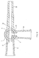
- Fig. 10 is a transverse sectional view of the conventional three-way stopcock. As shown in Fig. 10 , the body 1 is provided with the three branch openings 21, 22 and 23 so as to allow the selectable combination of the first branch pipe 31, the second branch pipe 32 and the third branch pipe 33.
- Fig. 11 schematically shows the direction of a flow passage in the flow passage switching portion of the conventional three-way stopcock.
- the flow passage switching portion 5 is provided with three flow passage openings 61, 62 and 63.
- a fluid flow passage 8 provided in the flow passage switching portion 5 is configured with a flow passage through which the first flow passage opening 61 and the second flow passage opening 62 communicate with each other in a straight line and a flow passage that is arranged so as to branch perpendicularly from the center of this flow passage so as to communicate with the third flow passage opening 63.
- the fluid flow passage 8 is configured in the shape of a T.
- the third branch pipe 33 might be opened to the outside during the mixture injection, resulting in the possibility that bacteria get into there. That is to say, as the third branch pipe 33 has a hollow and long-size pipe structure and it is difficult to disinfect the long-size bore of the pipe, there is the risk that the bore in the third branch pipe 33 becomes a breeding ground for bacteria.
- the flow passage switching portion 5 is configured, as shown in Fig. 10 , in the shape of a T with a portion branching partway, there is the risk that the flow of the main line does not affect the portion X in the flow passage that communicates with the third flow passage opening 63, resulting in the generation of a stagnated portion. Due to the presence of the stagnated portion, a medical fluid to be given might remain there, which causes a problem that it becomes difficult to administer the medical fluid precisely.
- a specially designed blunt needle is used instead of a sharp metal needle.
- JP 11(1999)-342209 A various three-way stopcocks have been developed, as disclosed in JP 11(1999)-342209 A , in which a septum of an elastic member having a slit through which a blunt needle can be punctured is provided at a position corresponding to the third branch pipe for the purpose of eliminating the stagnated portion in the third branch pipe 33.
- the three-way stopcock disclosed in JP 11(1999)-342209 A is a medical stopcock having a feature in which an arcuate groove-like switching passage is formed along the circumferential surface at the switching portion of the flow passage.
- the septum of an elastic member having the slit is disposed at the position corresponding to the third branch pipe 33, so that the branch pipe is isolated from the outside so as to secure a closed system and at the same time the length of the flow passage can be shortened relative to the conventional one.
- the arcuate groove-like switching passage along the circumferential surface at the switching portion of the flow passage, a flow of the fluid is generated also at the portion conventionally acting as the stagnated portion, so as to eliminate the stagnated portion.
- the fluid switching portion 5 when all of the flow passages are closed, the fluid switching portion 5 should be rotated by about 135° to 225°.
- this flow passage switching portion 5 has an arcuate groove form along the circumferential surface, which means the opening portion is open to a large degree.
- complicated operations should be done securely in a short time, and therefore the three-way stopcock having such a configuration has the possibility of operating errors occurring during the use thereof.
- an object of the present invention is to provide a three-way stopcock that can reduce a stagnated portion of a fluid in a fluid flow passage and can be opened/closed in the same manner as the conventional operation methods.
- a three-way stopcock according to the present invention is defined as in claim 1.
- the three flow passage openings are provided so as to be open to the flow passage switching portion, and the two fluid flow passages connecting the respective flow passage openings are formed to be capable of communicating with each other. Therefore, the flow of a fluid can reach a space in the branch opening also, and by performing the priming or the like, a stagnated portion of the fluid can be eliminated.
- the opening portions of the flow passage switching portion are only the three flow passage openings. Therefore by adjusting the portions of the flow passage switching portion having none of the three flow passage openings to the positions of the respective branch openings of the body, the state where the flow passage openings do not communicate with the respective branch openings can be realized. Accordingly, the same operation method as in the conventional three-way stopcocks can be realized.
- the third flow passage opening is formed with two flow passage openings, one of which communicates with the first flow passage opening and the other of which communicates with the second flow passage opening, and at a side wall portion where the two flow passage openings are formed in the third flow passage opening, a groove portion is provided so as to allow communication between the two fluid flow passages. Even in the case where a space is not formed in the branch opening due to a difference in the type of the injection port, a stagnated portion of the fluid can be eliminated by conducting the priming or the like.
- the two flow passage openings in the third flow passage opening are provided to be arranged in a vertical direction of the body. This configuration can reduce the degree of the shift in an angular position when making the portions of the flow passage switching portion having none of the three flow passage openings face the respective branch openings of the body.
- an injection port is provided at a side wall portion that forms the third branch opening. Furthermore, it is preferable that the injection port is capable of being inserted with an insertion member having a blunt tip and is capable of maintaining liquid-tightness.
- a ratio of a cross-sectional area of the fluid flow passages with respect to a cross-sectional area of the third branch opening is 1:49 or more. Furthermore, it is preferable that a ratio of a cross-sectional area of the fluid flow passages with respect to a cross-sectional area of the third branch opening is 1:12.25 or more. In the case of the ratio being smaller than 1:49, the diameter of the fluid flow passages becomes too small to pass a fluid having a relatively high fluid viscosity, such as blood, which is unusable for practical applications. In the case of the ratio being 1:12.25 or more, it was confirmed by an experiment that a stagnated portion does not occur after the priming.
- a "vertical direction” used in the three-way stopcocks described in this specification is defined as a positional relationship of the three-way stopcock assuming that a handle provided in the flow passage switching portion is set at the uppermost part and other end portions are set at the lowermost part, that is, as a direction in a rotational axis of the flow passage switching portion.
- a “horizontal direction” is defined as a positional relationship in the direction perpendicular to the "vertical direction”.
- Fig. 1 is a perspective view of a three-way stopcock according to an embodiment of the present invention.
- the three-way stopcock according to the embodiment of the present invention is configured with a substantially cylindrical-shaped body 11 having three branch openings on the periphery thereof and a flow passage switching portion.
- the flow passage switching portion is mounted so as to be rotatable relative to the body 11 and provide fluid-tightness, has three flow passage openings that form a fluid flow passage so as to allow the communication between predetermined branch openings out of the respective branch openings of the body 11 and is configured integrally with a handle 17.
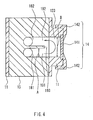
- Fig. 2 is a transverse sectional view of the three-way stopcock according to the embodiment of the present invention.
- the three branch openings 121, 122 and 123 are formed in the body 11, the three branch openings 121, 122 and 123 are formed.
- the first branch opening 121 and the second branch opening 122 are formed at opposed positions on the periphery of the body 11, and the third branch opening 123 is on the periphery of the body 11 and at a position that equally divides the angle between the first branch opening 121 and the second branch opening 122 into 90°.
- a first branch pipe 131 and a second branch pipe 132 respectively are connected to the first branch opening 121 and the second branch opening 122 so as to introduce a fluid into/from there.
- an injection port 14 is connected to the third branch opening 123.
- the injection port 14 is provided with a septum 141 through which a needle or the like can be punctured and is provided for isolating a fluid flow passage 18 in the three-way stopcock from the outside.
- the injection port 14 is configured in a manner that the septum 141 is fixed by a cover 142 so that an insertion portion only is exposed. With this configuration, a closed system to the outside can be formed securely in the fluid flow passage 18 within the three-way stopcock.
- the septum 141 may have a configuration capable of being punctured with a needle or the like and of maintaining a closed system of the fluid flow passage after removing the needle.
- the septum 141 may have a configuration provided with a slit beforehand so as to facilitate the puncturing of a needle or the like and ensure liquid-tightness.
- the septum 141 may have a configuration through which an insertion member having a blunt tip such as a luer can be inserted and so as to ensure liquid-tightness.
- Fig. 3 schematically shows the direction of a flow passage in the flow passage switching portion 15 of the three-way stopcock according to the embodiment of the present invention.
- the arrow indicates the direction of a flow of the fluid.
- the first flow passage opening 161 and the second flow passage opening 162 are formed at opposed positions on the periphery of the flow passage switching portion 15, and the third flow passage opening 163 is on the periphery of the flow passage switching portion 15 and at a position that equally divides the angle between the first flow passage opening 161 and the second flow passage opening 162 into 90°.
- the fluid flow passage 18 provided in the flow passage switching portion 15 is configured with a first fluid flow passage 181 establishing the communication between the first flow passage opening 161 and the third flow passage opening 163 and a second fluid flow passage 182 establishing the communication between the second flow passage opening 162 and the third flow passage opening 163. Furthermore, the first fluid flow passage 181 and the second fluid flow passage 182 are provided so as to communicate with each other in the vicinity of the third flow passage opening 163.
- various means can be considered.
- it can be considered as an effective means to provide a groove portion 193 (the diagonally shaded area in Fig. 3 ) between a base portion 191 of the first fluid flow passage 181 and a base portion 192 of the second fluid flow passage 182 within the third flow passage opening 163.
- the base portions 191 and 192 of the first fluid flow passage 181 and the second fluid flow passage 182 are provided at the third flow passage opening 163 so that the base portion 191 of the first fluid flow passage 181 establishing the communication between the first flow passage opening 161 and the third flow passage opening 163 is located on the lower side and the base portion 192 of the second fluid flow passage 182 establishing the communication between the second flow passage opening 162 and the third flow passage opening 163 is located on the upper side in the vertical direction of the body 11 of the three-way stopcock.
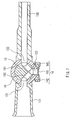
- Fig. 4 is a vertical sectional view of the state in which the flow passage switching portion 15 is rotated so that this third flow passage opening 163 coincides with the third branch opening 123 provided with the injection port 14 having the septum 141.
- a fluid introduced from the first fluid flow passage 181 changes its direction at the third branch opening 123 by passing through a space formed by the groove portion 193 and the third branch opening 123, so as to flow toward the second fluid flow passage 182 located on the upper side.
- the fluid flows while circulating through the space formed in the third branch opening 123 in the body 11, thus preventing that space from acting as a stagnated portion of the fluid.
- the cross-sectional area A of the first fluid flow passage 181 and the second fluid flow passage 182 satisfies an area ratio of 1:49 or more with respect to the cross-sectional area B in the third branch opening 123.
- first fluid flow passage 181 and the second fluid flow passage 182 have the base portions 191 and 192, respectively, facing at the third flow passage opening 163, extend toward the center of the flow passage switching portion 15 while keeping the respective vertical positional relationship, and are bent at the center so as to extend toward the first flow passage opening 161 and the second flow passage opening 162, respectively.
- the fluid flow passage in the flow passage switching portion 15 establishes the communication from the first flow passage opening 161 to the third flow passage opening 163 and the communication from the third flow passage opening 163 to the second flow passage opening 162, and is open at only three positions including the first flow passage opening 161, the second flow passage opening 162 and the third flow passage opening 163, which are the same as the opening positions of the flow passage switching portion in the conventional three-way stopcock.
- the peripheral portions of the flow passage switching portion 15 having no flow passage opening are adjusted to face the respective branch openings of the body 11.
- the base portion 191 of the first fluid flow passage 181 communicating with the first flow passage opening 161 and the base portion 192 of the second fluid flow passage 182 communicating with the second flow passage opening 162 are provided so as to have the vertical positional relationship in the vertical direction of the body 11, which means that the two fluid flow passages communicate with each other in the vertical direction at the third flow passage opening 163.
- the positions where the base portion 191 and the base portion 192 are arranged are not limited to this, and, for example, they may be provided horizontally in the lateral direction of the body 11.
- the structure where the two fluid flow passages communicate with each other in the vertical direction at the third flow passage opening 163 makes it possible to shorten the length (length in the horizontal direction) of the third flow passage opening 163 along the periphery of the flow passage switching portion 15 as compared with the case of the two fluid flow passages communicating in the horizontal direction. Accordingly, the opening portion along the periphery of the flow passage switching portion 15 can be made smaller, so that a larger area on the periphery of the flow passage switching portion 15 having no opening portion can be kept, which enables the closing of all of the flow passages without significantly rotating the flow passage switching portion 15 with respect to the body 11 so as not to allow the flow passage openings communicate with the respective branch openings. That is to say, by adjusting the portions on the flow passage switching portion 15 having none of the three flow passage openings to the positions of the respective branch openings of the body 11, all of the branch openings can be closed.
- the flow passage switching portion 15 In order to change the communicating state into the not-communicating state (closed state), the flow passage switching portion 15 has to be rotated. If a number of opening portions arranged in the horizontal direction is large, then a larger amount of shift in the angular position will be required. On the other hand, if a number of opening portions in the horizontal direction is small, then the change into the not-communicating state (closed state) can be conducted by a very small amount of shift in the angular position.
- the configuration of the fluid flow passage in the flow passage switching portion 15 is not limited to the above-stated configuration.
- one possible configuration is that a first fluid flow passage 181 and a second fluid flow passage 182 having base portions 191 and 192, respectively, at a third flow passage opening 163 extend in a straight line toward a first flow passage opening 161 and a second flow passage opening 162, respectively, from the third flow passage opening 163.
- first fluid flow passage 181 and the second fluid flow passage 182 are provided so that they can communicate with each other in the vicinity of the third flow passage opening 163.
- a means for allowing the communication between the first fluid flow passage 181 and the second fluid flow passage 182 possible one is to provide a groove portion 193 (the diagonally shaded area in Fig. 6 ) between the base portion 191 of the first fluid flow passage 181 and the base portion 192 of the second fluid flow passage 182 within the third flow passage opening 163 in the same manner as in Fig. 3 .
- Fig. 7 is a transverse sectional view of the flow passage switching portion 15 of Fig. 6 , where a fluid flow passage formed within the flow passage switching portion 15 constitutes one fluid flow passage that flows from the first flow passage opening 161 to the second flow passage opening 162 through the third flow passage opening 163.
- the openings of the flow passage switching portion 15 include only the first flow passage opening 161, the second flow passage opening 162 and the third flow passage opening 163 in the same manner as in the above-described embodiment, which is the same configuration of the openings of the flow passage switching portion of the conventional three-way stopcock, and therefore the same effects can be expected.
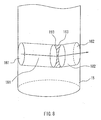
- FIG. 8 another configuration is such that a size of a third opening 163 is made equal to that of a first opening 161 and a second opening 162, and a first fluid flow passage 181 and a second fluid flow passage 182 extend in a straight line from a third flow passage opening 163 to the first flow passage opening 161 and the second flow passage opening 162, respectively.
- first fluid flow passage 181 and the second fluid flow passage 182 are provided so that they can communicate with each other in the vicinity of the third flow passage opening 163.
- a means for allowing the communication between the first fluid flow passage 181 and the second fluid flow passage 182 possible one is to provide a groove portion 193 (the diagonally shaded area in Fig. 8 ) between the base portion 191 of the first fluid flow passage 181 and the base portion 192 of the second fluid flow passage 182 within the third flow passage opening 163 in the same manner as in Fig. 3 .
- the openings of the flow passage switching portion 15 include only the first flow passage opening 161, the second flow passage opening 162 and the third flow passage opening 163 in the same manner as in the above-described embodiment, which is the same configuration of the openings of the flow passage switching portion of the conventional three-way stopcock, and therefore the same effects can be expected.
- the two fluid flow passages communicate at the third flow passage opening 163, there is no need to consider that the base portions of the fluid flow passages are positioned in the vertical direction or in the horizontal direction, and the like. Therefore, the opening portions on the periphery of the flow passage switching portion 15 can be reduced to the minimum. Therefore, in order to close all of the flow passages, the state where the flow passage openings do not communicate with the respective branch openings can be achieved without significantly rotating the flow passage switching portion 15 with respect to the body 11.
- the fluid flow passages in the flow passage switching portion of the three-way stopcock are provided so as to communicate with each other at the injection port, the fluid flows so as to circulate through a space formed in the branch opening of the body, and therefore a stagnated portion does not occur in the space within the body. Thereby, a stagnated portion of the fluid can be eliminated in the three-way stopcock.
- the respective openings can be provided at the similar positions to the conventional three-way stopcock, and therefore the three-way stopcock can be opened/closed in the same manner as in the conventional one. As a result, operating errors by medical staffs can be prevented before they happen.
Landscapes
- Health & Medical Sciences (AREA)
- Heart & Thoracic Surgery (AREA)
- Pulmonology (AREA)
- Engineering & Computer Science (AREA)
- Anesthesiology (AREA)
- Biomedical Technology (AREA)
- Hematology (AREA)
- Life Sciences & Earth Sciences (AREA)
- Animal Behavior & Ethology (AREA)
- General Health & Medical Sciences (AREA)
- Public Health (AREA)
- Veterinary Medicine (AREA)
- Infusion, Injection, And Reservoir Apparatuses (AREA)
- Multiple-Way Valves (AREA)
Applications Claiming Priority (2)
| Application Number | Priority Date | Filing Date | Title |
|---|---|---|---|
| JP2001348142 | 2001-11-14 | ||
| EP02780067A EP1459783A4 (de) | 2001-11-14 | 2002-11-11 | Dreiwege-hahn und flüssigkeitstransfusionskreislauf oder bluttransfusionskreislauf unter verwendung des dreiwege-hahns |
Related Parent Applications (1)
| Application Number | Title | Priority Date | Filing Date |
|---|---|---|---|
| EP02780067A Division EP1459783A4 (de) | 2001-11-14 | 2002-11-11 | Dreiwege-hahn und flüssigkeitstransfusionskreislauf oder bluttransfusionskreislauf unter verwendung des dreiwege-hahns |
Publications (2)
| Publication Number | Publication Date |
|---|---|
| EP2092950A2 true EP2092950A2 (de) | 2009-08-26 |
| EP2092950A3 EP2092950A3 (de) | 2009-09-02 |
Family
ID=19161015
Family Applications (2)
| Application Number | Title | Priority Date | Filing Date |
|---|---|---|---|
| EP02780067A Withdrawn EP1459783A4 (de) | 2001-11-14 | 2002-11-11 | Dreiwege-hahn und flüssigkeitstransfusionskreislauf oder bluttransfusionskreislauf unter verwendung des dreiwege-hahns |
| EP09006490A Withdrawn EP2092950A3 (de) | 2001-11-14 | 2002-11-11 | Dreiweghahn und Flüssigkeitstransfusionsschlauchset oder Bluttransfusionsschlauchset mit dem Dreiweghahn |
Family Applications Before (1)
| Application Number | Title | Priority Date | Filing Date |
|---|---|---|---|
| EP02780067A Withdrawn EP1459783A4 (de) | 2001-11-14 | 2002-11-11 | Dreiwege-hahn und flüssigkeitstransfusionskreislauf oder bluttransfusionskreislauf unter verwendung des dreiwege-hahns |
Country Status (8)
| Country | Link |
|---|---|
| US (1) | US7695445B2 (de) |
| EP (2) | EP1459783A4 (de) |
| JP (1) | JP3945480B2 (de) |
| KR (1) | KR100731429B1 (de) |
| CN (1) | CN1332722C (de) |
| AU (1) | AU2002344492B2 (de) |
| CA (1) | CA2467066C (de) |
| WO (1) | WO2003041788A1 (de) |
Families Citing this family (85)
| Publication number | Priority date | Publication date | Assignee | Title |
|---|---|---|---|---|
| IL114960A0 (en) | 1995-03-20 | 1995-12-08 | Medimop Medical Projects Ltd | Flow control device |
| IL161660A0 (en) | 2004-04-29 | 2004-09-27 | Medimop Medical Projects Ltd | Liquid drug delivery device |
| EP1789709B1 (de) | 2004-09-03 | 2016-03-23 | Elcam Medical Agricultural Cooperative Association Ltd. | Absperrhahn |
| JP2006129884A (ja) * | 2004-11-02 | 2006-05-25 | Kawasumi Lab Inc | 混注部材、接続部材及び医療用具 |
| ES2371557T3 (es) | 2005-08-11 | 2012-01-05 | Medimop Medical Projects Ltd. | Dispositivos de transferencia de fármacos líquidos para un correcto ajuste a presión a prueba de fallos en viales medicinales. |
| JP4919461B2 (ja) * | 2005-11-28 | 2012-04-18 | 日本コヴィディエン株式会社 | 医療用活栓 |
| JP2007143813A (ja) * | 2005-11-28 | 2007-06-14 | Nippon Sherwood Medical Industries Ltd | 医療用活栓 |
| US20070119508A1 (en) * | 2005-11-29 | 2007-05-31 | West Richard L | Fluid Flow Diversion Valve and Blood Collection System Employing Same |
| JP4871019B2 (ja) * | 2006-05-15 | 2012-02-08 | 日本コヴィディエン株式会社 | 液体混注具 |
| JP4820708B2 (ja) * | 2006-07-27 | 2011-11-24 | 日本シャーウッド株式会社 | 液体混注具 |
| FR2906475B1 (fr) * | 2006-09-29 | 2009-01-09 | Lemer Prot Anti X Par Abrevati | Unite medicale pour le prelevement,le calibrage,la dilution et/ou l'injection d'un produit radioactif injectable |
| US20080108954A1 (en) * | 2006-11-02 | 2008-05-08 | Jean-Marie Mathias | Flow Controllers |
| US20080108955A1 (en) * | 2006-11-02 | 2008-05-08 | Blickhan Bryan J | Flow Controllers |
| JP5054989B2 (ja) * | 2007-01-25 | 2012-10-24 | 日本コヴィディエン株式会社 | 液体混注具 |
| US7963951B2 (en) * | 2007-02-09 | 2011-06-21 | Tyco Healthcare Group Lp | Medical valve device |
| IL182605A0 (en) | 2007-04-17 | 2007-07-24 | Medimop Medical Projects Ltd | Fluid control device with manually depressed actuator |
| EP2190518B1 (de) | 2007-09-18 | 2016-01-27 | Medimop Medical Projects Ltd. | Medikamenten-misch- und injektionsgerät |
| IL186290A0 (en) | 2007-09-25 | 2008-01-20 | Medimop Medical Projects Ltd | Liquid drug delivery devices for use with syringe having widened distal tip |
| US20090182309A1 (en) * | 2008-01-11 | 2009-07-16 | Dartmouth-Hitchcock Clinic | Medical fluid coupling port with guide for reduction of contamination |
| US20090218535A1 (en) * | 2008-02-27 | 2009-09-03 | Andres Pasko | Flow controllers for fluid circuits |
| JP2010022453A (ja) | 2008-07-16 | 2010-02-04 | Nippon Sherwood Medical Industries Ltd | 液体混注具 |
| ES2666724T3 (es) | 2008-07-18 | 2018-05-07 | Becton, Dickinson And Company | Conjunto de cámara doble y bomba de engranaje para un sistema de administración a alta presión |
| US9332969B2 (en) | 2009-01-06 | 2016-05-10 | Carefusion 207, Inc. | Fluid flow control apparatus and patient fluid sampling method |
| USD641080S1 (en) | 2009-03-31 | 2011-07-05 | Medimop Medical Projects Ltd. | Medical device having syringe port with locking mechanism |
| IL201323A0 (en) | 2009-10-01 | 2010-05-31 | Medimop Medical Projects Ltd | Fluid transfer device for assembling a vial with pre-attached female connector |
| DE102009052176A1 (de) * | 2009-11-06 | 2011-05-12 | Ulrich Gmbh & Co. Kg | Verzweigungsstück für ein Fluidfördersystem |
| IL202070A0 (en) | 2009-11-12 | 2010-06-16 | Medimop Medical Projects Ltd | Inline liquid drug medical device |
| IL202069A0 (en) | 2009-11-12 | 2010-06-16 | Medimop Medical Projects Ltd | Fluid transfer device with sealing arrangement |
| US8684994B2 (en) | 2010-02-24 | 2014-04-01 | Medimop Medical Projects Ltd. | Fluid transfer assembly with venting arrangement |
| US8753325B2 (en) | 2010-02-24 | 2014-06-17 | Medimop Medical Projects, Ltd. | Liquid drug transfer device with vented vial adapter |
| WO2011118410A1 (ja) | 2010-03-26 | 2011-09-29 | テルモ株式会社 | 液体投与回路 |
| USD669980S1 (en) | 2010-10-15 | 2012-10-30 | Medimop Medical Projects Ltd. | Vented vial adapter |
| IL209290A0 (en) | 2010-11-14 | 2011-01-31 | Medimop Medical Projects Ltd | Inline liquid drug medical device having rotary flow control member |
| IL212420A0 (en) | 2011-04-17 | 2011-06-30 | Medimop Medical Projects Ltd | Liquid drug transfer assembly |
| US9649436B2 (en) | 2011-09-21 | 2017-05-16 | Bayer Healthcare Llc | Assembly method for a fluid pump device for a continuous multi-fluid delivery system |
| IL215699A0 (en) | 2011-10-11 | 2011-12-29 | Medimop Medical Projects Ltd | Liquid drug reconstitution assemblage for use with iv bag and drug vial |
| USD720451S1 (en) | 2012-02-13 | 2014-12-30 | Medimop Medical Projects Ltd. | Liquid drug transfer assembly |
| USD674088S1 (en) | 2012-02-13 | 2013-01-08 | Medimop Medical Projects Ltd. | Vial adapter |
| USD737436S1 (en) | 2012-02-13 | 2015-08-25 | Medimop Medical Projects Ltd. | Liquid drug reconstitution assembly |
| IL219065A0 (en) | 2012-04-05 | 2012-07-31 | Medimop Medical Projects Ltd | Fluid transfer device with manual operated cartridge release arrangement |
| USD673674S1 (en) * | 2012-05-02 | 2013-01-01 | Pacific Hospital Supply Co., Ltd. | Medical stopcock |
| IL221634A0 (en) | 2012-08-26 | 2012-12-31 | Medimop Medical Projects Ltd | Universal drug vial adapter |
| IL221635A0 (en) | 2012-08-26 | 2012-12-31 | Medimop Medical Projects Ltd | Drug vial mixing and transfer device for use with iv bag and drug vial |
| CN104703573B (zh) | 2012-09-13 | 2016-06-08 | 麦迪麦珀医疗工程有限公司 | 伸缩式母药瓶转接器 |
| USD734868S1 (en) | 2012-11-27 | 2015-07-21 | Medimop Medical Projects Ltd. | Drug vial adapter with downwardly depending stopper |
| IL225734A0 (en) | 2013-04-14 | 2013-09-30 | Medimop Medical Projects Ltd | A ready-to-use medicine vial device including a medicine vial closure, and a medicine vial closure for it |
| EP2983745B1 (de) | 2013-05-10 | 2018-07-11 | Medimop Medical Projects Ltd | Medizinprodukte mit stechflaschen-adapter und linear trocken drogen module |
| USD765837S1 (en) | 2013-08-07 | 2016-09-06 | Medimop Medical Projects Ltd. | Liquid transfer device with integral vial adapter |
| GB2533714B (en) | 2013-08-07 | 2020-04-08 | Medimop Medical Projects Ltd | Liquid transfer devices for use with infusion liquid containers |
| USD767124S1 (en) | 2013-08-07 | 2016-09-20 | Medimop Medical Projects Ltd. | Liquid transfer device with integral vial adapter |
| USD728745S1 (en) * | 2014-02-06 | 2015-05-05 | David R. Duncan | Stopcock status indicator |
| US20150273121A1 (en) * | 2014-03-26 | 2015-10-01 | William Olivero | Suction cleaning device |
| USD757933S1 (en) | 2014-09-11 | 2016-05-31 | Medimop Medical Projects Ltd. | Dual vial adapter assemblage |
| WO2016110838A1 (en) | 2015-01-05 | 2016-07-14 | Medimop Medical Projects Ltd | Dual vial adapter assemblages with quick release drug vial adapter for ensuring correct usage |
| ES3030489T3 (en) | 2015-01-09 | 2025-06-30 | Bayer Healthcare Llc | Multiple fluid delivery system with multi-use disposable set and features thereof |
| JP6367512B1 (ja) | 2015-07-16 | 2018-08-01 | ウエスト・ファーマ.サービシーズ・イスラエル,リミテッド | 注射液バイアルへしっかりと入れ子式スナップ嵌めするための液剤移送デバイス |
| US9765899B2 (en) * | 2015-11-03 | 2017-09-19 | Stoma Ventures, LLC | Disposable dental valve device |
| USD801522S1 (en) | 2015-11-09 | 2017-10-31 | Medimop Medical Projects Ltd. | Fluid transfer assembly |
| EP3380058B1 (de) | 2015-11-25 | 2020-01-08 | West Pharma Services IL, Ltd. | Dualphiolenadapteranordnung mit arzneimittelphiolenadapter mit selbstverschliessendem zugangsventil |
| KR101674194B1 (ko) | 2015-12-14 | 2016-11-22 | (주)지엔 | 약액 주입장치용 이동경로 가변커넥터 |
| US10357604B2 (en) | 2016-03-08 | 2019-07-23 | Cyto365 Ab | Valve and a method for administering a plurality of drug fluids |
| IL245800A0 (en) | 2016-05-24 | 2016-08-31 | West Pharma Services Il Ltd | A device with two vial adapters includes two identical vial adapters |
| IL245803A0 (en) | 2016-05-24 | 2016-08-31 | West Pharma Services Il Ltd | Devices with two vial adapters include an aerated drug vial adapter and an aerated liquid vial adapter |
| IL246073A0 (en) | 2016-06-06 | 2016-08-31 | West Pharma Services Il Ltd | A fluid transport device for use with a slide-driven piston medicine pump cartridge |
| US10238326B2 (en) | 2016-08-04 | 2019-03-26 | Elcam Medical Agricultural Cooperative Association Ltd. | Flushable fluid handling assembly |
| IL247376A0 (en) | 2016-08-21 | 2016-12-29 | Medimop Medical Projects Ltd | Injector assembly |
| USD832430S1 (en) | 2016-11-15 | 2018-10-30 | West Pharma. Services IL, Ltd. | Dual vial adapter assemblage |
| IL249408A0 (en) | 2016-12-06 | 2017-03-30 | Medimop Medical Projects Ltd | Liquid transfer device for use with infusion liquid container and pincers-like hand tool for use therewith for releasing intact drug vial therefrom |
| US10371267B2 (en) * | 2017-01-20 | 2019-08-06 | Hamilton Sundstrand Corporation | Rotary adjustable orifice plate valve |
| IL251458A0 (en) | 2017-03-29 | 2017-06-29 | Medimop Medical Projects Ltd | Liquid drug delivery devices are user-operated for use in pre-prepared liquid drug delivery assemblies (rtu) |
| KR102630666B1 (ko) | 2017-06-22 | 2024-01-29 | 엘캠 메디컬 애그리컬처럴 코오퍼레이티브 어소시에이션 리미티드 | 폐쇄 멈춤 꼭지 |
| IL254802A0 (en) | 2017-09-29 | 2017-12-31 | Medimop Medical Projects Ltd | A device with two vial adapters includes two identical perforated vial adapters |
| US12110972B2 (en) * | 2017-10-06 | 2024-10-08 | Nipro Corporation | Flow path switching device |
| CN108441882B (zh) * | 2018-03-28 | 2023-08-01 | 康亦健(集团)有限公司 | 一种液体流通装置及包括它的酸碱水机 |
| JP1630477S (de) | 2018-07-06 | 2019-05-07 | ||
| USD923812S1 (en) | 2019-01-16 | 2021-06-29 | West Pharma. Services IL, Ltd. | Medication mixing apparatus |
| JP1648075S (de) | 2019-01-17 | 2019-12-16 | ||
| WO2020148748A1 (en) | 2019-01-18 | 2020-07-23 | West Pharma. Services IL, Ltd. | Liquid transfer devices for use with intravenous (iv) bottles |
| US11918542B2 (en) | 2019-01-31 | 2024-03-05 | West Pharma. Services IL, Ltd. | Liquid transfer device |
| CN113677382B (zh) | 2019-04-09 | 2023-06-09 | 西医药服务以色列有限公司 | 具有集成式注射器的液体输送装置 |
| CN118697642A (zh) | 2019-04-30 | 2024-09-27 | 西部制药服务有限公司(以色列) | 液体输送装置以及药用瓶子重构和分配设备 |
| USD956958S1 (en) | 2020-07-13 | 2022-07-05 | West Pharma. Services IL, Ltd. | Liquid transfer device |
| CN115282462B (zh) * | 2022-08-04 | 2023-10-20 | 咸阳市第一人民医院 | 一种多功能三通道医用延长管 |
| US20240065587A1 (en) | 2022-08-26 | 2024-02-29 | Nerv Technology Inc. | Device, system and method for in-situ calibration of biosensors |
| KR102839551B1 (ko) * | 2024-08-12 | 2025-07-28 | 김성기 | 밸브 회전 각도가 가이드 되는 의약품 직접 주입 장치 |
Citations (1)
| Publication number | Priority date | Publication date | Assignee | Title |
|---|---|---|---|---|
| US6171287B1 (en) * | 1998-05-29 | 2001-01-09 | Lawrence A. Lynn | Luer receiver and method for fluid transfer |
Family Cites Families (34)
| Publication number | Priority date | Publication date | Assignee | Title |
|---|---|---|---|---|
| US3048192A (en) * | 1957-08-14 | 1962-08-07 | Cordis Corp | Surgical valve |
| US3481367A (en) * | 1967-06-13 | 1969-12-02 | Brunswick Corp | Three-way stopcock |
| US3957082A (en) * | 1974-09-26 | 1976-05-18 | Arbrook, Inc. | Six-way stopcock |
| US4197876A (en) * | 1978-08-30 | 1980-04-15 | Cobe Laboratories, Inc. | Fluid valve |
| US4314586A (en) * | 1978-08-30 | 1982-02-09 | Tronomed International, Inc. | Disposable valve |
| JPS59149149A (ja) * | 1983-02-17 | 1984-08-27 | テルモ株式会社 | 尿量計装置 |
| US4593717A (en) * | 1983-08-12 | 1986-06-10 | Levasseur Joseph E | Valve |
| DE3503044A1 (de) | 1985-01-30 | 1986-07-31 | Hans-Dieter 7524 Östringen Bender | Einrichtung zum verabreichen von infusionen, transfusionen oder injektionen sowie zur aspiration von blut |
| JPH01133124A (ja) * | 1987-11-18 | 1989-05-25 | Nec Corp | グラフィック端末 |
| JPH063267B2 (ja) * | 1989-07-27 | 1994-01-12 | テルモ株式会社 | 多方活栓 |
| US5084031A (en) * | 1989-09-12 | 1992-01-28 | Research Medical, Inc. | Cardioplegia three-way double stopcock |
| US5104387A (en) * | 1990-05-25 | 1992-04-14 | St. Jude Medical, Inc. | Bi-planar fluid control valve |
| US5466228A (en) | 1991-01-25 | 1995-11-14 | California State University, Fresno Foundation | Fluid control apparatus |
| CN2101804U (zh) * | 1991-03-01 | 1992-04-15 | 自贡市自井区凌云起重机具厂 | 一种三通式旋塞阀门 |
| US5228646A (en) * | 1992-07-06 | 1993-07-20 | Kenneth Raines | Latching trumpet valve for medical infusions |
| US5478537A (en) * | 1992-09-24 | 1995-12-26 | Sunburst Chemicals, Inc. | Detergent dispenser for use with solid casting detergent |
| US5433453A (en) | 1994-03-02 | 1995-07-18 | Imo Industries, Inc. Quabbin Division | Articulated snout rings having spaced teeth |
| US5443453A (en) * | 1994-04-21 | 1995-08-22 | Sherwood Medical Company | Stop-cock valve |
| US5540668A (en) * | 1995-01-20 | 1996-07-30 | Wilson, Jr.; Roland B. | Anti-cross contamination valve and fluid delivery systems using same |
| DE69603456T2 (de) * | 1995-02-27 | 2000-04-13 | Hector Urrutia | Vorrichtung zur kontrolle von biologischen/medizinischen flüssigkeitsströmen zum und vom patienten |
| JP3203636B2 (ja) * | 1996-04-10 | 2001-08-27 | ニプロ株式会社 | 流量制御装置 |
| JP3994478B2 (ja) * | 1997-07-18 | 2007-10-17 | 日本シャーウッド株式会社 | 液体混注具 |
| US5944055A (en) * | 1997-09-05 | 1999-08-31 | Dicky; Julius | Control valve with swivel connector |
| US6158467A (en) * | 1998-01-08 | 2000-12-12 | George Loo | Four-port, four-way, stopcock for intravenous injections and infusions and direction of flow of fluids and gasses |
| JPH11342209A (ja) * | 1998-06-03 | 1999-12-14 | Nippon Sherwood Medical Industries Ltd | 医療用活栓 |
| JP2000116795A (ja) * | 1998-10-13 | 2000-04-25 | Kawasumi Lab Inc | 多方活栓 |
| AUPP676898A0 (en) * | 1998-10-26 | 1998-11-19 | Noble House Group Pty Ltd | Sampling first in blood collection |
| JP3718396B2 (ja) | 1999-04-09 | 2005-11-24 | 株式会社トップ | 三方活栓 |
| JP2001190689A (ja) | 2000-01-14 | 2001-07-17 | Daiichi Radioisotope Labs Ltd | 薬液投与用流路切り替えバルブ、薬液封入体及び薬液投与用カートリッジ体 |
| IL134528A (en) | 2000-02-14 | 2005-05-17 | Teva Medical Ltd | Donor blood sampling system |
| JP2004254789A (ja) | 2003-02-25 | 2004-09-16 | Jms Co Ltd | 医療用器具 |
| WO2004101061A1 (ja) * | 2003-05-14 | 2004-11-25 | Jms Co., Ltd. | 流路切換装置 |
| EP1789709B1 (de) * | 2004-09-03 | 2016-03-23 | Elcam Medical Agricultural Cooperative Association Ltd. | Absperrhahn |
| JP4919461B2 (ja) * | 2005-11-28 | 2012-04-18 | 日本コヴィディエン株式会社 | 医療用活栓 |
-
2002
- 2002-11-11 EP EP02780067A patent/EP1459783A4/de not_active Withdrawn
- 2002-11-11 EP EP09006490A patent/EP2092950A3/de not_active Withdrawn
- 2002-11-11 KR KR1020047007287A patent/KR100731429B1/ko not_active Expired - Fee Related
- 2002-11-11 CA CA002467066A patent/CA2467066C/en not_active Expired - Fee Related
- 2002-11-11 US US10/494,954 patent/US7695445B2/en not_active Expired - Fee Related
- 2002-11-11 CN CNB028226895A patent/CN1332722C/zh not_active Expired - Lifetime
- 2002-11-11 AU AU2002344492A patent/AU2002344492B2/en not_active Ceased
- 2002-11-11 WO PCT/JP2002/011715 patent/WO2003041788A1/ja not_active Ceased
- 2002-11-11 JP JP2003543673A patent/JP3945480B2/ja not_active Expired - Fee Related
Patent Citations (1)
| Publication number | Priority date | Publication date | Assignee | Title |
|---|---|---|---|---|
| US6171287B1 (en) * | 1998-05-29 | 2001-01-09 | Lawrence A. Lynn | Luer receiver and method for fluid transfer |
Also Published As
| Publication number | Publication date |
|---|---|
| EP1459783A4 (de) | 2007-04-25 |
| CA2467066C (en) | 2008-08-12 |
| US7695445B2 (en) | 2010-04-13 |
| WO2003041788A1 (en) | 2003-05-22 |
| JP3945480B2 (ja) | 2007-07-18 |
| CN1585661A (zh) | 2005-02-23 |
| WO2003041788B1 (fr) | 2004-07-08 |
| KR100731429B1 (ko) | 2007-06-21 |
| EP1459783A1 (de) | 2004-09-22 |
| CN1332722C (zh) | 2007-08-22 |
| US20050043668A1 (en) | 2005-02-24 |
| JPWO2003041788A1 (ja) | 2005-03-03 |
| KR20040064708A (ko) | 2004-07-19 |
| HK1074807A1 (en) | 2005-11-25 |
| CA2467066A1 (en) | 2003-05-22 |
| EP2092950A3 (de) | 2009-09-02 |
| AU2002344492B2 (en) | 2005-09-01 |
Similar Documents
| Publication | Publication Date | Title |
|---|---|---|
| CA2467066C (en) | Three-way stopcock, and liquid transfusion tubing set or blood transfusion tubing set using the three-way stopcock | |
| EP1955728A1 (de) | Absperrhahnventil | |
| US7963951B2 (en) | Medical valve device | |
| JP4919461B2 (ja) | 医療用活栓 | |
| US6158467A (en) | Four-port, four-way, stopcock for intravenous injections and infusions and direction of flow of fluids and gasses | |
| US7232428B1 (en) | Medical cock | |
| EP0812221B1 (de) | Vorrichtung zur kontrolle von biologischen/medizinischen flüssigkeitsströmen zum und vom patienten | |
| AU2019216593A1 (en) | Valve with positive and negative status indicator | |
| KR101728236B1 (ko) | 수액세트의 3방 밸브 | |
| JP2003033441A (ja) | 三方活栓 | |
| US7901386B2 (en) | Liquid transfusing tube and liquid transfusing tube set | |
| CN118139672A (zh) | 用于引导流体流动的系统及方法 | |
| JPH1028741A (ja) | 多段式流量切換装置 | |
| WO2019212186A1 (ko) | 필터가 내장된 멀티 코크 | |
| JPWO2004101061A1 (ja) | 流路切換装置 | |
| JP4743106B2 (ja) | 三方活栓 | |
| JPWO2017150125A1 (ja) | 医療用活栓 | |
| JP6935052B2 (ja) | 三方活栓 | |
| KR20130001307U (ko) | 필터가 내장된 의료용 삼방밸브 | |
| JPH0626584B2 (ja) | 分岐バルブ | |
| JPS62147178A (ja) | 3方活栓 |
Legal Events
| Date | Code | Title | Description |
|---|---|---|---|
| PUAI | Public reference made under article 153(3) epc to a published international application that has entered the european phase |
Free format text: ORIGINAL CODE: 0009012 |
|
| PUAL | Search report despatched |
Free format text: ORIGINAL CODE: 0009013 |
|
| 17P | Request for examination filed |
Effective date: 20090610 |
|
| AC | Divisional application: reference to earlier application |
Ref document number: 1459783 Country of ref document: EP Kind code of ref document: P |
|
| AK | Designated contracting states |
Kind code of ref document: A2 Designated state(s): AT BE BG CH CY CZ DE DK EE ES FI FR GB GR IE IT LI LU MC NL PT SE SK TR |
|
| AK | Designated contracting states |
Kind code of ref document: A3 Designated state(s): AT BE BG CH CY CZ DE DK EE ES FI FR GB GR IE IT LI LU MC NL PT SE SK TR |
|
| 17Q | First examination report despatched |
Effective date: 20091110 |
|
| STAA | Information on the status of an ep patent application or granted ep patent |
Free format text: STATUS: THE APPLICATION IS DEEMED TO BE WITHDRAWN |
|
| 18D | Application deemed to be withdrawn |
Effective date: 20141218 |