EP2092952A1 - Dispositif de stimulation électrique - Google Patents
Dispositif de stimulation électrique Download PDFInfo
- Publication number
- EP2092952A1 EP2092952A1 EP20080151981 EP08151981A EP2092952A1 EP 2092952 A1 EP2092952 A1 EP 2092952A1 EP 20080151981 EP20080151981 EP 20080151981 EP 08151981 A EP08151981 A EP 08151981A EP 2092952 A1 EP2092952 A1 EP 2092952A1
- Authority
- EP
- European Patent Office
- Prior art keywords
- stimulation lead
- electrodes
- sheath
- conductive
- electrode
- Prior art date
- Legal status (The legal status is an assumption and is not a legal conclusion. Google has not performed a legal analysis and makes no representation as to the accuracy of the status listed.)
- Granted
Links
Images


Classifications
-
- A—HUMAN NECESSITIES
- A61—MEDICAL OR VETERINARY SCIENCE; HYGIENE
- A61N—ELECTROTHERAPY; MAGNETOTHERAPY; RADIATION THERAPY; ULTRASOUND THERAPY
- A61N1/00—Electrotherapy; Circuits therefor
- A61N1/02—Details
- A61N1/04—Electrodes
- A61N1/05—Electrodes for implantation or insertion into the body, e.g. heart electrode
- A61N1/0551—Spinal or peripheral nerve electrodes
-
- A—HUMAN NECESSITIES
- A61—MEDICAL OR VETERINARY SCIENCE; HYGIENE
- A61B—DIAGNOSIS; SURGERY; IDENTIFICATION
- A61B18/00—Surgical instruments, devices or methods for transferring non-mechanical forms of energy to or from the body
- A61B18/04—Surgical instruments, devices or methods for transferring non-mechanical forms of energy to or from the body by heating
- A61B18/12—Surgical instruments, devices or methods for transferring non-mechanical forms of energy to or from the body by heating by passing a current through the tissue to be heated, e.g. high-frequency current
- A61B18/14—Probes or electrodes therefor
- A61B18/1477—Needle-like probes
-
- A—HUMAN NECESSITIES
- A61—MEDICAL OR VETERINARY SCIENCE; HYGIENE
- A61B—DIAGNOSIS; SURGERY; IDENTIFICATION
- A61B18/00—Surgical instruments, devices or methods for transferring non-mechanical forms of energy to or from the body
- A61B18/04—Surgical instruments, devices or methods for transferring non-mechanical forms of energy to or from the body by heating
- A61B18/12—Surgical instruments, devices or methods for transferring non-mechanical forms of energy to or from the body by heating by passing a current through the tissue to be heated, e.g. high-frequency current
- A61B18/14—Probes or electrodes therefor
- A61B18/1492—Probes or electrodes therefor having a flexible, catheter-like structure, e.g. for heart ablation
-
- A—HUMAN NECESSITIES
- A61—MEDICAL OR VETERINARY SCIENCE; HYGIENE
- A61M—DEVICES FOR INTRODUCING MEDIA INTO, OR ONTO, THE BODY; DEVICES FOR TRANSDUCING BODY MEDIA OR FOR TAKING MEDIA FROM THE BODY; DEVICES FOR PRODUCING OR ENDING SLEEP OR STUPOR
- A61M25/00—Catheters; Hollow probes
- A61M25/0043—Catheters; Hollow probes characterised by structural features
-
- A—HUMAN NECESSITIES
- A61—MEDICAL OR VETERINARY SCIENCE; HYGIENE
- A61M—DEVICES FOR INTRODUCING MEDIA INTO, OR ONTO, THE BODY; DEVICES FOR TRANSDUCING BODY MEDIA OR FOR TAKING MEDIA FROM THE BODY; DEVICES FOR PRODUCING OR ENDING SLEEP OR STUPOR
- A61M25/00—Catheters; Hollow probes
- A61M25/0067—Catheters; Hollow probes characterised by the distal end, e.g. tips
- A61M25/0068—Static characteristics of the catheter tip, e.g. shape, atraumatic tip, curved tip or tip structure
- A61M25/007—Side holes, e.g. their profiles or arrangements; Provisions to keep side holes unblocked
-
- A—HUMAN NECESSITIES
- A61—MEDICAL OR VETERINARY SCIENCE; HYGIENE
- A61N—ELECTROTHERAPY; MAGNETOTHERAPY; RADIATION THERAPY; ULTRASOUND THERAPY
- A61N1/00—Electrotherapy; Circuits therefor
- A61N1/18—Applying electric currents by contact electrodes
- A61N1/32—Applying electric currents by contact electrodes alternating or intermittent currents
- A61N1/36—Applying electric currents by contact electrodes alternating or intermittent currents for stimulation
- A61N1/3605—Implantable neurostimulators for stimulating central or peripheral nerve system
- A61N1/3606—Implantable neurostimulators for stimulating central or peripheral nerve system adapted for a particular treatment
- A61N1/36071—Pain
-
- A—HUMAN NECESSITIES
- A61—MEDICAL OR VETERINARY SCIENCE; HYGIENE
- A61B—DIAGNOSIS; SURGERY; IDENTIFICATION
- A61B18/00—Surgical instruments, devices or methods for transferring non-mechanical forms of energy to or from the body
- A61B2018/00315—Surgical instruments, devices or methods for transferring non-mechanical forms of energy to or from the body for treatment of particular body parts
- A61B2018/00434—Neural system
- A61B2018/0044—Spinal cord
-
- A—HUMAN NECESSITIES
- A61—MEDICAL OR VETERINARY SCIENCE; HYGIENE
- A61N—ELECTROTHERAPY; MAGNETOTHERAPY; RADIATION THERAPY; ULTRASOUND THERAPY
- A61N1/00—Electrotherapy; Circuits therefor
- A61N1/02—Details
- A61N1/04—Electrodes
- A61N1/05—Electrodes for implantation or insertion into the body, e.g. heart electrode
- A61N1/0551—Spinal or peripheral nerve electrodes
- A61N1/0558—Anchoring or fixation means therefor
-
- A—HUMAN NECESSITIES
- A61—MEDICAL OR VETERINARY SCIENCE; HYGIENE
- A61N—ELECTROTHERAPY; MAGNETOTHERAPY; RADIATION THERAPY; ULTRASOUND THERAPY
- A61N1/00—Electrotherapy; Circuits therefor
- A61N1/18—Applying electric currents by contact electrodes
- A61N1/32—Applying electric currents by contact electrodes alternating or intermittent currents
- A61N1/36—Applying electric currents by contact electrodes alternating or intermittent currents for stimulation
- A61N1/36014—External stimulators, e.g. with patch electrodes
- A61N1/36017—External stimulators, e.g. with patch electrodes with leads or electrodes penetrating the skin
-
- Y—GENERAL TAGGING OF NEW TECHNOLOGICAL DEVELOPMENTS; GENERAL TAGGING OF CROSS-SECTIONAL TECHNOLOGIES SPANNING OVER SEVERAL SECTIONS OF THE IPC; TECHNICAL SUBJECTS COVERED BY FORMER USPC CROSS-REFERENCE ART COLLECTIONS [XRACs] AND DIGESTS
- Y10—TECHNICAL SUBJECTS COVERED BY FORMER USPC
- Y10T—TECHNICAL SUBJECTS COVERED BY FORMER US CLASSIFICATION
- Y10T29/00—Metal working
- Y10T29/49—Method of mechanical manufacture
- Y10T29/49002—Electrical device making
- Y10T29/49117—Conductor or circuit manufacturing
- Y10T29/49204—Contact or terminal manufacturing
- Y10T29/49208—Contact or terminal manufacturing by assembling plural parts
Definitions
- the present invention relates generally to electrical stimulation leads and chemical infusion catheters for treatment of medical conditions, and more particularly, to a system, method and device for providing combined electrical stimulation and chemical/drug infusion for treatment of targeted tissue such as intervertebral discs, SI joints, various vertebral structures, and various nerve groups along the spine to include the spinal cord.
- an electrical current generator may be used to transmit a pulse of electrical current to an implanted stimulation lead that has been precisely placed to transmit the electrical or thermal energy from the electrodes to the target tissue in order to treat the particular condition.
- an electrical current generator commonly referred to as a pulse generator
- one or more drugs or nutrients are delivered by a pump that transfers a desired quantity and frequency of the drug/nutrient through an infusion port of the catheter to the target tissue.
- implanted pumps and generators can be used to deliver the electrical and chemical stimulation as opposed to trans-dermal delivery devices. More particularly, implanted pulse generators (IPG) as well as implanted drug dispensers (IDP) are commonly used so that patients do not have to return to a medical facility each time treatment is to be conducted.
- IPG implanted pulse generators
- IDP implanted drug dispensers
- the intervertebral disc provides separation, shock absorption, and controlled motion between vertebral bodies.
- the disc is comprised of a central nucleus of a semi-fluid mass of mucoid material, (nucleus pulposus), an outer more dense collagen ring (annulus fibrosis), and a thin, metabolically active cellular layer separating the nucleus and the outer collagen ring, referred to as the annular nuclear interface/transitional zone.
- Disc nutrition is tenuous at best and is provided by diffusion through the vertebral end plate in contact with the outer surface of the disc. As a result, a disc has limited ability to heal or regenerate.
- invertebral discs Due to age, injury or other conditions, cracks or fissures may develop in the wall of invertebral discs causing a chronic source of pain in many patients. Additionally, the inner disc tissue (nucleus) will frequently cause the disc to bulge or herniate into the fissures in the outer region of the disc, thus causing nerve tissue therein to generate pain signals.
- Combination electrical stimulators and chemical infusion catheters are known for purposes of treating various spine and brain ailments.
- One reference that discloses such a combination device is the invention in U.S. Publication No. US2004/0243206 .
- This reference specifically discloses a combination electrical and stimulation lead for stimulation of a person's nerve tissue in the brain.
- One or more electrodes are located along the lead body and are adapted to be positioned proximate the target nerve tissue and to deliver electrical stimulation pulses transmitted through the lead to the target nerve tissue.
- One or more infusion ports located along the lead body are adapted for placement proximate the target nerve tissue and to deliver chemical stimulation pulses transmitted through the lead to the target nerve tissue.
- Placement of a stimulation lead within a disc can be quite difficult. Because a disc does not have a uniform density, known stimulation leads can be quite difficult to place and may require the attending physician to make multiple attempts for proper placement or abandon the procedure. Of course, multiple placement attempts greatly increase the invasive nature of the procedure and therefore create unnecessary tissue damage and increased risk. Inability to perform the procedure denies the patient a therapeutic option. Improper placement of the stimulation lead can also result in the undesirable damage of nerve tissue that is not contributing to the chronic pain or other ailments. Because of the overall metabolically inactive nature of the disc, it is also important that chemical infusion be precisely targeted to contact the damaged area of the disc with the delivered chemicals/nutrients, otherwise inaccurate delivery to non-damaged portions of the disc can reduce the effectiveness of the procedure. Thus, there is a need for a combination electrical and chemical stimulation lead that can be precisely placed with a high rate of success on a first attempt.
- the IVD is also a motion segment of the body that is subjected to many flexion/extension/rotation cycles every day. In some procedures, it may be necessary to keep the stimulation lead emplaced for long periods of time, such as weeks or perhaps months. Thus, it is desirable to have a stimulation lead that maintains a small profile, yet is resilient enough to withstand the risk of permanent deformation or shearing during treatment and removal of the stimulation lead after treatment.
- This reference discloses a number of electro-surgical devices in which energy is directed to a targeted region of tissue.
- a probe is inserted into the target site within the sacroiliac region of the patient's body and energy is delivered to the probe.
- the tissue is ablated thereby creating lesions.
- denervation is achieved which therefore can reduce or eliminate pain associated with the particular dysfunction being treated.
- a combined electrical and chemical stimulation device is provided that is especially adapted for treatment of various types of ailments associated with the spine and nervous system.
- the stimulation device is in the form of a stimulation lead designed to be placed in the disc percutaneously through an introducer needle using an extra-pedicular approach; however, micro-surgical or open-surgical techniques may also be utilized.
- the device of the present invention is specifically designed to facilitate placement proximate to the metabolically active cellular, nuclear, annular interface layer by use of one or more selected embodiments including a straight, curved or bent tip, as well as a variable stiffness tip. Selection of one of these embodiments allows the physician to precisely navigate the lead through the nucleus of the disc.
- the stimulation lead may be placed directly into the nuclear annular interface by use of an introducer needle having a bent tip, and use of a stimulation lead having a straight tip that can take a substantially linear path to reach the target tissue.
- the same type of stimulation device used for treating the intervertebral disc can be used.
- the procedure for treatment of the SI joint involves first the placement of an introducer needle along the curvature of the sacrum with the needle tip ultimately advanced to the superior edge of the sacrum lateral to the sacral foramen and medial to the SI joint.
- the stimulation lead may be then placed through the introducer needle and advanced to the tip of the introducer needle.
- the introducer needle is then withdrawn along a specified length of the stimulation lead to expose the active number of contacts necessary to denervate the targeted sacral nerve lateral branches.
- the structure of the stimulation lead of the present invention in some embodiments is characterized by an elongate and tubular shaped body including one or more electrodes located along selected portions of the lead body and adapted for positioning proximate the target tissue to deliver electrical stimulation pulses transmitted through the lead.
- the electrodes extend circumferentially around a selected length or portion of the lead since it is difficult to orient a specific lateral side of the lead against target tissue.
- One or more infusion ports may also be located along the lead body and are adapted to be positioned proximate the target tissue to deliver selected chemicals/nutrients.
- one large continuous electrode may cover the entire distal portion of the stimulation lead, and this type of lead is especially adapted for ablation procedures.
- the stimulation lead may have a plurality of lead elements with a common base, and the stimulation elements may be selectively deployed at the targeted tissue site.
- the separate stimulation elements may be deployed by a number of deployment mechanisms to include spring elements, hydraulic force, and selected materials with elastomeric and resilient characteristics that expand the lead elements in the desired configuration once it is freed from within an introducer needle or sheath.
- the stimulation elements may be flat or planar as opposed to tubular shaped.
- a central stylet can be used to help guide the stimulation lead and to provide some additional rigidity to prevent inadvertent buckling or displacement of the lead.
- the lead is then connected to a pulse generator for delivery of electrical energy to the electrodes located on the distal portion of the stimulation lead.
- the electrical circuit can be completed by either use of a grounding pad placed on the patient or by the stimulation lead itself where the electrodes are provided in various combinations of anodes and cathodes.
- the lead may also be connected to an infusion pump that provides a controlled delivery of chemicals/nutrients through the lead to the target tissue.
- the electrical pulse generator and infusion pump are implanted medical devices. These pulse generator and infusion pump devices are also preferably rechargeable and refillable. Another generally desirable characteristic of pulse generators includes those having a capability to produce either constant or variable current.
- an infusion pump is also desirable to provide electrical contacts/electrodes that are linked in series, parallel, or combinations thereof which allow selective activation of all or a selected group of the electrodes.
- Other desirable general characteristics for an infusion pump are those pumps which (i) control infusion material at either a constant or variable rate, and at a constant or variable pressure, or constant or variable volume, (ii) provide automatic compensation for varying infusion pressures, and (iii) have anti-back flow capability to prevent backflow of infusion material through the stimulation lead, as well as pressure safety valves to compensate for overpressure situations.
- the pump, pulse generator and stimulation lead may be coated with an antibacterial coating to decrease the risk of infection.
- the pulse generator and pump may also incorporate appropriate alarms to notify of infusion and stimulation failure/abnormality.
- Particular embodiments of the present invention provide one or more advantages in terms of navigation of the stimulation lead, as well as placement of the infusion ports and electrodes for effectively delivering electrical and chemical treatment. More specifically, the particular shape of the stimulation lead, as well as the particular placement of the electrodes and infusion ports are especially adapted for delivering the electrical stimulation and chemical infusion to target tissue.
- a stiffening or support element may be incorporated in the wall of the stimulation lead to ensure the lead does not prematurely shear or otherwise structurally fail during use and removal.
- the stiffening element is preferably in the form of an elongate support that extends longitudinally within the wall of the stimulation lead and terminating near the distal tip of the lead.
- a disposable sheath that can be used in combination with a reusable stimulation lead.
- the disposable sheath has electrical contacts forming the electrodes of the device when used.
- the reusable stimulation lead is placed inside the disposable sheath wherein the electrodes of the stimulation lead make electrical contact with the electrodes of the disposable sheath.
- Temperature sensing elements may be incorporated in the stimulation lead, such as thermocouples or RTDs in order to measure temperature at the active electrical areas to ensure uniform lesioning, and to otherwise provide additional safety to the procedure such that excessive energy is not applied. Since the disposable sheath is in thermal/electrical contact with the inner reusable stimulation lead, accurate temperature sensing can still take place when the temperature sensing elements are incorporated on the stimulation lead. It is also contemplated that temperature-sensing elements may be incorporated on the disposable sheath wherein the bundle of conductors from the temperature sensing elements are separately routed through the sheath.
- the disposable sheath allows great flexibility in determining the pattern, size, and general configuration of a stimulation lead to be used in many types of different medical procedures. By providing a reusable stimulation lead, the cost in conducting a procedure is reduced since only the disposable sheath is disposed of after use and not the entire assembly.
- an inflatable member may be used with a stimulation lead such that the inflatable member can shift or adjust the exact positioning of the stimulation lead to more accurately apply the electrical or thermal energy to the targeted area.
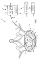
- the system 10 of the present invention includes a combination electrical and chemical stimulation device 12, a stimulation source 14 that communicates with the stimulation device 12 for delivering electrical energy and chemicals to the stimulation device, and an interventional device such as an introducer needle 32 that allows introduction of the stimulation lead.
- the stimulation device 12 is shown as inserted within an intervertebral disc D.
- the combination device 12 more particularly includes a percutaneous electrical and chemical stimulation lead 16 in the form of an elongate tubular member having a desired length and diameter allowing the lead 16 to be placed within the intervertebral disc of the patient to be treated.
- the working distal portion 20 of the stimulation lead 16 provides the desired stimulation through a plurality of electrodes 22 which are selectively positioned on the distal portion 20, along with a plurality of infusion ports 30 which allow delivery of chemicals/nutrients to target tissue.
- the proximal portion of the stimulation device 12 can be referred to as a lead extension 18 that connects to the stimulation source 14.
- the lead extension 18 can be made of the same type and diameter material as the stimulation lead 16, or may be made of a different type of material and diameter.
- a plurality of circumferentially extending electrodes 22 are positioned at the distal portion 20.
- the electrodes 22 are also spaced longitudinally along the distal portion 20.
- the electrodes produce an array of electrical field energy, and the target tissue is immersed in the electrical field.
- One or more electrical conductors 23 extend through the interior of the stimulation lead 16 in order to transmit the electrical impulses to the electrodes 22. It is preferable to utilize a single conductor 23 along the major length of the lead, and then provide branch conductors (not shown) at the distal portion 20 that then extend to contact the various electrodes.
- the branch conductors could be a linearly arranged set of wire extensions extending between each electrode, or any other advantageous combination of wire conductors to interconnect the electrodes. Use of a single conductor is a more robust design as opposed to multiple smaller conductors that are more prone to breakage as a result of the motion cycles of the IVD. It is also contemplated that the electrode could be a single electrode wound in a helical pattern about the distal portion 20. Thus in this helical pattern, only one conductor 23 would be required with no additional branch conductors. In order to generate the desired intensity and size electrical field, the electrodes 22 can be disposed on the distal portion in a pattern or arrangement that best suits the electrical field to be generated.
- the electrode could be wound with a tighter pattern to generate a more intense field, while a looser more spaced pattern would generate a less intense field.
- the particular signal or impulse current provided to the electrodes also determines the intensity of the field generated.
- a central lumen or passageway 24 is formed through the stimulation lead.
- the central lumen 24 may extend completely through the lead thereby forming a distal opening 28 in the stimulation lead and providing one infusion port that is directed distally of the stimulation lead.
- the stimulation lead 16 may be made of a homogeneous material, or may be made of differing materials that cause the stimulation lead to have either a more progressively stiff or more progressively flexible characteristic as the lead extends in the distal direction. Depending upon the manner in which the stimulation lead is to be emplaced, it may be desirable to use either the more progressively stiff or more progressively flexible arrangement.
- a stylet (not shown) is first inserted through the introducer needle 32.
- the introducer needle 32 is emplaced by penetrating the skin and muscle tissue, and ultimately into the disc D.
- the stylet is removed and the stimulation lead 16 is then inserted through the lumen of the introducer needle.
- the stimulation lead 16 is illustrated as being emplaced within the disc D.
- This disc D is shown in cross section along with an adjacent vertebra V.
- the stimulation lead 16 is shown as taking an arcuate or curved path through the disc nucleus N in order to be precisely positioned at the area of the disc to be treated, illustrated as a fissure F which has developed adjacent the spinal fluid sac (not shown).
- the other primary features of the disk D are also illustrated including the annulus fibrosis A and the thin layer L defining the annular nuclear interface/transitional zone.
- the stimulation source 14 is preferably an implantable medical device 34 including both an IPG (implantable pulse generator) 36 and an IDP (implantable drug dispenser) 38.
- the implantable device 34 could be contained within a single structural housing, or two separate housings, one for the IPG 36, and one for the IDP 38.
- the IPG and IDP can both be self-contained devices with internal control for preset delivery of electrical and chemical pulses.
- an external controller 44 could be used to modify the desired treatment protocol by use ofRF transmission wherein an implantable RF receiver 40 is integrated with the IPG 36 and IDP 38.
- the RF receiver 40 could also be housed within the same implantable medical device 34, or could be a separate implanted device.
- An external RF transmitter 42 transmits RF signals to control the delivery of electrical stimulation and chemicals to the stimulation lead 16.
- a controller 44 provides the specific instruction set for transmission by the RF transmitter 42.
- nutrients and medications that can be delivered by the stimulation lead.
- this list includes, but is not limited to, glucose, glucosamine, chondroitin, oxygen and oxygenating agents, anti-oxidants, anti-glycosylating agents, and pH buffers.
- these may include, without limitation, anti-inflammatory agents and growth factors, such as growth and differentiating factor-5 (GDF-5), transforming growth factor-beta (TGF- ⁇ ), insulin-like growth factor-1 (IGF-1), and basic fibroblasts growth factor (bFGF).
- GDF-5 growth and differentiating factor-5
- TGF- ⁇ transforming growth factor-beta
- IGF-1 insulin-like growth factor-1
- bFGF basic fibroblasts growth factor
- these electrical impulses may be continuous or variable over time, and may vary based upon voltage, amperage, and alternate current frequency.
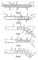
- FIG. 3 a different arrangement is illustrated with respect to the location of the electrodes 22, and the single infusion port at distal opening 28 is supplemented with a plurality of additional infusion ports 30.
- additional infusion ports 30 are provided that are spaced longitudinally along the length of the lead 16 and placed between the electrodes 22.
- Figure 4 shows another embodiment with a different arrangement of electrodes 22 and infusion ports 30 as well as a modification of the stimulation lead shape to include a bent distal tip having a chosen bend angle ⁇ .
- the bend angle ⁇ helps define the path of travel of the lead within the disc nucleus during emplacement.
- imparting a particular bend angle on the distal tip of the stimulation lead causes the stimulation lead to travel in an arcuate path such as shown in Figure 1 .
- Imparting a greater bend angle on the lead results in the stimulation lead traveling in a tighter arcuate path, while imparting a lesser bend angle generally results in the stimulation lead traveling in a broader arc or arcuate path.
- FIG. 5 another embodiment of the stimulation lead is illustrated wherein the lead has a progressively narrowing diameter towards the distal end thereof.
- the electrodes 22 are not formed circumferentially around the distal portion 20, but are formed more linearly along one side of the stimulation lead.
- the infusion ports 30 may have more of an oval shape and be larger in size that facilitates greater volumetric infusion. This embodiment may be preferred when it is desired to more precisely direct the array of electrical energy to the target tissue.
- the electrical energy array that is created by circumferentially arranged electrodes result in transmission patterns having a radial or circular pattern extending away from the stimulation lead.
- a plurality of circumferentially arranged electrodes transmit energy in all directions to tissue that surrounds the stimulation lead.
- Figure 7 illustrates yet another embodiment of the stimulation lead wherein the electrodes 22 are concentrated at a particular location, and the infusion ports 30 are spaced in a pattern extending a greater longitudinal length of the lead.
- a stimulation lead in this particular arrangement may be particularly suitable for repair of a fissure located at a very defined position within the disc, yet if the disc shows great overall degeneration, it is preferable to provide nutrients to a greater length of the annulus whereby the infusion ports 30 can distribute nutrients to a greater length of the annulus.
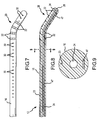
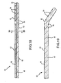
- Figure 8 illustrates yet another preferred embodiment of the present invention wherein a stiffening or strengthening member 47 is incorporated within the structural wall of the stimulation lead to provide increased strength to the lead without enlarging the frontal profile of the lead.
- the stiffening member 47 is an elongate member that extends longitudinally through the wall of the lead and terminates near the distal end thereof.
- the stiffening member is malleable to a degree that allows the lead to maintain some desired flexibility during emplacement, but increases the overall shear and torsional strength of the lead to prevent premature failure after emplacement or during removal.
- the member 47 could be made of a selected metal or thermoplastic , or of various synthetic materials such as Kevlar® and nylon, that are approved for medical use.
- an introducer needle 46 is not placed within the disc nucleus, but rather is placed only into the disc annulus, and then the stimulation lead 16 extends through the disc annulus to the target tissue, also shown as a fissure F.
- the stimulation lead 16 exits the introducer needle through a bent distal portion 48 so that the lead travels in a more parallel fashion within the annulus and along a more linear path to the target tissue.
- a guide wire 26 may be inserted through the lumen 24 of the lead 16, and the distal tip 27 of the guide wire could be placed flush with the distal opening 28 in order to prevent clogging of the distal opening 28, as well as to provide additional rigidity for placement of the stimulation lead 16. If the guide wire 26 is used, then the guide wire 26 is removed prior to connecting the stimulation lead 16 to an IDP and/or IPG. Also, the central lumen may terminate before passing through the distal tip of the lead. Thus, all of the infusion ports 30 would be arranged on the lead to direct chemicals/nutrients in a perpendicular direction away from the axis of the lead.
- Figures 11-13 illustrate yet further embodiments of the present invention wherein the electrodes 22 and infusion ports 30 are dispersed along substantially the entire length of the stimulation lead.
- the disc to be treated has undergone such great degeneration that the entire disc is in need of treatment, as opposed to a more minor degenerative condition such as a single localized fissure. In such cases, it is advantageous to provide both electrical and chemical stimulation to as much of the disc as possible.
- the embodiments at Figures 11-13 show various combinations of the electrodes 22 and ports 30 that provide greater dispersion of the electrical and chemical stimulation. Specifically, the electrodes are larger and are spread out along a greater length of the lead. The infusion ports are also spread out along a greater length of the lead.
- Figure 14 illustrates yet another embodiment of the invention wherein a second lumen 41 is incorporated within the stimulation lead to provide greater infusion selectivity. More specifically, Figure 14 shows that the second lumen 41 terminates at end 39 which is intermediate between the distal tip of the stimulation lead and the proximal end thereof. This lumen 41 communicates with the set of infusion ports 37 which are spaced from the end 39 of the lumen 41 towards the proximal end of the lead. The first or central lumen 24 then communicates with the infusion ports 35 that are located distally of the end 39 of the second lumen 41.
- a physician has the ability to selectively control infusion to two distinct areas within the disc, and can vary the treatment protocol between the two areas of the disc by selecting the particular dosing, frequency, and makeup of the infusion material to the distinct locations within the disc.
- This selective treatment capability may be advantageous where, for example, the distal end of the stimulation lead may be placed near the interface/transitional zone, and the tissue extending there along together with the annulus fibrosis may have particular needs in terms of the required type of nutrients and/or medication, while the tissue within the nucleus may have slightly different needs.
- the embodiment at Figure 14 provides the treating physician with additional options in providing effective treatment.
- the particular sizes of the lumens, as well as the sizes and spacing of the openings 35 and 37 may be configured for optimal delivery of various types of infusion material. For example, assuming that the desired nutrient/medication to be delivered to the distal end of the stimulation lead was fairly viscous, it may be advantageous to provide the lumen 24 with a larger cross-sectional size, as well as to provide the infusion openings 35 of an increased size to accommodate the higher viscosity. As a further example, if the lumen 41 was to deliver a less viscous nutrient/medication, then the lumen 41 would preferably have a smaller cross-sectional area, and the openings 37 would preferably be smaller than the openings 35. Thus, one convenient way in which to control infusion is to advantageously arrange the particular size, number, and spacing of the infusion openings as well as the size of the lumens that deliver the infusion material through the openings.
- the IDP 38 may be programmed for preset delivery of chemical "pulses".
- the IDP 38 is typically programmed to be in an "on” or “off” state to generate delivery of a set amount of fluid over a specific period of time.
- the IDP itself does not have control over the way in which the infusion material is dispersed through the stimulation lead.
- a lumen of a stimulation lead has a uniform diameter with infusion openings also being of a uniform diameter
- the infusion ports located at the more proximal end of the device will most likely deliver a greater amount of material to the disc as opposed to the infusion ports located at the distal end of the device because there will be an inherent loss in the amount of fluid delivered downstream based on frictional losses within the lumen and the upstream openings communicating with the lumen. Therefore, in order to ensure equal distribution of infused material, it may be desirable to provide a lumen having a diameter that progressively enlarges as it extends towards the distal end of the device. Alternatively or in combination with the progressively changing lumen size, it may be desirable to provide infusion ports toward the proximal end of the device that are slightly smaller than the infusion ports located towards the distal end of the device to further help compensate for any frictional line losses.
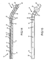
- yet another embodiment of the present invention is provided which further includes an inflatable portion 50 in the form of a bladder or balloon that is selectively inflated or deflated by an inflation line 52 extending conterminously with the central lumen.
- the inflatable portion is mounted to the exterior surface of the stimulation lead, and the inflation line 52 extends through an opening (not shown) in the sidewall of the lead that is covered by the inflatable portion 50.
- the inflation line 52 communicates with a source of compressed fluid (not shown), and the physician may inflate the inflatable portion 50 to a desired size.
- the inflatable portion 50 is preferably placed along a location of the stimulation lead that does not cover or block any infusion ports 30, as well as any electrodes 22.
- the stimulation lead may reside within a patient for an extended period of time. As time passes, the stimulation lead may have a tendency to migrate or drift within the disc. Drifting of the stimulation lead can be problematic for a number of reasons, to include causing damage to the disc by penetration of the distal tip of the stimulation lead completely through the disc, as well as drifting of the stimulation lead so that it is no longer centered around/along the desired area of the disc to be treated.
- the inflatable portion 50 may be inflated to the desired size, thereby serving as an anchor to help prevent driving of the stimulation lead within the disc.
- the inflatable portion 50 may be selectively placed along other areas of the stimulation lead to best serve as an anchor.
- the inflatable portion is located at the proximal end of the stimulation lead.
- Some disc tissue may have a tendency to adhere to a stimulation lead that has been emplaced within the disc for a long period of time, and/or the disc tissue may have a tendency to harden around the emplaced stimulation lead thereby making it more difficult to remove the stimulation lead.
- the inflatable portion 50 could be provided to extend along a much greater distance of the stimulation lead, and the inflatable portion 50 could be inflated to a desired level prior to the stimulation lead being emplaced within a disc. When it is then desired to remove the stimulation lead, the inflatable portion could be deflated which would create a small gap or space between the surrounding disc tissue and the stimulation lead thereby easing removal of the stimulation lead.
- the inflatable portion 50 can be used either as an anchor to maintain positioning of the stimulation lead within the disc, or the inflatable portion 50 can be used in a reverse role by enlarging the overall size of the stimulation lead once emplaced, but then reducing the overall size of the stimulation lead by deflating the inflatable portion when it is desired to remove the stimulation lead.
- a stimulation lead is shown emplaced within a disc D, the stimulation lead generally corresponding to the embodiment shown in Figure 14 .
- Two oval shaped areas 40 and 42 are shown surrounding the distal and proximal sections of the stimulation lead, respectively. These areas 40 and 42 may generally represent targeted treatment areas within the disc.
- the physician has the option of applying different infusion materials through the separate sets of infusion ports 35 and 37 to specifically target the tissue located within the areas 40 and 42. Such treatment could be simultaneous, sequential, or any combination thereof.
- selected sets of electrodes could be energized to provide treatment.
- the electrodes may be wired so that the physician has the ability to energize two primary sets of electrodes, one set providing an electromagnetic field generated to cover area 40, and the other set providing an electromagnetic field to cover area 42.
- the electrodes may be wired and configured to provide generation of electromagnetic fields in any desired pattern along the length of the lead.
- FIG. 18-20 yet another embodiment of the present invention is illustrated in the form of stimulation lead 60.
- the embodiment of Figure 18 contemplates the use of various chemical agents/medications and nutrients incorporated within a dissolvable matrix that forms the body 62 of the stimulation lead 60.
- the electrodes 64 as well as the conductor(s) 66 could be formed with the dissolvable matrix in a molding process whereby a particular shape and size stimulation lead could be produced.
- the electrodes 64 could function the same as the electrodes 22 discussed above and could be produced in any desired pattern and wiring arrangement.
- the dissolvable matrix can be made of a material that is biomedically acceptable for enabling a time release of the chemical agents/medications and nutrients mixed within the matrix.
- the matrix is preferably a solid yet flexible material, allowing the stimulation lead to be steered with the use of an insertable stylet 56 which could be provided through the central lumen 68.
- this central lumen 68 is optional, and the matrix may be manufactured of a material which is durable yet flexible enough allowing the practitioner to steer the stimulation lead without the use of a stylet.
- Figure 19 illustrates another embodiment wherein there is no lumen present, and a predetermined bend angle is formed in the stimulation lead enabling the lead to take the desired path through the disc when emplaced.
- the matrix Once inserted into the disc, the matrix would dissolve and the regenerating chemicals/medications and nutrients would slowly diffuse into the surrounding disc tissue leaving only the electrodes 64 and conducting wire(s) 66 to be removed at some later time.
- an infusion pump would not be required, and would thereby also allow for the subcutaneously placed pulse generator (IPG) to be significantly smaller. Similar to the combined pump/pulse generator device described above, this much smaller pulse generator could be rechargeable, or be powered by a battery source as desired.
- IPG subcutaneously placed pulse generator
- a stimulation lead can simply comprise a dissolvable matrix having a desired combination of chemical agents/medications and nutrients, and no electrodes incorporated within the lead.
- stimulation by an electromagnetic field may be unnecessary to achieve the desired regenerative and/or pain relieving disc response.
- Figure 20 illustrates the designated cross-section of the device in Figure 18 . Additionally, Figure 20 illustrates the use of an optional outer membrane 72 which could serve multiple purposes. One purpose for the membrane 72 would be to support the structural integrity of the matrix material of the body 62, thereby providing additional support for when the stimulation lead was emplaced. Additionally, this membrane 72 could serve as an osmotic membrane to help meter the rate at which the chemical agents/medications and nutrients were allowed to diffuse into the surrounding tissue. Thus, in addition to the matrix having a predetermined rate of diffusion, the membrane 72 could be used as an additional means to control the rate at which the chemical agents/medications and nutrients were delivered to the surrounding tissue.
- the membrane 72 is provided only for structural support to the lead when emplaced, the membrane could be made of a material that quickly dissolves after being emplaced within the disc and the diffusion rate would be entirely controlled by the particular diffusion characteristics of the matrix.
- a stimulation device may be used to treat SI joint ailments.
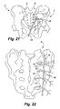
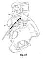
- Figure 21 specifically illustrates a posterior view of the sacroiliac region with an introducer needle positioned for insertion along the sacroiliac region to a targeted area adjacent the SI joint J.
- Figure 22 an enlarged posterior view of the sacrum bone B is shown wherein the introducer needle 46 has been fully inserted.
- the introducer needle 46 is first inserted through the skin below and slightly medial to the inferior aspect to the SI joint and directed towards the inferior lateral edge of the sacrum.
- the introducer needle 46 is advanced to contact the dorsal aspect of the sacrum at the posterolateral edge.
- the needle 46 may have a slight curvature near the distal end thereof, shown as curve or bend 48, and the curvature of the bend 48 is then utilized to advance the needle lateral to the sacral foramen and medial to the dorsal aspect of the SI joint.
- the distal tip can have a shaper bend and the needle have a continuous curve along all or part of its length to further facilitate positioning along , and parallel to the sacral curvature.
- the needle 46 remains in contact with the periosteum along the entire curvature of the sacrum.
- the needle tip ultimately advances to the superior edge of the sacrum lateral to the sacral foramen and medial to the SI joint. Appropriate positioning of the introducing needle is confirmed preferably both on Antero-posterior (AP) as well as lateral views.
- the stimulation lead 16 is then inserted through the introducer needle 46 until reaching the distal tip 48 of the introducer needle. The stimulation lead 16 is held in place by maintaining pressure on the lead.
- the introducer needle 16 is withdrawn along a selected length of the stimulation lead 46 to expose the active number of electrodes 22 necessary to denervate the sacral nerve innervation to the SI joint.
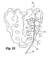
- the dotted lines shown in Figure 23 for lead 16 represent the initial position of the lead after the needle 46 is withdrawn.
- local anesthetic and/or neurolytic agents and/or proliferant agents such as, but not limited to, phenol or alcohol, or Dextrose respectively could be injected through one or more of the infusion ports.
- the electrodes 22 may then be activated to ablate the surrounding neural tissue.
- the dotted lines for needle 46 in Figure 23 represent the position of the needle after it has been withdrawn and the lead is ready for activation.
- the solid lines in Figure 23 represent the next position of the lead 16 and needle 46 wherein both have been further withdrawn for purposes of conducting another activation to further denervate tissue, such as a circumstance when the initial ablation did not effectively cover the desired area of tissue.
- the stimulation lead for use in a method of treating the SI joint, it may be constructed in the same manner as disclosed with respect to the prior description for treatment of a disc. More specifically, a stimulation lead may be selected having the most desirable arrangement of electrodes for the most optimal denervation of the targeted neural tissues.
- the sacral nerves illustrated in Figure 23 include the lateral branches S1, S2, S3 and S4.
- each of the lateral branches it may be required to sequentially apply energy to the stimulation lead as the introducer needle is repeatedly withdrawn along the path of insertion.
- successful denervation may require two or more separate needle insertion angles in order to denervate the S1-S4 lateral branches.
- the figures show treatment along one side of the sacrum, it shall be understood that the same procedure may be repeated for treatment of the other side of the sacrum, by placement of the introducer needle in a symmetrical fashion on the corresponding opposite or contralateral side of the sacrum.
- electrical stimulation it is also contemplated with respect to the method of treatment of the SI joint to also provide infusion in a combined electrical stimulation and chemical/drug infusion device.
- infusion of collagen proliferants could be included in the method of treatment by use of a selected device including any one of the above-disclosed embodiments. Infusion of collagen proliferants such as dextrose, growth factors, and other nutrients may accelerate the healing process for some SI joint ailments.
- infusion alone may be appropriate for the treatment, or in combination with some neural tissue ablation or stimulation. It is also contemplated in the method of the present invention to enhance neurolytic lesion size by infusion of substances such as Phenol, alcohol, and glycerin.
- Figure 24 illustrates yet another preferred embodiment of the present invention.
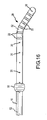
- the stimulation lead has a substantially uniform curvature over a selected length of the stimulation lead. The amount of curvature provides a desired angle for extending the stimulation lead within the targeted area of the body.
- the distal end 20 of the stimulation lead is similar to what is shown in Figures 4 and 6 , and therefore may have an additional bend that assists the medical practitioner in steering the stimulation lead once it has exited the distal end of the introducer needle 32.
- This particular shaped stimulation lead may also be advantageous in conducting treatment of the SI joint as discussed above with respect to Figures 21-23 .
- Figure 25 illustrates the stimulation device of Figure 24 for purposes of treatment of vertebral structures other than a disc, such as ventral vertebral structures that are to be ablated.
- Figure 26 illustrates yet another preferred embodiment of the present invention wherein the stimulation lead is substantially liner or straight, and a stylet 76 is placed through a central lumen of the stimulation lead.
- the stylet 76 may be used to steer the stimulation lead, and to provide the necessary stiffness to the stimulation lead during emplacement. Once the stimulation lead has been manipulated to the desired position, the stylet 76 can be removed while keeping the stimulation lead stationary. Then, the desired electrical stimulation procedure can be conducted along with any desired infusion.
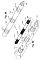
- a stimulation lead 250 is illustrated that can either be used as a reusable stimulation lead placed within an outer sheath (see e.g., Figure 32 ), or the stimulation lead 250 may be used by itself as a disposable stimulation lead.
- the stimulation lead 250 includes a stimulation body 252, and a plurality of electrodes 254 that are located at the distal end of the body 252.
- the tip 255 may be blunt, or may include a trocar, Quincke, Touhy, or other penetrating/cutting type tip if the stimulation lead is to be forced through fairly dense tissue.
- a handle 256 is provided wherein the handle includes a central web 258, and a pair of transverse flanges 260 that extend substantially perpendicular to the central web 258. With the handle 256, the combination of the transverse flanges 260 and the web 258 allow the handle to be manipulated to rotate, twist, push, or pull the body 252 to precisely locate the stimulation lead. If it is desired for the device to be able to provide infusion, a fluid line 262 can be provided that communicates with a central lumen 259 of the stimulation lead such that infusion may take place through selectively located infusion ports 261. A cable 264 and multi-pin connector 266 are provided to power the electrodes 254.
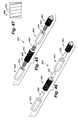
- FIG. 28 an enlarged fragmentary perspective view is provided illustrating how the electrodes 254 may be secured to a non-conductive sheath 253.
- the non-conductive sheath and electrodes collectively make up the body.
- the non-conductive sheath 253 may be made of material such as plastic.
- An opening 255 may be made in the sheath to receive wires 278 which in turn are connected to conductors 272 and 274 forming a thermocouple. Junction 276 terminates the opposite ends of the pair of wires 278.
- the electrode 254 is in the form of a tubular member that fits over the sheath 253 and is secured to the sheath 253 by an appropriate adhesive, crimping, or other techniques.
- the wires 278 and thermocouple contact the electrode 254.
- connection of the electrodes 254 over the sheath 253 is preferably watertight such that the central lumen 259 is shielded from the external environment.
- Wires 278 conduct power to the electrodes to include RF signals, as well as serving as conductors for measurement of electrical potential between the thermocouple elements 272 and 274.
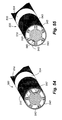
- FIGS 29 and 30 illustrate a disposable sheath 290 that can be used in conjunction with a reusable stimulation lead 250 of Figure 27 .
- the disposable sheath 290 may include a plurality of conductive sections 292 which act as electrodes when placed in electrical contact with the electrodes of the reusable stimulation lead. Insulated non-conductive connectors 294 interconnect each of the electrodes 292.
- One simple method of connection is to provide smaller diameter flanges for the conductive sections, shown as flanges 296 and 298, and then press fit the sections together.
- a spring finger conductor 300 Within each conductive section 292 is a spring finger conductor 300. The conductors are placed within each of the conductive sections 292 such that the traversing pattern of fingers 302 presses against the interior surface of the conductive sections 292.
- a desired shaped tip 304 may be provided for the sheath, shown in Figure 29 as a trocar type tip having a tapered sharpened end 304, and a base 306 that is received in the most distal end of the conductive section 292.
- the reusable stimulation lead 250 shown there is the same as stimulation lead 250 shown in Figure 8 , except that the infusion line 262 has been eliminated.
- the body 252 of the stimulation lead 250 is inserted within the disposable sheath 290 so that the electrodes 254 of the stimulation lead align with the conductive sections 292, while the non-conductive sections 257 of the stimulation lead 250 align with the non-conductive sections 294 of the sheath.
- the fingers 302 make frictional contact with the electrodes 254; the fingers 302 also being in contact with the conductive sections 292 creates an electrical pathway such that energizing selected one or all of the electrodes 254 results in energizing the corresponding conductive sections 292.
- temperature-sensing elements such as a thermocouple may be incorporated in the stimulation lead 250 as disclosed above in Figure 28 .
- the temperature of the conductive sections 292 may be measured since by conduction, thermal contact is maintained between the active areas of the stimulation lead and the conductive areas on the external sheath.
- One clear advantage of providing a disposable sheath 290 is that the sheath may be sized, shaped and otherwise designed for conducting a desired procedure. Use of a reusable stimulation lead lowers the cost of the procedure since the entire assembly does not have to be replaced in the next procedure; only the disposable sheath.
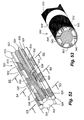
- FIG 33 an alternate type of reusable stimulation lead 340 is illustrated.
- Figure 33 only illustrates the body 342 of the stimulation lead, it being understood that this embodiment may also include a handle, cable, an electrical connector, the same as shown in Figure 31 .
- a plurality of flexible electrical conductive pods 348 may be disposed at selected locations on the body 342.
- Each pair of wires may include a thermocouple 344 that is placed in the electrical contact with conductive pods 348.
- wire pairs 346 may be used to provide RF signals, as well as conductors for measuring differences of electrical potential at the thermocouples 344.
- the stimulation lead 340 may then be inserted within a disposable sheath, such as the one discussed above with respect to Figures 29 and 30 , or with an alternate sheath assembly discussed below with respect to Figures 34-36 .
- this alternative sheath embodiment 310 is characterized by a very flexible body 312 having a plurality of slots or openings 314 formed therein.
- a distal end of the body 312 includes a tip 316.
- the tip can be blunt or sharp, depending upon the intended use.
- electrodes 318 are cylindrical shaped sections that are slipped over the body 312, in the same manner as disclosed with respect to Figure 28 .
- a bracket 320 is used to interconnect the electrodes from the reusable stimulation lead with the electrodes 318 formed on the sheath.
- the bracket 320 may include a pair of traverse flanges 322, sidewalls 326, and base 328.
- a channel 324 is formed between the sidewalls and base.
- the bracket 320 is placed in a corresponding slot 314 such that the flanges 322 rest on the outer surface of the body 312.
- the electrode 318 is aligned such that it covers the bracket 320.
- the electrode 318 is secured to the body 312 as by crimping, or by spot welding. Adhesive may also be used to ensure there is a liquid tight seal. In Figure 36 , the thickness of the electrode 318 has been accentuated to enable understanding of how the electrode 318 is secured.
- the body 312 and electrodes 318 it is preferable to provide a substantially smooth and continuous outer surface for the body 312 and electrodes 318, or at least a minimal protrusion of the electrode 318 above the outer surface of the body 312.
- One technique to ensure a smooth outer surface would be to form a channel in the body 312 to accept the electrode 318.
- the electrodes of the reusable stimulation lead make contact with the respective bases 328 of the brackets 320, thereby also energizing the respective electrodes 318.
- the three linearly aligned electrical conductive pods 348 make contact with the three linearly aligned brackets 320.
- an opturator 360 may be used when first emplacing the disposable sheath in a position where treatment is to be applied. Because of the very thin body 312, interior support of the opturator is necessary prior to insertion of the reusable stimulation lead.
- the opturator may have a standard end connection or flange 362 enabling it to be controlled in placing the disposable sheath 310.
- FIG 37 illustrates another configuration of the embodiment of Figures 34-36 wherein an alternate shaped bracket 350 is provided.
- This bracket 350 includes a curved base 352, and a pair of opposing end flanges 354 that make contact with the outer surface of the body 312.
- the electrode 318 is slipped over the body 314, and the electrode 318 covers the bracket.
- the conductive pod 348 makes contact with the curved base when the stimulation lead 340 is placed within the sheath. Because of the curved shape of the bracket 350, some resiliency is present when the pod 348 makes contact thereby ensuring a good electrical connection.
- Figures 38 and 39 illustrate yet another preferred embodiment of the present invention in the form of a disposable sheath and reusable inner stimulation lead or probe.
- a reusable probe 400 is shown having a plurality of spaced active areas or electrodes 402, a distal end 406, and insulated, non-conductive sections 404 located between the electrodes 402.
- the disposable sheath 410 of the present invention is shown fully manufactured in Figure 39.
- Figure 38 illustrates the disposable sheath during manufacturing wherein a plurality of electrode assemblies 412 are selectively spaced from one another along an inner mandrel 418.
- a sharp metallic or plastic tip, such as a trocar 420, is secured to a distal end of the mandrel 418.
- Each of the electrode assemblies 412 include a plurality of electrode elements 414 that extend longitudinally along a length of the corresponding electrode assembly, and the elements 414 are spaced from one another circumferentially around the electrode assembly.
- An electrode sleeve 416 serves as a base to secure the electrode elements 414.
- the electrode assemblies to include the electrode elements and sleeves are made of a desired conductive material.
- the electrode elements 414 are shaped such that they extend radially away from the longitudinal axis of the mandrel in an arc shape. Therefore, the electrode elements 414 extend a radial height above the outer surface of the respective electrode sleeves 416.
- a non-conductive thermoplastic material is then applied over the mandrel 418, such as by molding or by spray deposition wherein a sheath body 422 is formed.
- the electrode sleeves 416 and some parts of the electrode elements 414 are embedded within the applied sheath material. Accordingly, the electrode members have at least an outer most radial surface that remains exposed.
- the particular sheath body material may be selected to provide the desired flexibility or stiffness for the disposable sheath. Additionally, the sheath material can be applied at a desired thickness to account for the amount of the electrode elements 414 to be exposed.
- the mandrel 418 is then removed from within the now formed disposable sheath wherein the cylindrical inner surfaces of the electrode sleeves 416 are exposed within the interior of the sheath.
- the electrodes 402 align with the respective electrode sleeves 416, thereby achieving electrical contact between each of the electrode assemblies 412 and respective electrodes 402.
- the device then may be used to conduct a desired procedure wherein the exposed portions of the electrode elements 414 are used to deliver energy to the patient.
- the sheath body material may extend over a base or proximal portion of the trocar tip 420 such that a good seal is achieved and thereby completely isolating the stimulation lead within the disposable sheath.
- FIG. 40 illustrates a stimulation lead, such as stimulation lead 400, that is placed within a disposable perforated sheath 430.
- the perforated sheath 430 includes a plurality of perforated sections 432, each section having a plurality of openings that therefore expose the respective electrodes of the stimulation lead. More specifically, with the stimulation lead 400 of Figure 40 , three electrodes are illustrated, namely a most distal electrode 450, and two spaced proximal electrodes 446 and 448.
- the electrodes 446, 448, and 450 align with respective perforated sections 432 of the sheath.
- the sheath 430 is made of a non-conductive material, but the thickness of the material is very thin such that when the stimulation lead is placed within a patient, tissue of the patient is allowed to penetrate the perforations 432 and
- the sheath provides protection to the stimulation lead, thereby increasing its life.
- the stimulation lead must be resterilized after use, but the disposable sheath provides a protective jacket without substantially inhibiting the ability of the electrodes to deliver energy to targeted tissue.
- FIG 41 illustrates yet another disposable sheath 440 of the present invention.
- the disposable sheath 440 includes a plurality of insulated or non-conductive sections 442, and at least one conductive area or section 444.
- the conductive section 444 also includes a plurality of openings formed therein, therefore making the conductive section 444 appearing as if it is perforated.
- One specific use for the disposable sheath 440 shown in Figure 41 is to alter the electrode pattern of the inner stimulation lead 400.
- the longitudinal length of the conductive area 444 causes it to bridge between the underlying electrodes 446, 448, and 450 thereby creating one continuous and larger sized electrode that will result in creation of a different ablative pattern once the stimulation lead is energized.
- the disposable sheath 440 may have a desired configuration of insulated areas and conductive areas that alter the basic electrode pattern of the underlying stimulation lead.
- the benefits of this embodiment also include some protection for the inner stimulation lead.
- Figures 42-44 illustrate yet further embodiments of the present invention, showing in more particular detail various construction techniques for forming stimulation leads that have a selected pattern of electrodes and non-conductive sections.
- the stimulation lead 460 is shown in the form of a segmented probe having a plurality of electrode sections 462 spaced between respective non-conductive sections 464. Electrical continuity can be achieved between the various electrode sections 462 by the use of conductive extensions 466 that are inserted within the openings formed through the adjacent non-conductive sections 464.
- the stimulation lead 460 in Figure 42 has a distal stimulation lead 462 incorporating a trocar tip 474.
- each section 464 can incorporate various constructions to include conductive wires wound in a pattern, solid electrical members, and others.
- the proximal ends 469 of each conductive extension 466 are inserted into distal ends of the adjacent non-conductive sections 464.
- the distal ends 468 of the electrode extensions 460 are inserted in the opposite, proximal ends of the adjacent non-conductive sections 464.
- the abutting ends 468 and 469 within each non-conductive sections make contact with one another, thereby providing electrical continuity between the electrodes.
- the diameter of the conductive extensions 466 may be such that a friction fit is achieved between the conductive and non-conductive sections.
- An approved epoxy may also be used to ensure that the sections do not separate from one another.
- the conductive extensions 466 may include a plurality of conductive pins (not shown) that selectively mate with corresponding pins (not shown) of other conductive extensions, thereby providing the capability to alter or change the electrical connections between the respective electrodes.
- an RF generator driving the stimulation lead can have settings that cause leads to be activated only in the mono-polar configuration, whereby the electrical pins between the conductive sections conduct RF power signals and a grounding pad is used.
- the electrical pins would conduct RF power signals in a different manner between the electrodes as controlled by the RF generator.
- Figure 43 illustrates a stimulation lead similar to the one described above with respect to Figure 42 , except that the stimulation lead in Figure 43 includes a plurality of splines 476 that are used to ensure a tight connection between the conductive and non-conductive sections.
- the splines 476 are secured to the conductive extensions 466 and have free ends that extend at a radial angle away from the longitudinal axis of the stimulation lead.
- the free ends of the splines 476 may be sharpened or pointed.
- the free ends of the splines make contact with the interior wall of the non-conductive section, thereby providing frictional resistance against pullout.
- Figure 44 illustrates yet another modification to the stimulation lead illustrated in Figure 42 .
- the conductive and non-conductive sections may be secured to one another by incorporation of a key/keyway arrangement. More specifically, the conductive extensions 466 each have a key 470 that protrudes radially, and is received in keyways 472 which are formed at the ends of the adjacent non-conductive sections 464. The shape of each keyway 472 may be such that each key 470 is prevented from removal from within the corresponding keyway.
- the keyways 472 are L-shaped allowing the keys 470 to lock in the keyways 472 by rotating the keys to reside in the transverse slots of the keyways.
- Figures 45 and 46 illustrate yet additional construction details for the manufacture of a stimulation lead in accordance with another modification to the present invention.
- the conductive extensions are threaded extensions 480 that are received in internally threaded openings 478 of the non-conductive sections.
- the abutting distal and proximal ends of the conductive extensions 480 within each non-conductive section make contact with one another to thereby achieve electrical continuity between the electrodes in the same manner as described above in Figure 42 .
- yet another construction option includes the use of interconnecting pegs 482 that interconnect the respective conductive and non-conductive sections.
- the abutting distal and proximal ends of the pegs 482 within each non-conductive section make contact with one another to thereby achieve electrical continuity between the electrodes also in the same manner as described above in Figure 42 with respect to the conductive extensions.
- the construction details for the stimulation lead shown in Figures 42-46 allows for creation of a stimulation lead having conductive and non-conductive sections that are mechanically locked to one another and also provides a designer with many options in terms of selecting the length and size of the conductive and non-conductive sections to be used.
- Figure 47 is an enlarged view of one particular construction for an electrode 490.
- the electrode is simply a conductor such as a wire 492 that forms a helical pattern on the stimulation lead.
- the electrical characteristics of the electrode may be easily altered and therefore, making possible the use of the stimulation lead with very different types of electro-surgical procedures.
- a disposal sheath 500 is illustrated.
- the disposal sheath 500 is shown in a first manufacturing step wherein a tubular piece of material or blank is provided having a molded interior defined by a central lumen or opening 501 extending therethrough.
- a plurality of circumferentially spaced gaps 508 extend radially away from the central or longitudinal axis defined by the lumen 501.
- the tubular piece of material is milled or cut to form the configuration shown wherein selected portions of the outer surface 503 of the material are removed thereby forming a plurality of legs 506 that are spaced from one another by the gaps 508. Selected portions of the outer surface 503 are not removed and remain thus forming insulating spacers 504 that serve as non-conductive sections of the disposable sheath.
- conductive material is applied over the milled or cut sections 502 thus forming respective electrodes 510.
- Each of the electrodes 510 includes an outer peripheral conductive portion 512 as well as a plurality of radial conductors 514 which fill the gaps 508.
- the radial conductors 514 terminate at interior edges 515, and which complete a substantially circular lumen 501.
- Examples of conductive material that may be used to form the electrodes include conductive resins that are molded to form the electrodes in the shape as shown in Figures 50 and 51 .
- Another material in which to form the electrodes 510 includes metallic cylindrical bands with integral radial conductors that are sized and shaped to fit the particular milled or cut pattern of legs 506 and gaps 508.
- a stimulation lead such as the stimulation lead 400, may be placed through the lumen 501 where the electrodes on the stimulation lead align with the radial conductors 514 exposed within the lumen.
- the distal end of the sheath may be sealed thereby allowing the reusable inner stimulation lead to be reused without the need for re-sterilization, and may also include a sharpened distal tip, such as a trocar point, milled from the blank.
- the sheath 500 may be formed in a desired curved shape and may be made relatively stiff or have some flexibility, depending upon the types of material used for the blank and the electrodes. Since each of the conductive areas/electrodes on the sheath are isolated from one another electrically, the same activation functionality provided for the stimulation lead can be maintained with use of the sheath.
- Figure 52 illustrates a reusable-keyed probe or stimulation lead 520 that is used with the outer sheath 500 illustrated in Figures 53-55 .
- the reusable-keyed probe 520 is characterized by a central portion 522 having a substantially cylindrical shape.
- a plurality of circumferentially spaced keys 524 extend radially away from the central portion 522.
- a plurality of conductive rings and conductive extensions are incorporated on the probe. More specifically, a most distal conductive ring or strip 526 extends continually over the keys and central portion.
- a conductive extension 527 is electrically connected to the conductive ring 526 and extends along a channel between respective adjacent pairs of keys 524.
- Another conductive ring or strip 528 is spaced proximally from conductive ring 526.
- Conductive ring/strip 528 has its own corresponding conductive extension 529, which extends proximally within another channel between a corresponding pair of keys 524. Yet another conductive ring or strip 532 is spaced proximally from the ring/strip 528 and the conductive ring/strip 532 has its own proximally extending conductive extension (not shown) which extends along another channel located between a corresponding pair of keys 524. Referring to the conductive extension 527, it is seen that this conductive extension does not make electrical contact with any of the other conductive rings or conductive extensions.
- the conductive ring/section 528 terminates at ends 530 and 531 such that there is no electrical contact between conductive ring 528 and conductive extension 527.
- the conductive extension 527 extends further proximally along the keyed probe, it is shown that the conductive ring/strip 532 has respective ends 533 and 534 that do not allow the conductive ring/strip 532 to contact the conductive extension 527. It is also noted in Figure 52 that the conductive extension 529 is not contacted by any other conductive ring/strip or conductive extension, noting that one end 534 of the conductive ring/strip 532 terminates at a spaced distance from the conductive extension 529.
- a plurality of longitudinally spaced yet electrically isolated conductive rings may be provided along the length of the keyed probe.
- the keyed probe 520 is illustrated with respect to a disposable sheath 500.
- the sheath 500 shown in Figures 53-55 is the same as shown in Figures 48-51 , with the exception that the radial conductors 514 are replaced with radial conductors 543 that extend into the respective gaps 508, but do not completely fill the gaps and therefore create a channel to receive the corresponding keys 524.
- the radial conductors 543 preferably extend along only a portion of the length of the corresponding gap, with the exception of conductive portions which are used to make contact with corresponding conductive extensions of the key probe, as discussed further below. The radial conductors 543 therefore only cover an outer radial portion of the keys 524.
- the arrangement of the most distal conductive section 510 is such that an inner peripheral conductive portion 545 of this conductive section 510 makes intimate contact with the conductive extension 527, thereby allowing energy to be delivered to the patient along the circumferentially extending conductive section 510, and wherein the energy delivered to the conductive section 510 is electrically isolated from the other electrodes/conductive sections 510 and thus may be independently controlled.
- this cross-section taken along line 54-54 Figure 52 shows that the conductive ring/strip 528 makes contact with the intermediate or middle conductive section 510 and further wherein conductive portion 547 aligns with conductive extension 529 such that energy may be conducted from conductive extension 529 throughout this conductive section 510. Since the intermediate conductive section 510 and conductive strip 528 are also electrically isolated from the other conductors and conductive sections, this electrode 510 may be independently controlled.
- this cross-section is taken along line 55-55 of Figure 52 showing that conductive ring/strip 532 makes electrical contact with the proximal conductive section 510. Conductive portion 549 makes intimate contact with the corresponding conductive extension (not shown) of ring/strip 532 such that this proximal conductive section 510 can also be independently controlled.
- both the keyed probe 520 and sheath 500 may be considered disposable wherein the probe 520 during manufacturing is secured within the sheath.
- sheath/probe combination may be emplaced with or without the need for an introducer needle.
- conductive paths are provided to the electrodes on the sheath, wherein the conductive paths are electrically isolated from one another and therefore, both mono-polar and bipolar ablative lesions can be obtained at various locations and combinations along the length of the probe.
- the central lumen 501 and the gaps 508 have been illustrated as extending parallel with the longitudinal axis of the sheath 500, it should also be understood that the gaps 508 may extend in a helical configuration and therefore, the keyed probe 520 may also be provided in a helical configuration to match the orientation of the helical gaps 508. This spiraled or rifling configuration may further help to prevent shifting of the keyed probe with respect to the external sheath.
- a disposable stimulation lead 600 is illustrated in accordance with yet another preferred embodiment of the present invention.
- a handle 602 has a pair of crescent shaped notches or indents 604 that facilitate grasping by the user.
- a proximal end 608 of the handle 602 incorporates an integral electrical receptacle 618, as shown in Figure 57 .
- An electrical plug 610 is mateable with the receptacle 618, and as shown in Figure 57 , a desired electrical pin arrangement 616 is adapted for connection to the receptacle 618.
- a stimulation lead 624 extends from the distal end 606 of the handle 600.
- the stimulation lead 624 includes a desired arrangement of active areas/electrodes 630 separated by corresponding insulated or non-conductive areas 632.
- the electrodes 630 are powered by the RF generator 614.
- Electrical conductors (not shown) extend through the interior of the handle 602 and electrically interconnect the electrodes to the receptacle 618.
- infusion ports 633 may be selectively spaced along the stimulation lead and a central lumen may be used to convey infusion material to the ports.
- the shape of the stimulation lead 624 resembles the shape of the stimulation lead illustrated in Figure 24 wherein a slight curvature is incorporated substantially along the length of the stimulation lead.
- the distal tip or portion of the lead may have a bend that does not follow the curvature of the rest of the stimulation lead, however this bend is co-planar with the rest of the stimulation lead. This bend can be slight or more pronounced depending upon how the practitioner wishes to emplace the lead in its path to the targeted area.
- thermocouples such as thermocouples, RTDs, or other temperature sensing elements
- the embodiment of Figure 56 may incorporate temperature-sensing elements
- Figure 28 provides one example by which a thermocouple may be incorporated in the embodiment of Figure 56 .
- the stimulation lead 600 of Figure 56 can also be used with respect to the method of treating the SI joint as illustrated in Figure 58 .
- the location of the stimulation lead is shifted as compared to the location of the probe shown in Figure 21 .
- the position of the probe in this method creates a lesion of the lateral branches of the nerves as the lateral branches converge as a mesh adjacent the dorsal joint, within the enclosed spaced defined between the iliac crest/ilium above, the SI joint laterally, and the sacrum below.
- the stimulation lead 624 is inserted through the skin at the same inferio-medial position to the targeted SI joint, however the stimulation lead is not placed just lateral to the foramen but is placed more laterally to lie captured under the iliac crest/ilium and in contact with the sacrum, on or directly medial to the dorsal SI joint. Accordingly, the lateral branches at their origin as they extend from the foramen are not lesioned, but rather, the lateral branches are lesioned in the defined enclosed space.
- One advantage to the placement of the stimulation lead in this method is that the stimulation lead denervates a mesh of nerves that are well confined in a relatively tight space and therefore, a more predictable location is selected for treatment of the SI joint.
- additional nerve branches can be denervated, such as the nerve branches extending from the lumbar segments.
- Another advantage in this method is that since the lesion is confined within the defined enclosed space, it is possible to generate a large cylindrical lesion that would entirely fill the space, thereby ensuring adequate lesioning of all of the nerve tissue within the enclosed space. Further, because the lesion is guarded by the sacrum, injury to the skin, even in a small patient, is very unlikely. Additionally, the tissues in this confined location are most exclusively ligamentous, and thus a much more consistent lesion can be made since the resistive characteristics of the tissue are constant throughout the area contacted.
- the stimulation lead 624 in Figure 58 is placed more laterally to lie captured under the iliac crest, in contact with the sacrum, and either on or immediately medial to the dorsal SI joint.
- this figure also shows placement of the stimulation lead 624 where it lies captured under the iliac crest 700, in contact with the sacrum 702 and on or immediately medial to the SI joint 704.
- Figure 59 is only a two-dimensional representation of placement of the stimulation lead with respect to the sacroiliac region, those skilled in the art can understand how from the foregoing description along with the figures that the stimulation lead is placed within the defined confined space to achieve creation of an ablative area which can effectively render the surrounding nerve tissue non-functional
- a cylindrically shaped lesion can be effectively created by selecting a particular sequence and mode of lesioning through activation of selected electrodes on the stimulation lead.
- FIG 60 it is shown that there are three active areas or electrodes 630 on the stimulation lead. Mono-polar activation of the respective electrodes results in generally circular or curved shaped lesions created, shown as lesions L 1 , L 2 , and L 3 .
- the lesions L 1 , L 2 , and L 3 are generally formed in a spherical shape where there may be definable gaps or spaces between the lesions, annotated as spaces S 1 and S 2 . If the electrodes 630 are positioned closer to one another, then it may be possible to reduce the gaps or spaces between the individual lesions; however, because of power constraints with RF medical devices, it is difficult to generate a lesion large enough to treat the entire targeted SI joint without having to conduct a series of activations and by then moving the stimulation lead to a next location and then energizing the electrodes again. Therefore, at least with respect to treatment of the SI joint, it is not feasible to simply provide one long electrode that can generate enough energy to ablate the surrounding tissue.
- the mode of operation of the stimulation lead is changed such that the spaces S 1 and S 2 can be filled in by lesions L 4 and L 5 .
- Lesion L 4 may be created by a bipolar activation of the most distal electrode and the middle electrode.
- Creation of lesion L 5 may be created by a bipolar activation of the middle and proximal electrodes.
- the sequence of activation would be mono-polar activation of the electrodes to create lesions L 1 , L 2 , and L 3 , followed by bipolar activation of the distal and middle electrodes, and bipolar activation of the middle and proximal electrodes to form lesions L 4 and L 5 .
- a sequence of software commands could allow the user to manipulate not only the length of time and power applied to the electrodes, but also the specific sequence to include the bifurcated mono-polar and bipolar activations.
- Figures 60 and 61 also illustrate radio opaque markers 640 that can be used to better visualize the exact location of the electrodes 630 during a procedure.
- Electrodes may be typically made from stainless steel. Electrodes made of stainless steel are very difficult to see, for example, when using fluoroscopy during the procedure being conducted. Thus, it is difficult for the practitioner to know the exact location of the electrodes, which therefore negatively affects the ability to precisely locate the ablative pattern to be created.
- the radio opaque markers 640 may be small bands made of radio opaque materials, such as platinum or iridium.
- These bands as shown can be located at the proximal and distal ends of the electrodes such that when a practitioner visualizes the placement of the device during a procedure, the markers 640 clearly delineate the locations of the electrodes and therefore allowing precise placement of the device to create the desire ablative pattern.
- the most distal electrode could also have a distal marker however it would be understood that the proximal marker for the most distal electrode would suffice for locating that electrode in an image being viewed.
- Treatment of the SI joint may be achieved by a single element wherein the probe does not require the use of an introducer needle, stylet, or any other guidance device.
- complete denervation may be achieved by a single placement of the stimulation lead at the location shown in Figure 58 and 59 .
- an adequately sized lesion is generated to treat the SI joint and the stimulation lead does not have to be repeatedly repositioned or reinserted into the patient for further lesioning.
- the unique handle design maximizes push and twist maneuverability for the user such that the stimulation leads may be placed in the desired area within the sacral region.
- Another example medical procedure that may be conducted with one or more of the stimulation leads of the present invention includes treatment of the superior hypogastric plexis.
- the patient will be placed in a prone position.
- the vertebral body end plates of L5 and S 1 would be brought into alignment with a fluoroscopy beam.
- An introducer needle is inserted lateral to the superior articulur process of S 1 and infero-medial to the L5 nerve root and placed alongside or partially through the annulus of the L5-S1 intervertebral disc so that the curved tip is positioned at the inferior ventro-lateral aspect of the L5-S1 disc as viewed on a lateral projection.
- a stimulation lead of the present invention is then inserted through the introducer needle and directed to lie at or slightly cephalad to the sacral prominons in the prevertebral space and extending across the width of the vertebral body as viewed on an AP projection. If the lead cannot be positioned all the way across the width as described, a bilateral approach can be employed.
- Myelogram safe contrast medium may be infused through the infusion ports of the lead to ensure appropriate tissue plane placement and away from unintended neural, vascular, or other soft tissue structures.
- Local anesthetic is then injected through the lead and a lesion or stimulation is carried out using determined protocols and activating the contacts necessary to achieve optimum therapy.
- the devices may be constructed of materials that are compatible with the imaging technique used to visualize the procedure being conducted.
- imaging technique used to visualize the procedure being conducted.
- standard materials are typically imaged in an acceptable fashion however if it is desired to use magnetic resonance imaging (MRI), special consideration may be required in selection of materials so that the device does not create a large image artifact.
- MRI magnetic resonance imaging
- Two examples of acceptable materials that may be used as MRI compatible include non-magnetic alloys of stainless steel and titanium.
- each of the active electrical conductive areas or electrodes may be independently connected to a source of power such that each of the electrodes may be selectively energized or de-energized to provide the desired ablative pattern or electrical field. It is also desirable to provide a temperature-sensing element at each of the electrode locations, such as the illustrated thermocouples. Although thermocouples are shown, it shall be understood that other temperature elements may be used to sense or otherwise measure temperature such as RTDs, and others. With respect to control of each of the active electrical areas, it shall be understood that a controller can be used to measure temperature/energy applied at each of the conductive locations, as well as providing a visual indication as to how much energy has been applied over a period of time.
- the distal tips of each of the different stimulation leads and disposable sheaths may be active, electrical areas/electrodes.
- the distal tips may also provide electrical or thermal energy to targeted tissue.
- the present invention provides a combination electrical and chemical stimulation lead especially adapted for treatment of many types of ailments to include, disc ailments SI joint ailments, and other spine ailments to include treatment of structures that have large and diffuse innervations such as, but not limited to, the superior hypogastric plexus, sympathetic chain, ganglion impar, zygapophyseal joints, and others.
- the various embodiments provide a treating physician with stimulation leads of various configurations, which optimizes a physician's ability to precisely position the stimulation lead, as well as to precisely direct both electrical and chemical stimulation.
Landscapes
- Health & Medical Sciences (AREA)
- Life Sciences & Earth Sciences (AREA)
- Engineering & Computer Science (AREA)
- Veterinary Medicine (AREA)
- Public Health (AREA)
- Biomedical Technology (AREA)
- Animal Behavior & Ethology (AREA)
- General Health & Medical Sciences (AREA)
- Heart & Thoracic Surgery (AREA)
- Surgery (AREA)
- Nuclear Medicine, Radiotherapy & Molecular Imaging (AREA)
- Physics & Mathematics (AREA)
- Anesthesiology (AREA)
- Cardiology (AREA)
- Pulmonology (AREA)
- Plasma & Fusion (AREA)
- Hematology (AREA)
- Otolaryngology (AREA)
- Biophysics (AREA)
- Medical Informatics (AREA)
- Molecular Biology (AREA)
- Radiology & Medical Imaging (AREA)
- Neurology (AREA)
- Neurosurgery (AREA)
- Pain & Pain Management (AREA)
- Orthopedic Medicine & Surgery (AREA)
- Electrotherapy Devices (AREA)
Applications Claiming Priority (1)
| Application Number | Priority Date | Filing Date | Title |
|---|---|---|---|
| US12/033,232 US8066702B2 (en) | 2005-01-11 | 2008-02-19 | Combination electrical stimulating and infusion medical device and method |
Publications (2)
| Publication Number | Publication Date |
|---|---|
| EP2092952A1 true EP2092952A1 (fr) | 2009-08-26 |
| EP2092952B1 EP2092952B1 (fr) | 2016-02-24 |
Family
ID=39523496
Family Applications (1)
| Application Number | Title | Priority Date | Filing Date |
|---|---|---|---|
| EP08151981.1A Active EP2092952B1 (fr) | 2008-02-19 | 2008-02-27 | Dispositif de stimulation électrique |
Country Status (2)
| Country | Link |
|---|---|
| US (2) | US8066702B2 (fr) |
| EP (1) | EP2092952B1 (fr) |
Cited By (67)
| Publication number | Priority date | Publication date | Assignee | Title |
|---|---|---|---|---|
| WO2012109338A3 (fr) * | 2011-02-08 | 2012-10-04 | Boston Scientific Neuromodulation Corporation | Procédés de fabrication de dérivations à électrodes segmentées pour systèmes de stimulation électrique |
| US8335570B2 (en) | 2008-10-09 | 2012-12-18 | Boston Scientific Neuromodulation Corporation | Electrical stimulation leads having RF compatibility and methods of use and manufacture |
| US8391985B2 (en) | 2009-11-30 | 2013-03-05 | Boston Scientific Neuromodulation Corporation | Electrode array having concentric windowed cylinder electrodes and methods of making the same |
| US8442654B2 (en) | 2009-11-30 | 2013-05-14 | Boston Scientific Neuromodulation Corporation | Electrode array with electrodes having cutout portions and methods of making the same |
| US8473061B2 (en) | 2009-04-16 | 2013-06-25 | Boston Scientific Neuromodulation Corporation | Deep brain stimulation current steering with split electrodes |
| US8571665B2 (en) | 2010-03-23 | 2013-10-29 | Boston Scientific Neuromodulation Corporation | Helical radial spacing of contacts on a cylindrical lead |
| US8649879B2 (en) | 2011-02-08 | 2014-02-11 | Boston Scientific Neuromodulation Corporation | Leads with retention features for segmented electrodes and methods of making and using the leads |
| US8694127B2 (en) | 2010-09-21 | 2014-04-08 | Boston Scientific Neuromodulation Corporation | Systems and methods for making and using radially-aligned segmented electrodes for leads of electrical stimulation systems |
| US8700179B2 (en) | 2011-02-02 | 2014-04-15 | Boston Scientific Neuromodulation Corporation | Leads with spiral of helical segmented electrode arrays and methods of making and using the leads |
| US8744596B2 (en) | 2012-03-30 | 2014-06-03 | Boston Scientific Neuromodulation Corporation | Leads with X-ray fluorescent capsules for electrode identification and methods of manufacture and use |
| US8788063B2 (en) | 2009-11-30 | 2014-07-22 | Boston Scientific Neuromodulation Corporation | Electrode array having a rail system and methods of manufacturing the same |
| US8792993B2 (en) | 2012-06-01 | 2014-07-29 | Boston Scientific, Neuromodulation Corporation | Leads with tip electrode for electrical stimulation systems and methods of making and using |
| US8831742B2 (en) | 2012-01-26 | 2014-09-09 | Boston Scientific Neuromodulation Corporation | Systems and methods for identifying the circumferential positioning of electrodes of leads for electrical stimulation systems |
| US8849415B2 (en) | 2006-07-31 | 2014-09-30 | Boston Scientific Neuromodulation Corporation | Multi-channel connector for brain stimulation system |
| US8862242B2 (en) | 2010-12-23 | 2014-10-14 | Boston Scientific Neuromodulation Corporation | Methods for making leads with segmented electrodes for electrical stimulation systems |
| US8868206B2 (en) | 2010-06-18 | 2014-10-21 | Boston Scientific Neuromodulation Corporation | Electrode array having embedded electrodes and methods of making the same |
| US8874232B2 (en) | 2009-11-30 | 2014-10-28 | Boston Scientific Neuromodulation Corporation | Electrode array having concentric split ring electrodes and methods of making the same |
| US8875391B2 (en) | 2009-07-07 | 2014-11-04 | Boston Scientific Neuromodulation Corporation | Methods for making leads with radially-aligned segmented electrodes for electrical stimulation systems |
| US8887387B2 (en) | 2009-07-07 | 2014-11-18 | Boston Scientific Neuromodulation Corporation | Methods of manufacture of leads with a radially segmented electrode array |
| US8897891B2 (en) | 2012-08-03 | 2014-11-25 | Boston Scientific Neuromodulation Corporation | Leads with electrode carrier for segmented electrodes and methods of making and using |
| US8897889B2 (en) | 2008-10-09 | 2014-11-25 | Boston Scientific Neuromodulation Corporation | Electrode design for leads of implantable electric stimulation systems and methods of making and using |
| US9089689B2 (en) | 2013-08-30 | 2015-07-28 | Boston Scientific Neuromodulation Corporation | Methods of making segmented electrode leads using flanged carrier |
| US9149630B2 (en) | 2013-05-31 | 2015-10-06 | Boston Scientific Neuromodulation Corporation | Segmented electrode leads formed from pre-electrodes with alignment features and methods of making and using the leads |
| US9162048B2 (en) | 2013-05-15 | 2015-10-20 | Boston Scientific Neuromodulation Corporation | Systems and methods for making and using tip electrodes for leads of electrical stimulation systems |
| US9162049B2 (en) | 2010-09-13 | 2015-10-20 | Boston Scientific Neuromodulation Corporation | Devices and methods for tissue modulation and monitoring |
| US9248272B2 (en) | 2013-05-31 | 2016-02-02 | Boston Scientific Neuromodulation Corporation | Segmented electrode leads formed from pre-electrodes with depressions or apertures and methods of making and using |
| US9283375B2 (en) | 2011-02-08 | 2016-03-15 | Boston Scientific Neuromodulation Corporation | Leads with segmented electrodes for electrical stimulation of planar regions and methods of making and using |
| US9289596B2 (en) | 2013-07-12 | 2016-03-22 | Boston Scientific Neuromodulation Corporation | Leads with segmented electrodes and methods of making and using the leads |
| US9314614B2 (en) | 2006-07-31 | 2016-04-19 | Boston Scientific Neuromodulation Corporation | Lead and methods for brain monitoring and modulation |
| US9381348B2 (en) | 2013-05-31 | 2016-07-05 | Boston Scientific Neuromodulation Corporation | Leads with segmented electrodes and methods of making and using the leads |
| US9498620B2 (en) | 2013-05-31 | 2016-11-22 | Boston Scientific Neuromodulation Corporation | Leads containing segmented electrodes with non-perpendicular legs and methods of making and using |
| US9561362B2 (en) | 2014-11-10 | 2017-02-07 | Boston Scientific Neuromodulation Corporation | Systems and methods for making and using improved contact arrays for electrical stimulation systems |
| US9566747B2 (en) | 2013-07-22 | 2017-02-14 | Boston Scientific Neuromodulation Corporation | Method of making an electrical stimulation lead |
| US9604068B2 (en) | 2014-11-10 | 2017-03-28 | Boston Scientific Neuromodulation Corporation | Systems and methods for making and using improved connector contacts for electrical stimulation systems |
| US9656093B2 (en) | 2015-07-16 | 2017-05-23 | Boston Scientific Neuromodulation Corporation | Systems and methods for making and using connector contact arrays for electrical stimulation systems |
| US9675795B2 (en) | 2010-07-16 | 2017-06-13 | Boston Scientific Neuromodulation Corporation | Systems and methods for radial steering of electrode arrays |
| US9724151B2 (en) | 2013-08-08 | 2017-08-08 | Relievant Medsystems, Inc. | Modulating nerves within bone using bone fasteners |
| US9770598B2 (en) | 2014-08-29 | 2017-09-26 | Boston Scientific Neuromodulation Corporation | Systems and methods for making and using improved connector contacts for electrical stimulation systems |
| US9775988B2 (en) | 2013-12-02 | 2017-10-03 | Boston Scientific Neuromodulation Corporation | Electrical stimulation leads with helically arranged electrodes and methods of making and using |
| US9833611B2 (en) | 2015-04-10 | 2017-12-05 | Boston Scientific Neuromodulation Corporation | Systems and methods for making and using improved contact arrays for electrical stimulation systems |
| US9956394B2 (en) | 2015-09-10 | 2018-05-01 | Boston Scientific Neuromodulation Corporation | Connectors for electrical stimulation systems and methods of making and using |
| US9962541B2 (en) | 2014-06-13 | 2018-05-08 | Boston Scientific Neuromodulation Corporation | Leads with electrode carriers for segmented electrodes and methods of making and using |
| US10201713B2 (en) | 2016-06-20 | 2019-02-12 | Boston Scientific Neuromodulation Corporation | Threaded connector assembly and methods of making and using the same |
| US10286205B2 (en) | 2015-02-06 | 2019-05-14 | Boston Scientific Neuromodulation Corporation | Systems and methods for making and using improved contact arrays for electrical stimulation systems |
| US10307602B2 (en) | 2016-07-08 | 2019-06-04 | Boston Scientific Neuromodulation Corporation | Threaded connector assembly and methods of making and using the same |
| US10342983B2 (en) | 2016-01-14 | 2019-07-09 | Boston Scientific Neuromodulation Corporation | Systems and methods for making and using connector contact arrays for electrical stimulation systems |
| US10413737B2 (en) | 2015-09-25 | 2019-09-17 | Boston Scientific Neuromodulation Corporation | Systems and methods for providing therapy using electrical stimulation to disrupt neuronal activity |
| US10543374B2 (en) | 2016-09-30 | 2020-01-28 | Boston Scientific Neuromodulation Corporation | Connector assemblies with bending limiters for electrical stimulation systems and methods of making and using same |
| US10576269B2 (en) | 2017-01-03 | 2020-03-03 | Boston Scientific Neuromodulation Corporation | Force-decoupled and strain relieving lead and methods of making and using |
| US10603499B2 (en) | 2017-04-07 | 2020-03-31 | Boston Scientific Neuromodulation Corporation | Tapered implantable lead and connector interface and methods of making and using |
| US10639485B2 (en) | 2017-09-15 | 2020-05-05 | Boston Scientific Neuromodulation Corporation | Actuatable lead connector for an operating room cable assembly and methods of making and using |
| US10814136B2 (en) | 2017-02-28 | 2020-10-27 | Boston Scientific Neuromodulation Corporation | Toolless connector for latching stimulation leads and methods of making and using |
| US10905871B2 (en) | 2017-01-27 | 2021-02-02 | Boston Scientific Neuromodulation Corporation | Lead assemblies with arrangements to confirm alignment between terminals and contacts |
| US10918873B2 (en) | 2017-07-25 | 2021-02-16 | Boston Scientific Neuromodulation Corporation | Systems and methods for making and using an enhanced connector of an electrical stimulation system |
| US11045656B2 (en) | 2017-09-15 | 2021-06-29 | Boston Scientific Neuromodulation Corporation | Biased lead connector for operating room cable assembly and methods of making and using |
| US11052259B2 (en) | 2018-05-11 | 2021-07-06 | Boston Scientific Neuromodulation Corporation | Connector assembly for an electrical stimulation system and methods of making and using |
| US11103712B2 (en) | 2018-01-16 | 2021-08-31 | Boston Scientific Neuromodulation Corporation | Connector assemblies with novel spacers for electrical stimulation systems and methods of making and using same |
| US11139603B2 (en) | 2017-10-03 | 2021-10-05 | Boston Scientific Neuromodulation Corporation | Connectors with spring contacts for electrical stimulation systems and methods of making and using same |
| US11167128B2 (en) | 2018-11-16 | 2021-11-09 | Boston Scientific Neuromodulation Corporation | Directional electrical stimulation leads, systems and methods for spinal cord stimulation |
| US11172959B2 (en) | 2018-05-02 | 2021-11-16 | Boston Scientific Neuromodulation Corporation | Long, flexible sheath and lead blank and systems and methods of making and using |
| US11357992B2 (en) | 2019-05-03 | 2022-06-14 | Boston Scientific Neuromodulation Corporation | Connector assembly for an electrical stimulation system and methods of making and using |
| WO2024056505A1 (fr) * | 2022-09-14 | 2024-03-21 | Medtronic Ireland Manufacturing Unlimited Company | Application de stimulation pour permettre une ablation circonférentielle pendant une ablation par rf pour une dénervation rénale |
| US12208270B2 (en) | 2021-02-25 | 2025-01-28 | Boston Scientific Neuromodulation Corporation | Methods and systems for deep brain stimulation of the nucleus basalis of Meynert |
| US12303166B2 (en) | 2008-09-26 | 2025-05-20 | Relievant Medsystems, Inc. | Methods for accessing nerves within bone |
| US12343547B2 (en) | 2021-08-19 | 2025-07-01 | Boston Scientific Neuromodulation Corporation | Connectors for an electrical stimulation system and methods of making and using |
| US12502182B2 (en) | 2008-09-26 | 2025-12-23 | Relievant Medsystems, Inc. | Systems for treating nerves within bone |
| US12589252B2 (en) | 2021-08-19 | 2026-03-31 | Boston Scientific Neuromodulation Corporation | Connector assembly with capacitive contacts for an electrical stimulation system and methods of making and using |
Families Citing this family (142)
| Publication number | Priority date | Publication date | Assignee | Title |
|---|---|---|---|---|
| US11291496B2 (en) | 2002-03-05 | 2022-04-05 | Avent, Inc. | Methods of treating the sacroiliac region of a patient's body |
| US20070156136A1 (en) * | 2002-03-05 | 2007-07-05 | Neil Godara | Methods of treating the sacroiliac region of a patient's body |
| US9949789B2 (en) | 2002-03-05 | 2018-04-24 | Avent, Inc. | Methods of treating the sacroiliac region of a patient's body |
| US6907884B2 (en) | 2002-09-30 | 2005-06-21 | Depay Acromed, Inc. | Method of straddling an intraosseous nerve |
| US8808284B2 (en) | 2008-09-26 | 2014-08-19 | Relievant Medsystems, Inc. | Systems for navigating an instrument through bone |
| US8361067B2 (en) | 2002-09-30 | 2013-01-29 | Relievant Medsystems, Inc. | Methods of therapeutically heating a vertebral body to treat back pain |
| US8613744B2 (en) | 2002-09-30 | 2013-12-24 | Relievant Medsystems, Inc. | Systems and methods for navigating an instrument through bone |
| US7258690B2 (en) | 2003-03-28 | 2007-08-21 | Relievant Medsystems, Inc. | Windowed thermal ablation probe |
| US7945331B2 (en) | 2005-01-11 | 2011-05-17 | Bradley D. Vilims | Combination electrical stimulating and infusion medical device and method |
| US8066702B2 (en) | 2005-01-11 | 2011-11-29 | Rittman Iii William J | Combination electrical stimulating and infusion medical device and method |
| US7655004B2 (en) | 2007-02-15 | 2010-02-02 | Ethicon Endo-Surgery, Inc. | Electroporation ablation apparatus, system, and method |
| US9072897B2 (en) | 2007-03-09 | 2015-07-07 | Mainstay Medical Limited | Systems and methods for restoring muscle function to the lumbar spine |
| ES2827186T3 (es) | 2007-03-09 | 2021-05-20 | Mainstay Medical Ltd | Sistema de estimulación eléctrica neuromuscular |
| US11331488B2 (en) | 2007-03-09 | 2022-05-17 | Mainstay Medical Limited | Systems and methods for enhancing function of spine stabilization muscles associated with a spine surgery intervention |
| US11679261B2 (en) | 2007-03-09 | 2023-06-20 | Mainstay Medical Limited | Systems and methods for enhancing function of spine stabilization muscles associated with a spine surgery intervention |
| US11679262B2 (en) | 2007-03-09 | 2023-06-20 | Mainstay Medical Limited | Systems and methods for restoring muscle function to the lumbar spine |
| US8088150B2 (en) * | 2008-02-04 | 2012-01-03 | Aleeva Medical Inc. | Device for disc shunt implantation and peri-shunt injection |
| US20090259283A1 (en) * | 2008-04-09 | 2009-10-15 | Brandt Michael S | Sheathed lead for pacing or defibrillation |
| US8888792B2 (en) | 2008-07-14 | 2014-11-18 | Ethicon Endo-Surgery, Inc. | Tissue apposition clip application devices and methods |
| US7803021B1 (en) | 2008-07-21 | 2010-09-28 | Boston Scientific Neuromodulation Corporation | Implantable electrical stimulation systems with leaf spring connective contacts and methods of making and using |
| US8157834B2 (en) | 2008-11-25 | 2012-04-17 | Ethicon Endo-Surgery, Inc. | Rotational coupling device for surgical instrument with flexible actuators |
| US8475450B2 (en) | 2008-12-30 | 2013-07-02 | Biosense Webster, Inc. | Dual-purpose lasso catheter with irrigation |
| US8600472B2 (en) | 2008-12-30 | 2013-12-03 | Biosense Webster (Israel), Ltd. | Dual-purpose lasso catheter with irrigation using circumferentially arranged ring bump electrodes |
| US8361066B2 (en) | 2009-01-12 | 2013-01-29 | Ethicon Endo-Surgery, Inc. | Electrical ablation devices |
| US8910376B2 (en) * | 2009-05-27 | 2014-12-16 | Boston Scientific Neuromodulation Corporation | Systems and methods for forming an end of an elongated member of an electrical stimulation system |
| US11998266B2 (en) | 2009-10-12 | 2024-06-04 | Otsuka Medical Devices Co., Ltd | Intravascular energy delivery |
| US20110098704A1 (en) | 2009-10-28 | 2011-04-28 | Ethicon Endo-Surgery, Inc. | Electrical ablation devices |
| US8920415B2 (en) * | 2009-12-16 | 2014-12-30 | Biosense Webster (Israel) Ltd. | Catheter with helical electrode |
| US9028483B2 (en) | 2009-12-18 | 2015-05-12 | Ethicon Endo-Surgery, Inc. | Surgical instrument comprising an electrode |
| US8608735B2 (en) | 2009-12-30 | 2013-12-17 | Biosense Webster (Israel) Ltd. | Catheter with arcuate end section |
| US20110208181A1 (en) * | 2010-02-05 | 2011-08-25 | Emcision Limited | Methods and systems for restoring patency |
| US12097365B2 (en) | 2010-03-11 | 2024-09-24 | Mainstay Medical Limited | Electrical stimulator for the treatment of back pain and methods of use |
| US11684774B2 (en) | 2010-03-11 | 2023-06-27 | Mainstay Medical Limited | Electrical stimulator for treatment of back pain and methods of use |
| WO2011112773A2 (fr) | 2010-03-11 | 2011-09-15 | Mainstay Medical, Inc. | Stimulateur modulaire pour le traitement des douleurs dorsales, système d'ablation rf implantable et procédés d'utilisation |
| US9950159B2 (en) | 2013-10-23 | 2018-04-24 | Mainstay Medical Limited | Systems and methods for restoring muscle function to the lumbar spine and kits for implanting the same |
| US11786725B2 (en) | 2012-06-13 | 2023-10-17 | Mainstay Medical Limited | Systems and methods for restoring muscle function to the lumbar spine and kits for implanting the same |
| US9999763B2 (en) | 2012-06-13 | 2018-06-19 | Mainstay Medical Limited | Apparatus and methods for anchoring electrode leads adjacent to nervous tissue |
| WO2011134080A1 (fr) * | 2010-04-26 | 2011-11-03 | Baylis Medical Company | Dispositif électrochirurgical et procédés |
| US12076074B2 (en) | 2010-04-26 | 2024-09-03 | Medtronic Holding Company Sàrl | Electrosurgical device and methods |
| US8690857B2 (en) * | 2010-07-23 | 2014-04-08 | Aleeva Medical Inc. | Alleviate back pain with lactic acid inhibitors |
| US8747401B2 (en) * | 2011-01-20 | 2014-06-10 | Arthrocare Corporation | Systems and methods for turbinate reduction |
| US9271784B2 (en) | 2011-02-09 | 2016-03-01 | Arthrocare Corporation | Fine dissection electrosurgical device |
| US9168082B2 (en) | 2011-02-09 | 2015-10-27 | Arthrocare Corporation | Fine dissection electrosurgical device |
| US8880189B2 (en) | 2011-02-23 | 2014-11-04 | John D. LIPANI | System and method for electrical stimulation of the lumbar vertebral column |
| US9789313B2 (en) | 2011-02-23 | 2017-10-17 | John D. LIPANI | System and methods for diagnosis and treatment of discogenic lower back pain |
| US9233241B2 (en) | 2011-02-28 | 2016-01-12 | Ethicon Endo-Surgery, Inc. | Electrical ablation devices and methods |
| US9254169B2 (en) | 2011-02-28 | 2016-02-09 | Ethicon Endo-Surgery, Inc. | Electrical ablation devices and methods |
| US9011428B2 (en) | 2011-03-02 | 2015-04-21 | Arthrocare Corporation | Electrosurgical device with internal digestor electrode |
| US9049987B2 (en) | 2011-03-17 | 2015-06-09 | Ethicon Endo-Surgery, Inc. | Hand held surgical device for manipulating an internal magnet assembly within a patient |
| EP2680920B1 (fr) | 2011-05-18 | 2017-08-09 | Solodex LLC | Appareil d'anesthésie continue de la conduction nerveuse |
| US8986283B2 (en) | 2011-05-18 | 2015-03-24 | Solo-Dex, Llc | Continuous anesthesia nerve conduction apparatus, system and method thereof |
| US9220433B2 (en) * | 2011-06-30 | 2015-12-29 | Biosense Webster (Israel), Ltd. | Catheter with variable arcuate distal section |
| US9662169B2 (en) | 2011-07-30 | 2017-05-30 | Biosense Webster (Israel) Ltd. | Catheter with flow balancing valve |
| US9788882B2 (en) | 2011-09-08 | 2017-10-17 | Arthrocare Corporation | Plasma bipolar forceps |
| CA2856732A1 (fr) | 2011-12-09 | 2013-06-13 | Metavention, Inc. | Neuromodulation therapeutique du systeme hepatique |
| WO2013101772A1 (fr) | 2011-12-30 | 2013-07-04 | Relievant Medsystems, Inc. | Systèmes et méthodes de traitement de douleur dorsale |
| US20150029973A1 (en) * | 2012-02-21 | 2015-01-29 | Seppo Ilmari Vesterinen | Signalling Interfaces in Communications |
| US20150111918A1 (en) | 2012-03-08 | 2015-04-23 | Medtronic Ardian Luxembourg S.a.r.l | Immune system neuromodulation and associated systems and methods |
| US9717555B2 (en) * | 2012-05-14 | 2017-08-01 | Biosense Webster (Israel), Ltd. | Catheter with helical end section for vessel ablation |
| US9427255B2 (en) | 2012-05-14 | 2016-08-30 | Ethicon Endo-Surgery, Inc. | Apparatus for introducing a steerable camera assembly into a patient |
| US10179014B1 (en) | 2012-06-01 | 2019-01-15 | Nuvasive, Inc. | Systems and methods for promoting sacroiliac joint fusion |
| US10327810B2 (en) | 2016-07-05 | 2019-06-25 | Mainstay Medical Limited | Systems and methods for enhanced implantation of electrode leads between tissue layers |
| US9186501B2 (en) * | 2012-06-13 | 2015-11-17 | Mainstay Medical Limited | Systems and methods for implanting electrode leads for use with implantable neuromuscular electrical stimulator |
| US12594096B2 (en) | 2012-06-13 | 2026-04-07 | Mainstay Medical Limited | Systems and methods for enhanced implantation of electrode leads between tissue layers |
| US10195419B2 (en) | 2012-06-13 | 2019-02-05 | Mainstay Medical Limited | Electrode leads for use with implantable neuromuscular electrical stimulator |
| US9078662B2 (en) | 2012-07-03 | 2015-07-14 | Ethicon Endo-Surgery, Inc. | Endoscopic cap electrode and method for using the same |
| US9545290B2 (en) | 2012-07-30 | 2017-01-17 | Ethicon Endo-Surgery, Inc. | Needle probe guide |
| US9572623B2 (en) * | 2012-08-02 | 2017-02-21 | Ethicon Endo-Surgery, Inc. | Reusable electrode and disposable sheath |
| US10314649B2 (en) | 2012-08-02 | 2019-06-11 | Ethicon Endo-Surgery, Inc. | Flexible expandable electrode and method of intraluminal delivery of pulsed power |
| US20140142497A1 (en) * | 2012-08-13 | 2014-05-22 | Michael Esposito | Bowed tip for laparoscopic surgery |
| US9277957B2 (en) | 2012-08-15 | 2016-03-08 | Ethicon Endo-Surgery, Inc. | Electrosurgical devices and methods |
| US10588691B2 (en) | 2012-09-12 | 2020-03-17 | Relievant Medsystems, Inc. | Radiofrequency ablation of tissue within a vertebral body |
| CA2889478C (fr) | 2012-11-05 | 2020-11-24 | Relievant Medsystems, Inc. | Systeme et methodes de creation de chemins incurves a travers un os et de modulation des nerfs au sein de l'os |
| CA2890727C (fr) * | 2012-11-09 | 2022-01-25 | Solodex Llc | Appareil, systeme et methode d'anesthesie continue de la conduction nerveuse |
| US9161802B2 (en) * | 2013-01-03 | 2015-10-20 | Solta Medical, Inc. | Patterned electrodes for tissue treatment systems |
| US9254166B2 (en) | 2013-01-17 | 2016-02-09 | Arthrocare Corporation | Systems and methods for turbinate reduction |
| US10098527B2 (en) | 2013-02-27 | 2018-10-16 | Ethidcon Endo-Surgery, Inc. | System for performing a minimally invasive surgical procedure |
| US9877707B2 (en) | 2013-03-07 | 2018-01-30 | Kyphon SÀRL | Systems and methods for track coagulation |
| US10076384B2 (en) | 2013-03-08 | 2018-09-18 | Symple Surgical, Inc. | Balloon catheter apparatus with microwave emitter |
| JP2014180571A (ja) | 2013-03-15 | 2014-09-29 | Custom Medical Applications | 安全な神経注射システム及び関連する方法 |
| AU2014229253B2 (en) | 2013-03-15 | 2018-10-04 | Medtronic Holding Company Sàrl | Electrosurgical mapping tools and methods |
| US11648052B2 (en) * | 2013-03-15 | 2023-05-16 | Hemmo Alexander Bosscher | Method and apparatus for treating lumbar pain |
| US9717923B2 (en) | 2013-05-06 | 2017-08-01 | Medtronic, Inc. | Implantable medical device system having implantable cardioverter-defibrillator (ICD) system and substernal leadless pacing device |
| US10471267B2 (en) | 2013-05-06 | 2019-11-12 | Medtronic, Inc. | Implantable cardioverter-defibrillator (ICD) system including substernal lead |
| US10556117B2 (en) | 2013-05-06 | 2020-02-11 | Medtronic, Inc. | Implantable cardioverter-defibrillator (ICD) system including substernal pacing lead |
| US20140330287A1 (en) | 2013-05-06 | 2014-11-06 | Medtronic, Inc. | Devices and techniques for anchoring an implantable medical device |
| US10668270B2 (en) | 2013-05-06 | 2020-06-02 | Medtronic, Inc. | Substernal leadless electrical stimulation system |
| US9220913B2 (en) | 2013-05-06 | 2015-12-29 | Medtronics, Inc. | Multi-mode implantable medical device |
| US9717898B2 (en) | 2013-05-06 | 2017-08-01 | Medtronic, Inc. | Systems and methods for implanting a medical electrical lead |
| CA2913346A1 (fr) | 2013-06-05 | 2014-12-11 | Metavention, Inc. | Modulation de fibres nerveuses ciblees |
| FR3006594A1 (fr) * | 2013-06-11 | 2014-12-12 | Sorin Crm Sas | Microsonde implantable de detection/stimulation incorporant un agent anti-inflammatoire |
| WO2015042339A1 (fr) * | 2013-09-20 | 2015-03-26 | Med-El Elektromedizinische Geraete Gmbh | Électrode de pénétration de tissu |
| US10434307B2 (en) | 2013-10-15 | 2019-10-08 | Medtronic, Inc. | Methods and devices for subcutaneous lead implantation |
| US20150126895A1 (en) * | 2013-11-05 | 2015-05-07 | Biosense Webster (Israel) Ltd. | Electrically transparent catheter sheath |
| US9610436B2 (en) | 2013-11-12 | 2017-04-04 | Medtronic, Inc. | Implant tools with attachment feature and multi-positional sheath and implant techniques utilizing such tools |
| US10118027B2 (en) | 2013-11-12 | 2018-11-06 | Medtronic, Inc. | Open channel implant tools having an attachment feature and implant techniques utilizing such tools |
| RU2017105412A (ru) | 2014-08-26 | 2018-09-27 | Авент, Инк. | Способ и система для нахождения источника хронической боли и ее устранения |
| US10328268B2 (en) | 2014-09-04 | 2019-06-25 | AtaCor Medical, Inc. | Cardiac pacing |
| US10743960B2 (en) | 2014-09-04 | 2020-08-18 | AtaCor Medical, Inc. | Cardiac arrhythmia treatment devices and delivery |
| US9636505B2 (en) | 2014-11-24 | 2017-05-02 | AtaCor Medical, Inc. | Cardiac pacing sensing and control |
| US10195422B2 (en) | 2014-09-04 | 2019-02-05 | AtaCor Medical, Inc. | Delivery system for cardiac pacing |
| US10471268B2 (en) | 2014-10-16 | 2019-11-12 | Mainstay Medical Limited | Systems and methods for monitoring muscle rehabilitation |
| US9636512B2 (en) | 2014-11-05 | 2017-05-02 | Medtronic, Inc. | Implantable cardioverter-defibrillator (ICD) system having multiple common polarity extravascular defibrillation electrodes |
| US11097109B2 (en) | 2014-11-24 | 2021-08-24 | AtaCor Medical, Inc. | Cardiac pacing sensing and control |
| EP3226795B1 (fr) | 2014-12-03 | 2020-08-26 | Metavention, Inc. | Systèmes de modulation de nerfs ou d'autres tissus |
| US11083491B2 (en) | 2014-12-09 | 2021-08-10 | Medtronic, Inc. | Extravascular implant tools utilizing a bore-in mechanism and implant techniques using such tools |
| US10349978B2 (en) | 2014-12-18 | 2019-07-16 | Medtronic, Inc. | Open channel implant tool with additional lumen and implant techniques utilizing such tools |
| US10729456B2 (en) | 2014-12-18 | 2020-08-04 | Medtronic, Inc. | Systems and methods for deploying an implantable medical electrical lead |
| US10376308B2 (en) | 2015-02-05 | 2019-08-13 | Axon Therapies, Inc. | Devices and methods for treatment of heart failure by splanchnic nerve ablation |
| US12035961B2 (en) | 2015-04-13 | 2024-07-16 | Carlos Fernando Bazoberry | Radiofrequency denervation needle and method |
| CA2982451C (fr) * | 2015-04-13 | 2021-01-12 | Carlos Fernando Bazoberry | Procede et aiguille de denervation a radiofrequence |
| US11179562B1 (en) * | 2015-06-18 | 2021-11-23 | Jan ECKERMANN | Spinal cord stimulator paddle applicator, neurostimulation lead, and steering mechanism |
| US10441339B2 (en) | 2015-11-17 | 2019-10-15 | Medtronic Holding Company Sárl | Spinal tissue ablation apparatus, system, and method |
| CN108778403B (zh) | 2015-12-22 | 2022-09-13 | 明尼苏达大学董事会 | 提供交感神经调制治疗的系统 |
| JP6419099B2 (ja) * | 2016-01-20 | 2018-11-07 | 日本ライフライン株式会社 | 焼灼用針装置、高周波焼灼治療システムおよび化学焼灼治療システム |
| US20170304610A1 (en) * | 2016-04-25 | 2017-10-26 | Boston Scientific Neuromodulation Corporation | Adjunctive therapy delivery using a dbs lead |
| US10524859B2 (en) | 2016-06-07 | 2020-01-07 | Metavention, Inc. | Therapeutic tissue modulation devices and methods |
| CN114711957A (zh) | 2016-07-29 | 2022-07-08 | 阿克松疗法公司 | 通过脏神经消融术治疗心脏衰竭的装置、系统和方法 |
| US10561461B2 (en) | 2017-12-17 | 2020-02-18 | Axon Therapies, Inc. | Methods and devices for endovascular ablation of a splanchnic nerve |
| EP4406567B1 (fr) | 2018-01-26 | 2026-01-28 | Axon Vascular, Inc. | Dispositif d'ablation endovasculaire d'un nerf splanchnique |
| US20210330977A1 (en) * | 2019-03-25 | 2021-10-28 | Ennovation, Llc | Neuromodulation catheter |
| US12208260B2 (en) | 2019-05-29 | 2025-01-28 | Kurin, Inc. | Implantable electrical leads and electrodes |
| WO2020257763A1 (fr) | 2019-06-20 | 2020-12-24 | Axon Therapies, Inc. | Méthodes et dispositifs pour l'ablation endovasculaire d'un nerf splanchnique |
| EP4027912B1 (fr) | 2019-09-12 | 2024-12-18 | Relievant Medsystems, Inc. | Systèmes de modulation de tissu |
| EP3902494B1 (fr) | 2020-01-17 | 2023-07-05 | Axon Therapies, Inc. | Dispositifs pour l'ablation endovasculaire d'un nerf splanchnique |
| WO2021216992A1 (fr) | 2020-04-23 | 2021-10-28 | The Trustees Of Indiana University | Dispositif de réparation de fracture de côte |
| US11666771B2 (en) | 2020-05-29 | 2023-06-06 | AtaCor Medical, Inc. | Implantable electrical leads and associated delivery systems |
| WO2022011115A1 (fr) | 2020-07-10 | 2022-01-13 | Relievant Medsystems, Inc. | Dénervation vertébrale en association avec une fusion des vertèbres |
| US12082876B1 (en) | 2020-09-28 | 2024-09-10 | Relievant Medsystems, Inc. | Introducer drill |
| KR102653226B1 (ko) * | 2020-11-17 | 2024-04-02 | 가톨릭관동대학교산학협력단 | 이종 기전의 융합치료에 적합한 카테터 장치 |
| AU2021409967A1 (en) | 2020-12-22 | 2023-08-03 | Relievant Medsystems, Inc. | Prediction of candidates for spinal neuromodulation |
| US12329445B2 (en) | 2020-12-28 | 2025-06-17 | Boston Scientific Neuromodulation Corporation | RF ablation systems and methods using an integrated cannula and electrode |
| US12471985B2 (en) | 2021-01-15 | 2025-11-18 | Boston Scientific Neuromodulation Corporation | RF ablation systems and methods including a cannula with contacts or a connector |
| US12427332B2 (en) * | 2021-04-08 | 2025-09-30 | Boston Scientific Neuromodulation Corporation | Photobiomodulation system and delivery device and methods of making and using |
| US12433668B1 (en) | 2021-11-08 | 2025-10-07 | Relievant Medsystems, Inc. | Impedance stoppage mitigation during radiofrequency tissue ablation procedures |
| WO2023095036A1 (fr) | 2021-11-24 | 2023-06-01 | AtaCor Medical, Inc. | Fils électriques implantables et systèmes d'administration et de commande associés |
| US12582816B2 (en) | 2022-03-22 | 2026-03-24 | Mainstay Medical Limited | Systems and methods for extracting an electrode lead |
| CN120018822A (zh) * | 2022-10-04 | 2025-05-16 | 波士顿科学神经调制公司 | 具有双极rf电极的rf消融系统及其制造和使用的方法 |
| US20240245449A1 (en) * | 2023-01-23 | 2024-07-25 | Boston Scientific Neuromodulation Corporation | Rf ablation systems with at least one directional element and methods for making and using |
| EP4633505A1 (fr) * | 2023-01-23 | 2025-10-22 | Boston Scientific Neuromodulation Corporation | Systèmes d'ablation à rf à distribution de fluide intégrée et procédés de fabrication et d'utilisation |
| US12433646B2 (en) | 2023-02-21 | 2025-10-07 | Boston Scientific Neuromodulation Corporation | Interspinous spacer with actuator locking arrangements and methods and systems |
| US12472070B2 (en) | 2023-08-04 | 2025-11-18 | Resilient Surgical Holdings, Inc. | Method and apparatus for joint stabilization |
Citations (9)
| Publication number | Priority date | Publication date | Assignee | Title |
|---|---|---|---|---|
| US6053916A (en) | 1999-02-17 | 2000-04-25 | Moore; Michael R. | Sacroiliac implant |
| US20040243206A1 (en) | 2003-01-03 | 2004-12-02 | Tadlock Charles H. | System, method, and combined electrical and chemical stimulation lead for stimulation of a person's nerve tissue |
| US6936024B1 (en) * | 1995-01-23 | 2005-08-30 | Russell A. Houser | Percutaneous transmyocardial revascularization (PTMR) system |
| US20050277918A1 (en) * | 2003-03-07 | 2005-12-15 | Baylis Medical Company Inc. | Electrosurgical cannula |
| US20060155343A1 (en) | 2005-01-11 | 2006-07-13 | Vilims Bradley D | Combination electrical stimulating and infusion medical device and method |
| US20060155342A1 (en) | 2005-01-11 | 2006-07-13 | Vilims Bradley D | Combination electrical stimulating and infusion medical device |
| US20060217705A1 (en) | 2005-02-17 | 2006-09-28 | Baylis Medical Company Inc. | Electrosurgical device with discontinuous flow density |
| US20070135881A1 (en) | 2005-01-11 | 2007-06-14 | Vilims Bradley D | Combination Electrical Stimulating And Infusion Medical Device and Method |
| US20080009927A1 (en) | 2005-01-11 | 2008-01-10 | Vilims Bradley D | Combination Electrical Stimulating and Infusion Medical Device and Method |
Family Cites Families (66)
| Publication number | Priority date | Publication date | Assignee | Title |
|---|---|---|---|---|
| WO1981003271A1 (fr) | 1980-05-13 | 1981-11-26 | American Hospital Supply Corp | Dispositif electro-chirurgical multipolaire |
| US4612934A (en) * | 1981-06-30 | 1986-09-23 | Borkan William N | Non-invasive multiprogrammable tissue stimulator |
| US5255691A (en) * | 1991-11-13 | 1993-10-26 | Medtronic, Inc. | Percutaneous epidural lead introducing system and method |
| US5423877A (en) * | 1992-05-04 | 1995-06-13 | David C. Mackey | Method and device for acute pain management by simultaneous spinal cord electrical stimulation and drug infusion |
| WO1994002077A2 (fr) | 1992-07-15 | 1994-02-03 | Angelase, Inc. | Systeme de catheter pour ablation |
| US5447533A (en) * | 1992-09-03 | 1995-09-05 | Pacesetter, Inc. | Implantable stimulation lead having an advanceable therapeutic drug delivery system |
| US5342357A (en) * | 1992-11-13 | 1994-08-30 | American Cardiac Ablation Co., Inc. | Fluid cooled electrosurgical cauterization system |
| US5397338A (en) * | 1993-03-29 | 1995-03-14 | Maven Labs, Inc. | Electrotherapy device |
| WO1995010320A1 (fr) | 1993-10-15 | 1995-04-20 | Ep Technologies, Inc. | Dispositif permettant de rallonger des voies de conduction cardiaques |
| US5843093A (en) * | 1994-02-09 | 1998-12-01 | University Of Iowa Research Foundation | Stereotactic electrode assembly |
| US5496360A (en) * | 1994-04-12 | 1996-03-05 | Ventritex, Inc. | Implantable cardiac electrode with rate controlled drug delivery |
| AU4252596A (en) * | 1994-12-13 | 1996-07-03 | Torben Lorentzen | An electrosurgical instrument for tissue ablation, an apparatus, and a method for providing a lesion in damaged and diseased tissue from a mammal |
| DE19541566A1 (de) * | 1995-11-08 | 1997-05-15 | Laser & Med Tech Gmbh | Applikationssystem für die HF-Chirurgie zur interstitiellen Thermotherapie in bipolarer Technik (HF-ITT) |
| US5925038A (en) * | 1996-01-19 | 1999-07-20 | Ep Technologies, Inc. | Expandable-collapsible electrode structures for capacitive coupling to tissue |
| US6620155B2 (en) * | 1996-07-16 | 2003-09-16 | Arthrocare Corp. | System and methods for electrosurgical tissue contraction within the spine |
| US6726684B1 (en) * | 1996-07-16 | 2004-04-27 | Arthrocare Corporation | Methods for electrosurgical spine surgery |
| US6126682A (en) * | 1996-08-13 | 2000-10-03 | Oratec Interventions, Inc. | Method for treating annular fissures in intervertebral discs |
| US7069087B2 (en) * | 2000-02-25 | 2006-06-27 | Oratec Interventions, Inc. | Apparatus and method for accessing and performing a function within an intervertebral disc |
| US6091995A (en) * | 1996-11-08 | 2000-07-18 | Surx, Inc. | Devices, methods, and systems for shrinking tissues |
| US6500174B1 (en) * | 1997-07-08 | 2002-12-31 | Atrionix, Inc. | Circumferential ablation device assembly and methods of use and manufacture providing an ablative circumferential band along an expandable member |
| WO1999007354A2 (fr) | 1997-08-08 | 1999-02-18 | Duke University | Compositions, dispositif et procedes facilitant les interventions chirurgicales |
| US6146380A (en) * | 1998-01-09 | 2000-11-14 | Radionics, Inc. | Bent tip electrical surgical probe |
| AU2114299A (en) * | 1998-01-14 | 1999-08-02 | Conway-Stuart Medical, Inc. | Electrosurgical device for sphincter treatment |
| WO1999043263A1 (fr) | 1998-02-27 | 1999-09-02 | Conway-Stuart Medical, Inc. | Appareil de traitement electrochirurgical des sphincters oesophagiens |
| US6319241B1 (en) * | 1998-04-30 | 2001-11-20 | Medtronic, Inc. | Techniques for positioning therapy delivery elements within a spinal cord or a brain |
| US6161047A (en) * | 1998-04-30 | 2000-12-12 | Medtronic Inc. | Apparatus and method for expanding a stimulation lead body in situ |
| US6735474B1 (en) * | 1998-07-06 | 2004-05-11 | Advanced Bionics Corporation | Implantable stimulator system and method for treatment of incontinence and pain |
| US6148222A (en) * | 1998-07-10 | 2000-11-14 | Cardiocommand, Inc. | Esophageal catheters and method of use |
| US6002964A (en) * | 1998-07-15 | 1999-12-14 | Feler; Claudio A. | Epidural nerve root stimulation |
| US7276063B2 (en) * | 1998-08-11 | 2007-10-02 | Arthrocare Corporation | Instrument for electrosurgical tissue treatment |
| US6104957A (en) * | 1998-08-21 | 2000-08-15 | Alo; Kenneth M. | Epidural nerve root stimulation with lead placement method |
| US7449019B2 (en) * | 1999-01-25 | 2008-11-11 | Smith & Nephew, Inc. | Intervertebral decompression |
| US6136021A (en) * | 1999-03-23 | 2000-10-24 | Cardiac Pacemakers, Inc. | Expandable electrode for coronary venous leads |
| US6175769B1 (en) * | 1999-06-14 | 2001-01-16 | Electro Core Technologies, Llc | Spinal cord electrode assembly having laterally extending portions |
| US7200446B2 (en) * | 1999-07-21 | 2007-04-03 | Borkan William N | Catheter leads for the intrathecal space and method of use |
| US6832115B2 (en) * | 2000-08-17 | 2004-12-14 | William N. Borkan | Catheter leads for the intrathecal space and method of use |
| US6662055B1 (en) * | 1999-12-17 | 2003-12-09 | Impulse Dynamics Nv | Multi-electrode intravascular lead |
| US7014633B2 (en) * | 2000-02-16 | 2006-03-21 | Trans1, Inc. | Methods of performing procedures in the spine |
| US6558390B2 (en) * | 2000-02-16 | 2003-05-06 | Axiamed, Inc. | Methods and apparatus for performing therapeutic procedures in the spine |
| US6899716B2 (en) * | 2000-02-16 | 2005-05-31 | Trans1, Inc. | Method and apparatus for spinal augmentation |
| US6635054B2 (en) * | 2000-07-13 | 2003-10-21 | Transurgical, Inc. | Thermal treatment methods and apparatus with focused energy application |
| US6656174B1 (en) * | 2000-07-20 | 2003-12-02 | Scimed Life Systems, Inc. | Devices and methods for creating lesions in blood vessels without obstructing blood flow |
| US7771422B2 (en) * | 2002-06-06 | 2010-08-10 | Nuortho Surgical, Inc. | Methods and devices for electrosurgery |
| US6845267B2 (en) * | 2000-09-28 | 2005-01-18 | Advanced Bionics Corporation | Systems and methods for modulation of circulatory perfusion by electrical and/or drug stimulation |
| US6847849B2 (en) * | 2000-11-15 | 2005-01-25 | Medtronic, Inc. | Minimally invasive apparatus for implanting a sacral stimulation lead |
| US7422586B2 (en) * | 2001-02-28 | 2008-09-09 | Angiodynamics, Inc. | Tissue surface treatment apparatus and method |
| EP1244060A3 (fr) * | 2001-03-23 | 2004-10-27 | Honda Giken Kogyo Kabushiki Kaisha | Système de conception de produit par ordinateur |
| US6562033B2 (en) * | 2001-04-09 | 2003-05-13 | Baylis Medical Co. | Intradiscal lesioning apparatus |
| US7099718B1 (en) * | 2001-05-29 | 2006-08-29 | Advanced Bionics Corporation | Neural stimulation lead fixation |
| US6554809B2 (en) * | 2001-08-02 | 2003-04-29 | Teodulo Aves | Epidural catheter needle |
| WO2003061756A2 (fr) * | 2002-01-23 | 2003-07-31 | The Regents Of The University Of California | Appareil et procede de traitement thermo-implantable |
| US20060259026A1 (en) * | 2005-05-05 | 2006-11-16 | Baylis Medical Company Inc. | Electrosurgical treatment method and device |
| US20070156136A1 (en) * | 2002-03-05 | 2007-07-05 | Neil Godara | Methods of treating the sacroiliac region of a patient's body |
| US20050177209A1 (en) * | 2002-03-05 | 2005-08-11 | Baylis Medical Company Inc. | Bipolar tissue treatment system |
| US8882755B2 (en) * | 2002-03-05 | 2014-11-11 | Kimberly-Clark Inc. | Electrosurgical device for treatment of tissue |
| US7251529B2 (en) * | 2002-05-29 | 2007-07-31 | Oklahoma Foundation For Digestive Research | Spinal cord stimulation as treatment for functional bowel disorders |
| US20040015202A1 (en) * | 2002-06-14 | 2004-01-22 | Chandler Gilbert S. | Combination epidural infusion/stimulation method and system |
| US7369894B2 (en) * | 2002-09-06 | 2008-05-06 | Medtronic, Inc. | Method, system and device for treating disorders of the pelvic floor by electrical stimulation of the sacral and/or pudendal nerves |
| US6827716B2 (en) * | 2002-09-30 | 2004-12-07 | Depuy Spine, Inc. | Method of identifying and treating a pathologic region of an intervertebral disc |
| US7169146B2 (en) * | 2003-02-14 | 2007-01-30 | Surgrx, Inc. | Electrosurgical probe and method of use |
| US7529592B2 (en) * | 2003-04-11 | 2009-05-05 | Cardiac Pacemakers, Inc. | Subcutaneous electrode and lead with temporary pharmacological agents |
| US7065412B2 (en) * | 2003-04-25 | 2006-06-20 | Medtronic, Inc. | Implantable trial neurostimulation device |
| US8260436B2 (en) * | 2003-10-31 | 2012-09-04 | Medtronic, Inc. | Implantable stimulation lead with fixation mechanism |
| US20060020297A1 (en) * | 2004-07-20 | 2006-01-26 | Gerber Martin T | Neurostimulation system with distributed stimulators |
| US8066702B2 (en) | 2005-01-11 | 2011-11-29 | Rittman Iii William J | Combination electrical stimulating and infusion medical device and method |
| US7797054B2 (en) * | 2007-01-12 | 2010-09-14 | Medtronic, Inc. | Expandable systems for medical electrical stimulation |
-
2008
- 2008-02-19 US US12/033,232 patent/US8066702B2/en active Active
- 2008-02-27 EP EP08151981.1A patent/EP2092952B1/fr active Active
-
2011
- 2011-10-12 US US13/271,312 patent/US8323277B2/en not_active Expired - Fee Related
Patent Citations (9)
| Publication number | Priority date | Publication date | Assignee | Title |
|---|---|---|---|---|
| US6936024B1 (en) * | 1995-01-23 | 2005-08-30 | Russell A. Houser | Percutaneous transmyocardial revascularization (PTMR) system |
| US6053916A (en) | 1999-02-17 | 2000-04-25 | Moore; Michael R. | Sacroiliac implant |
| US20040243206A1 (en) | 2003-01-03 | 2004-12-02 | Tadlock Charles H. | System, method, and combined electrical and chemical stimulation lead for stimulation of a person's nerve tissue |
| US20050277918A1 (en) * | 2003-03-07 | 2005-12-15 | Baylis Medical Company Inc. | Electrosurgical cannula |
| US20060155343A1 (en) | 2005-01-11 | 2006-07-13 | Vilims Bradley D | Combination electrical stimulating and infusion medical device and method |
| US20060155342A1 (en) | 2005-01-11 | 2006-07-13 | Vilims Bradley D | Combination electrical stimulating and infusion medical device |
| US20070135881A1 (en) | 2005-01-11 | 2007-06-14 | Vilims Bradley D | Combination Electrical Stimulating And Infusion Medical Device and Method |
| US20080009927A1 (en) | 2005-01-11 | 2008-01-10 | Vilims Bradley D | Combination Electrical Stimulating and Infusion Medical Device and Method |
| US20060217705A1 (en) | 2005-02-17 | 2006-09-28 | Baylis Medical Company Inc. | Electrosurgical device with discontinuous flow density |
Cited By (100)
| Publication number | Priority date | Publication date | Assignee | Title |
|---|---|---|---|---|
| US9314614B2 (en) | 2006-07-31 | 2016-04-19 | Boston Scientific Neuromodulation Corporation | Lead and methods for brain monitoring and modulation |
| US8849415B2 (en) | 2006-07-31 | 2014-09-30 | Boston Scientific Neuromodulation Corporation | Multi-channel connector for brain stimulation system |
| US10166385B2 (en) | 2006-07-31 | 2019-01-01 | Boston Scientific Neuromodulation Corporation | Lead and methods for brain monitoring and modulation |
| US12329412B2 (en) | 2008-09-26 | 2025-06-17 | Relievant Medsystems, Inc. | Systems for accessing nerves within bone |
| US12303166B2 (en) | 2008-09-26 | 2025-05-20 | Relievant Medsystems, Inc. | Methods for accessing nerves within bone |
| US12502182B2 (en) | 2008-09-26 | 2025-12-23 | Relievant Medsystems, Inc. | Systems for treating nerves within bone |
| US8335570B2 (en) | 2008-10-09 | 2012-12-18 | Boston Scientific Neuromodulation Corporation | Electrical stimulation leads having RF compatibility and methods of use and manufacture |
| US8897889B2 (en) | 2008-10-09 | 2014-11-25 | Boston Scientific Neuromodulation Corporation | Electrode design for leads of implantable electric stimulation systems and methods of making and using |
| US8473061B2 (en) | 2009-04-16 | 2013-06-25 | Boston Scientific Neuromodulation Corporation | Deep brain stimulation current steering with split electrodes |
| US8649873B2 (en) | 2009-04-16 | 2014-02-11 | Boston Scientific Neuromodulation Corporation | Deep brain stimulation current steering with split electrodes |
| US9211402B2 (en) | 2009-04-16 | 2015-12-15 | Boston Scientific Neuromodulation Corporation | Deep brain stimulation current steering with split electrodes |
| US8914121B2 (en) | 2009-04-16 | 2014-12-16 | Boston Scientific Neuromodulation Corporation | Deep brain stimulation current steering with split electrodes |
| US9393403B2 (en) | 2009-04-16 | 2016-07-19 | Boston Scientific Neuromodulation Corporation | Deep brain stimulation current steering with split electrodes |
| US8875391B2 (en) | 2009-07-07 | 2014-11-04 | Boston Scientific Neuromodulation Corporation | Methods for making leads with radially-aligned segmented electrodes for electrical stimulation systems |
| US8887387B2 (en) | 2009-07-07 | 2014-11-18 | Boston Scientific Neuromodulation Corporation | Methods of manufacture of leads with a radially segmented electrode array |
| US10720729B2 (en) | 2009-07-07 | 2020-07-21 | Boston Scientific Neuromodulation Corporation | Systems and leads with a radially segmented electrode array and methods of manufacture |
| US9913974B2 (en) | 2009-07-07 | 2018-03-13 | Boston Scientific Neuromodulation Corporation | Methods for making leads with radially-aligned segmented electrodes for electrical stimulation systems |
| US9270070B2 (en) | 2009-07-07 | 2016-02-23 | Boston Scientific Neuromodulation Corporation | Methods of manufacturing leads with a radially segmented electrode array |
| US8666509B2 (en) | 2009-11-30 | 2014-03-04 | Boston Scientific Neuromodulation Corporation | Electrode array with electrodes having cutout portions and methods of making the same |
| US8874232B2 (en) | 2009-11-30 | 2014-10-28 | Boston Scientific Neuromodulation Corporation | Electrode array having concentric split ring electrodes and methods of making the same |
| US8442654B2 (en) | 2009-11-30 | 2013-05-14 | Boston Scientific Neuromodulation Corporation | Electrode array with electrodes having cutout portions and methods of making the same |
| US8788063B2 (en) | 2009-11-30 | 2014-07-22 | Boston Scientific Neuromodulation Corporation | Electrode array having a rail system and methods of manufacturing the same |
| US9248277B2 (en) | 2009-11-30 | 2016-02-02 | Boston Scientific Neuromodulation Corporation | Electrode array having concentric split ring electrodes and methods of making the same |
| US8391985B2 (en) | 2009-11-30 | 2013-03-05 | Boston Scientific Neuromodulation Corporation | Electrode array having concentric windowed cylinder electrodes and methods of making the same |
| US8560074B2 (en) | 2009-11-30 | 2013-10-15 | Boston Scientific Neuromodulation Corporation | Electrode array having concentric windowed cylinder electrodes and methods of making the same |
| US9168369B2 (en) | 2009-11-30 | 2015-10-27 | Boston Scientific Neuromodulation Corporation | Electrode array having a rail system and methods of manufacturing the same |
| US8571665B2 (en) | 2010-03-23 | 2013-10-29 | Boston Scientific Neuromodulation Corporation | Helical radial spacing of contacts on a cylindrical lead |
| US9855417B2 (en) | 2010-06-18 | 2018-01-02 | Boston Scientific Neuromodulation Corporation | Method of making an electrode array having embedded electrodes |
| US8868206B2 (en) | 2010-06-18 | 2014-10-21 | Boston Scientific Neuromodulation Corporation | Electrode array having embedded electrodes and methods of making the same |
| US9675795B2 (en) | 2010-07-16 | 2017-06-13 | Boston Scientific Neuromodulation Corporation | Systems and methods for radial steering of electrode arrays |
| US9162049B2 (en) | 2010-09-13 | 2015-10-20 | Boston Scientific Neuromodulation Corporation | Devices and methods for tissue modulation and monitoring |
| US9795779B2 (en) | 2010-09-21 | 2017-10-24 | Boston Scientific Neuromodulation Corporation | Systems and methods for making and using radially-aligned segmented electrodes for leads of electrical stimulation systems |
| US8694127B2 (en) | 2010-09-21 | 2014-04-08 | Boston Scientific Neuromodulation Corporation | Systems and methods for making and using radially-aligned segmented electrodes for leads of electrical stimulation systems |
| US9295830B2 (en) | 2010-12-23 | 2016-03-29 | Boston Scientific Neuromodulation Corporation | Methods for making leads with segmented electrodes for electrical stimulation systems |
| US8862242B2 (en) | 2010-12-23 | 2014-10-14 | Boston Scientific Neuromodulation Corporation | Methods for making leads with segmented electrodes for electrical stimulation systems |
| US9248276B2 (en) | 2011-02-02 | 2016-02-02 | Boston Scientific Neuromodulation Corporation | Leads with spiral of helical segmented electrode arrays and methods of making and using the leads |
| US8700179B2 (en) | 2011-02-02 | 2014-04-15 | Boston Scientific Neuromodulation Corporation | Leads with spiral of helical segmented electrode arrays and methods of making and using the leads |
| US8649879B2 (en) | 2011-02-08 | 2014-02-11 | Boston Scientific Neuromodulation Corporation | Leads with retention features for segmented electrodes and methods of making and using the leads |
| US8560085B2 (en) | 2011-02-08 | 2013-10-15 | Boston Scientific Neuromodulation Corporation | Methods for making leads with segmented electrodes for electrical stimulation systems |
| US9248275B2 (en) | 2011-02-08 | 2016-02-02 | Boston Scientific Neuromodulation Corporation | Methods of making leads with retention features for segmented electrodes |
| US9283375B2 (en) | 2011-02-08 | 2016-03-15 | Boston Scientific Neuromodulation Corporation | Leads with segmented electrodes for electrical stimulation of planar regions and methods of making and using |
| WO2012109338A3 (fr) * | 2011-02-08 | 2012-10-04 | Boston Scientific Neuromodulation Corporation | Procédés de fabrication de dérivations à électrodes segmentées pour systèmes de stimulation électrique |
| US8831742B2 (en) | 2012-01-26 | 2014-09-09 | Boston Scientific Neuromodulation Corporation | Systems and methods for identifying the circumferential positioning of electrodes of leads for electrical stimulation systems |
| US8923982B2 (en) | 2012-03-30 | 2014-12-30 | Boston Scientific Neuromodulation Corporation | Leads with X-ray fluorescent capsules for electrode identification and methods of manufacture and use |
| US8744596B2 (en) | 2012-03-30 | 2014-06-03 | Boston Scientific Neuromodulation Corporation | Leads with X-ray fluorescent capsules for electrode identification and methods of manufacture and use |
| US8792993B2 (en) | 2012-06-01 | 2014-07-29 | Boston Scientific, Neuromodulation Corporation | Leads with tip electrode for electrical stimulation systems and methods of making and using |
| US8996132B2 (en) | 2012-06-01 | 2015-03-31 | Boston Scientific Neuromodulation Corporation | Leads with tip electrode for electrical stimulation systems and methods of making and using |
| US8897891B2 (en) | 2012-08-03 | 2014-11-25 | Boston Scientific Neuromodulation Corporation | Leads with electrode carrier for segmented electrodes and methods of making and using |
| US9427567B2 (en) | 2012-08-03 | 2016-08-30 | Boston Scientific Neuromodulation Corporation | Leads with electrode carrier for segmented electrodes and methods of making and using |
| US9227050B2 (en) | 2012-08-03 | 2016-01-05 | Boston Scientific Neuromodulation Corporation | Leads with electrode carrier for segmented electrodes and methods of making and using |
| US9162048B2 (en) | 2013-05-15 | 2015-10-20 | Boston Scientific Neuromodulation Corporation | Systems and methods for making and using tip electrodes for leads of electrical stimulation systems |
| US9616220B2 (en) | 2013-05-15 | 2017-04-11 | Boston Scientific Neuromodulation Corporation | Systems and methods for making and using tip electrodes for leads of electrical stimulation systems |
| US9149630B2 (en) | 2013-05-31 | 2015-10-06 | Boston Scientific Neuromodulation Corporation | Segmented electrode leads formed from pre-electrodes with alignment features and methods of making and using the leads |
| US9498620B2 (en) | 2013-05-31 | 2016-11-22 | Boston Scientific Neuromodulation Corporation | Leads containing segmented electrodes with non-perpendicular legs and methods of making and using |
| US9248272B2 (en) | 2013-05-31 | 2016-02-02 | Boston Scientific Neuromodulation Corporation | Segmented electrode leads formed from pre-electrodes with depressions or apertures and methods of making and using |
| US9381347B2 (en) | 2013-05-31 | 2016-07-05 | Boston Scientific Neuromodulation Corporation | Segmented electrode leads formed from pre-electrodes with alignment features and methods of making and using the leads |
| US9381348B2 (en) | 2013-05-31 | 2016-07-05 | Boston Scientific Neuromodulation Corporation | Leads with segmented electrodes and methods of making and using the leads |
| US9289596B2 (en) | 2013-07-12 | 2016-03-22 | Boston Scientific Neuromodulation Corporation | Leads with segmented electrodes and methods of making and using the leads |
| US9566747B2 (en) | 2013-07-22 | 2017-02-14 | Boston Scientific Neuromodulation Corporation | Method of making an electrical stimulation lead |
| US9724151B2 (en) | 2013-08-08 | 2017-08-08 | Relievant Medsystems, Inc. | Modulating nerves within bone using bone fasteners |
| US12193719B2 (en) | 2013-08-08 | 2025-01-14 | Relievant Medsystems, Inc. | Modulating nerves within bone |
| US11065046B2 (en) | 2013-08-08 | 2021-07-20 | Relievant Medsystems, Inc. | Modulating nerves within bone |
| US10456187B2 (en) | 2013-08-08 | 2019-10-29 | Relievant Medsystems, Inc. | Modulating nerves within bone using bone fasteners |
| US9089689B2 (en) | 2013-08-30 | 2015-07-28 | Boston Scientific Neuromodulation Corporation | Methods of making segmented electrode leads using flanged carrier |
| US9775988B2 (en) | 2013-12-02 | 2017-10-03 | Boston Scientific Neuromodulation Corporation | Electrical stimulation leads with helically arranged electrodes and methods of making and using |
| US9962541B2 (en) | 2014-06-13 | 2018-05-08 | Boston Scientific Neuromodulation Corporation | Leads with electrode carriers for segmented electrodes and methods of making and using |
| US9770598B2 (en) | 2014-08-29 | 2017-09-26 | Boston Scientific Neuromodulation Corporation | Systems and methods for making and using improved connector contacts for electrical stimulation systems |
| US9561362B2 (en) | 2014-11-10 | 2017-02-07 | Boston Scientific Neuromodulation Corporation | Systems and methods for making and using improved contact arrays for electrical stimulation systems |
| US9764149B2 (en) | 2014-11-10 | 2017-09-19 | Boston Scientific Neuromodulation Corporation | Systems and methods for making and using improved connector contacts for electrical stimulation systems |
| US9604068B2 (en) | 2014-11-10 | 2017-03-28 | Boston Scientific Neuromodulation Corporation | Systems and methods for making and using improved connector contacts for electrical stimulation systems |
| US10286205B2 (en) | 2015-02-06 | 2019-05-14 | Boston Scientific Neuromodulation Corporation | Systems and methods for making and using improved contact arrays for electrical stimulation systems |
| US9833611B2 (en) | 2015-04-10 | 2017-12-05 | Boston Scientific Neuromodulation Corporation | Systems and methods for making and using improved contact arrays for electrical stimulation systems |
| US9839787B2 (en) | 2015-07-16 | 2017-12-12 | Boston Scientific Neuromodulation Corporation | Systems and methods for making and using connector contact arrays for electrical stimulation systems |
| US9656093B2 (en) | 2015-07-16 | 2017-05-23 | Boston Scientific Neuromodulation Corporation | Systems and methods for making and using connector contact arrays for electrical stimulation systems |
| US9956394B2 (en) | 2015-09-10 | 2018-05-01 | Boston Scientific Neuromodulation Corporation | Connectors for electrical stimulation systems and methods of making and using |
| US10413737B2 (en) | 2015-09-25 | 2019-09-17 | Boston Scientific Neuromodulation Corporation | Systems and methods for providing therapy using electrical stimulation to disrupt neuronal activity |
| US10342983B2 (en) | 2016-01-14 | 2019-07-09 | Boston Scientific Neuromodulation Corporation | Systems and methods for making and using connector contact arrays for electrical stimulation systems |
| US10201713B2 (en) | 2016-06-20 | 2019-02-12 | Boston Scientific Neuromodulation Corporation | Threaded connector assembly and methods of making and using the same |
| US10307602B2 (en) | 2016-07-08 | 2019-06-04 | Boston Scientific Neuromodulation Corporation | Threaded connector assembly and methods of making and using the same |
| US10543374B2 (en) | 2016-09-30 | 2020-01-28 | Boston Scientific Neuromodulation Corporation | Connector assemblies with bending limiters for electrical stimulation systems and methods of making and using same |
| US10576269B2 (en) | 2017-01-03 | 2020-03-03 | Boston Scientific Neuromodulation Corporation | Force-decoupled and strain relieving lead and methods of making and using |
| US10905871B2 (en) | 2017-01-27 | 2021-02-02 | Boston Scientific Neuromodulation Corporation | Lead assemblies with arrangements to confirm alignment between terminals and contacts |
| US10814136B2 (en) | 2017-02-28 | 2020-10-27 | Boston Scientific Neuromodulation Corporation | Toolless connector for latching stimulation leads and methods of making and using |
| US10603499B2 (en) | 2017-04-07 | 2020-03-31 | Boston Scientific Neuromodulation Corporation | Tapered implantable lead and connector interface and methods of making and using |
| US10918873B2 (en) | 2017-07-25 | 2021-02-16 | Boston Scientific Neuromodulation Corporation | Systems and methods for making and using an enhanced connector of an electrical stimulation system |
| US10639485B2 (en) | 2017-09-15 | 2020-05-05 | Boston Scientific Neuromodulation Corporation | Actuatable lead connector for an operating room cable assembly and methods of making and using |
| US11951317B2 (en) | 2017-09-15 | 2024-04-09 | Boston Scientific Neuromodulation Corporation | Biased lead connector for operating room cable assembly and methods of making and using |
| US11045656B2 (en) | 2017-09-15 | 2021-06-29 | Boston Scientific Neuromodulation Corporation | Biased lead connector for operating room cable assembly and methods of making and using |
| US11139603B2 (en) | 2017-10-03 | 2021-10-05 | Boston Scientific Neuromodulation Corporation | Connectors with spring contacts for electrical stimulation systems and methods of making and using same |
| US11103712B2 (en) | 2018-01-16 | 2021-08-31 | Boston Scientific Neuromodulation Corporation | Connector assemblies with novel spacers for electrical stimulation systems and methods of making and using same |
| US11172959B2 (en) | 2018-05-02 | 2021-11-16 | Boston Scientific Neuromodulation Corporation | Long, flexible sheath and lead blank and systems and methods of making and using |
| US11052259B2 (en) | 2018-05-11 | 2021-07-06 | Boston Scientific Neuromodulation Corporation | Connector assembly for an electrical stimulation system and methods of making and using |
| US11167128B2 (en) | 2018-11-16 | 2021-11-09 | Boston Scientific Neuromodulation Corporation | Directional electrical stimulation leads, systems and methods for spinal cord stimulation |
| US11612755B2 (en) | 2019-05-03 | 2023-03-28 | Boston Scientific Neuromodulation Corporation | Connector assembly for an electrical stimulation system and methods of making and using |
| US11357992B2 (en) | 2019-05-03 | 2022-06-14 | Boston Scientific Neuromodulation Corporation | Connector assembly for an electrical stimulation system and methods of making and using |
| US12208270B2 (en) | 2021-02-25 | 2025-01-28 | Boston Scientific Neuromodulation Corporation | Methods and systems for deep brain stimulation of the nucleus basalis of Meynert |
| US12220583B2 (en) | 2021-02-25 | 2025-02-11 | Boston Scientific Neuromodulation Corporation | Methods and systems for deep brain stimulation of the nucleus basalis of Meynert |
| US12343547B2 (en) | 2021-08-19 | 2025-07-01 | Boston Scientific Neuromodulation Corporation | Connectors for an electrical stimulation system and methods of making and using |
| US12589252B2 (en) | 2021-08-19 | 2026-03-31 | Boston Scientific Neuromodulation Corporation | Connector assembly with capacitive contacts for an electrical stimulation system and methods of making and using |
| WO2024056505A1 (fr) * | 2022-09-14 | 2024-03-21 | Medtronic Ireland Manufacturing Unlimited Company | Application de stimulation pour permettre une ablation circonférentielle pendant une ablation par rf pour une dénervation rénale |
Also Published As
| Publication number | Publication date |
|---|---|
| EP2092952B1 (fr) | 2016-02-24 |
| US20120029420A1 (en) | 2012-02-02 |
| US8066702B2 (en) | 2011-11-29 |
| US20080200972A1 (en) | 2008-08-21 |
| US8323277B2 (en) | 2012-12-04 |
Similar Documents
| Publication | Publication Date | Title |
|---|---|---|
| EP2092952B1 (fr) | Dispositif de stimulation électrique | |
| EP2386260B1 (fr) | Combinaison de dispositif médical de stimulation électrique et de perfusion | |
| US7945331B2 (en) | Combination electrical stimulating and infusion medical device and method | |
| US7660634B2 (en) | Combination electrical stimulating and infusion medical device | |
| US8939969B2 (en) | Electrosurgical device with offset conductive element | |
| US8195307B2 (en) | Combination electrical stimulating and infusion device and method | |
| AU2012200903B2 (en) | Bipolar electrosurgical system | |
| KR20130094729A (ko) | 조직 절제를 위한 시스템 및 방법 | |
| EP1909674A1 (fr) | Instrument et procédés d'électrochirurgie | |
| US20250127558A1 (en) | Method and system for improving location accuracy of a radiofrequency ablation procedure via fiducial marking |
Legal Events
| Date | Code | Title | Description |
|---|---|---|---|
| PUAI | Public reference made under article 153(3) epc to a published international application that has entered the european phase |
Free format text: ORIGINAL CODE: 0009012 |
|
| AK | Designated contracting states |
Kind code of ref document: A1 Designated state(s): AT BE BG CH CY CZ DE DK EE ES FI FR GB GR HR HU IE IS IT LI LT LU LV MC MT NL NO PL PT RO SE SI SK TR |
|
| AX | Request for extension of the european patent |
Extension state: AL BA MK RS |
|
| 17P | Request for examination filed |
Effective date: 20100223 |
|
| AKX | Designation fees paid |
Designated state(s): AT BE BG CH CY CZ DE DK EE ES FI FR GB GR HR HU IE IS IT LI LT LU LV MC MT NL NO PL PT RO SE SI SK TR |
|
| 17Q | First examination report despatched |
Effective date: 20100422 |
|
| GRAP | Despatch of communication of intention to grant a patent |
Free format text: ORIGINAL CODE: EPIDOSNIGR1 |
|
| INTG | Intention to grant announced |
Effective date: 20150416 |
|
| GRAP | Despatch of communication of intention to grant a patent |
Free format text: ORIGINAL CODE: EPIDOSNIGR1 |
|
| INTG | Intention to grant announced |
Effective date: 20150925 |
|
| GRAS | Grant fee paid |
Free format text: ORIGINAL CODE: EPIDOSNIGR3 |
|
| GRAA | (expected) grant |
Free format text: ORIGINAL CODE: 0009210 |
|
| AK | Designated contracting states |
Kind code of ref document: B1 Designated state(s): AT BE BG CH CY CZ DE DK EE ES FI FR GB GR HR HU IE IS IT LI LT LU LV MC MT NL NO PL PT RO SE SI SK TR |
|
| REG | Reference to a national code |
Ref country code: GB Ref legal event code: FG4D |
|
| REG | Reference to a national code |
Ref country code: CH Ref legal event code: EP |
|
| REG | Reference to a national code |
Ref country code: AT Ref legal event code: REF Ref document number: 776355 Country of ref document: AT Kind code of ref document: T Effective date: 20160315 |
|
| REG | Reference to a national code |
Ref country code: IE Ref legal event code: FG4D |
|
| REG | Reference to a national code |
Ref country code: FR Ref legal event code: PLFP Year of fee payment: 9 |
|
| REG | Reference to a national code |
Ref country code: DE Ref legal event code: R096 Ref document number: 602008042475 Country of ref document: DE |
|
| REG | Reference to a national code |
Ref country code: DE Ref legal event code: R082 Ref document number: 602008042475 Country of ref document: DE Representative=s name: HERNANDEZ, YORCK, DIPL.-ING., DE |
|
| REG | Reference to a national code |
Ref country code: LT Ref legal event code: MG4D |
|
| REG | Reference to a national code |
Ref country code: NL Ref legal event code: MP Effective date: 20160224 |
|
| REG | Reference to a national code |
Ref country code: AT Ref legal event code: MK05 Ref document number: 776355 Country of ref document: AT Kind code of ref document: T Effective date: 20160224 |
|
| PG25 | Lapsed in a contracting state [announced via postgrant information from national office to epo] |
Ref country code: GR Free format text: LAPSE BECAUSE OF FAILURE TO SUBMIT A TRANSLATION OF THE DESCRIPTION OR TO PAY THE FEE WITHIN THE PRESCRIBED TIME-LIMIT Effective date: 20160525 Ref country code: IT Free format text: LAPSE BECAUSE OF FAILURE TO SUBMIT A TRANSLATION OF THE DESCRIPTION OR TO PAY THE FEE WITHIN THE PRESCRIBED TIME-LIMIT Effective date: 20160224 Ref country code: ES Free format text: LAPSE BECAUSE OF FAILURE TO SUBMIT A TRANSLATION OF THE DESCRIPTION OR TO PAY THE FEE WITHIN THE PRESCRIBED TIME-LIMIT Effective date: 20160224 Ref country code: FI Free format text: LAPSE BECAUSE OF FAILURE TO SUBMIT A TRANSLATION OF THE DESCRIPTION OR TO PAY THE FEE WITHIN THE PRESCRIBED TIME-LIMIT Effective date: 20160224 Ref country code: NO Free format text: LAPSE BECAUSE OF FAILURE TO SUBMIT A TRANSLATION OF THE DESCRIPTION OR TO PAY THE FEE WITHIN THE PRESCRIBED TIME-LIMIT Effective date: 20160524 Ref country code: HR Free format text: LAPSE BECAUSE OF FAILURE TO SUBMIT A TRANSLATION OF THE DESCRIPTION OR TO PAY THE FEE WITHIN THE PRESCRIBED TIME-LIMIT Effective date: 20160224 |
|
| PG25 | Lapsed in a contracting state [announced via postgrant information from national office to epo] |
Ref country code: LV Free format text: LAPSE BECAUSE OF FAILURE TO SUBMIT A TRANSLATION OF THE DESCRIPTION OR TO PAY THE FEE WITHIN THE PRESCRIBED TIME-LIMIT Effective date: 20160224 Ref country code: LT Free format text: LAPSE BECAUSE OF FAILURE TO SUBMIT A TRANSLATION OF THE DESCRIPTION OR TO PAY THE FEE WITHIN THE PRESCRIBED TIME-LIMIT Effective date: 20160224 Ref country code: PL Free format text: LAPSE BECAUSE OF FAILURE TO SUBMIT A TRANSLATION OF THE DESCRIPTION OR TO PAY THE FEE WITHIN THE PRESCRIBED TIME-LIMIT Effective date: 20160224 Ref country code: SE Free format text: LAPSE BECAUSE OF FAILURE TO SUBMIT A TRANSLATION OF THE DESCRIPTION OR TO PAY THE FEE WITHIN THE PRESCRIBED TIME-LIMIT Effective date: 20160224 Ref country code: AT Free format text: LAPSE BECAUSE OF FAILURE TO SUBMIT A TRANSLATION OF THE DESCRIPTION OR TO PAY THE FEE WITHIN THE PRESCRIBED TIME-LIMIT Effective date: 20160224 Ref country code: PT Free format text: LAPSE BECAUSE OF FAILURE TO SUBMIT A TRANSLATION OF THE DESCRIPTION OR TO PAY THE FEE WITHIN THE PRESCRIBED TIME-LIMIT Effective date: 20160624 Ref country code: BE Free format text: LAPSE BECAUSE OF NON-PAYMENT OF DUE FEES Effective date: 20160229 Ref country code: NL Free format text: LAPSE BECAUSE OF FAILURE TO SUBMIT A TRANSLATION OF THE DESCRIPTION OR TO PAY THE FEE WITHIN THE PRESCRIBED TIME-LIMIT Effective date: 20160224 |
|
| REG | Reference to a national code |
Ref country code: CH Ref legal event code: PL |
|
| PG25 | Lapsed in a contracting state [announced via postgrant information from national office to epo] |
Ref country code: DK Free format text: LAPSE BECAUSE OF FAILURE TO SUBMIT A TRANSLATION OF THE DESCRIPTION OR TO PAY THE FEE WITHIN THE PRESCRIBED TIME-LIMIT Effective date: 20160224 Ref country code: CH Free format text: LAPSE BECAUSE OF NON-PAYMENT OF DUE FEES Effective date: 20160229 Ref country code: EE Free format text: LAPSE BECAUSE OF FAILURE TO SUBMIT A TRANSLATION OF THE DESCRIPTION OR TO PAY THE FEE WITHIN THE PRESCRIBED TIME-LIMIT Effective date: 20160224 Ref country code: LI Free format text: LAPSE BECAUSE OF NON-PAYMENT OF DUE FEES Effective date: 20160229 |
|
| REG | Reference to a national code |
Ref country code: DE Ref legal event code: R097 Ref document number: 602008042475 Country of ref document: DE |
|
| PG25 | Lapsed in a contracting state [announced via postgrant information from national office to epo] |
Ref country code: RO Free format text: LAPSE BECAUSE OF FAILURE TO SUBMIT A TRANSLATION OF THE DESCRIPTION OR TO PAY THE FEE WITHIN THE PRESCRIBED TIME-LIMIT Effective date: 20160224 Ref country code: CZ Free format text: LAPSE BECAUSE OF FAILURE TO SUBMIT A TRANSLATION OF THE DESCRIPTION OR TO PAY THE FEE WITHIN THE PRESCRIBED TIME-LIMIT Effective date: 20160224 Ref country code: SK Free format text: LAPSE BECAUSE OF FAILURE TO SUBMIT A TRANSLATION OF THE DESCRIPTION OR TO PAY THE FEE WITHIN THE PRESCRIBED TIME-LIMIT Effective date: 20160224 |
|
| REG | Reference to a national code |
Ref country code: IE Ref legal event code: MM4A |
|
| PG25 | Lapsed in a contracting state [announced via postgrant information from national office to epo] |
Ref country code: BE Free format text: LAPSE BECAUSE OF FAILURE TO SUBMIT A TRANSLATION OF THE DESCRIPTION OR TO PAY THE FEE WITHIN THE PRESCRIBED TIME-LIMIT Effective date: 20160224 |
|
| PLBE | No opposition filed within time limit |
Free format text: ORIGINAL CODE: 0009261 |
|
| STAA | Information on the status of an ep patent application or granted ep patent |
Free format text: STATUS: NO OPPOSITION FILED WITHIN TIME LIMIT |
|
| PG25 | Lapsed in a contracting state [announced via postgrant information from national office to epo] |
Ref country code: IE Free format text: LAPSE BECAUSE OF NON-PAYMENT OF DUE FEES Effective date: 20160227 |
|
| 26N | No opposition filed |
Effective date: 20161125 |
|
| PG25 | Lapsed in a contracting state [announced via postgrant information from national office to epo] |
Ref country code: BG Free format text: LAPSE BECAUSE OF FAILURE TO SUBMIT A TRANSLATION OF THE DESCRIPTION OR TO PAY THE FEE WITHIN THE PRESCRIBED TIME-LIMIT Effective date: 20160524 Ref country code: SI Free format text: LAPSE BECAUSE OF FAILURE TO SUBMIT A TRANSLATION OF THE DESCRIPTION OR TO PAY THE FEE WITHIN THE PRESCRIBED TIME-LIMIT Effective date: 20160224 |
|
| REG | Reference to a national code |
Ref country code: FR Ref legal event code: PLFP Year of fee payment: 10 |
|
| PG25 | Lapsed in a contracting state [announced via postgrant information from national office to epo] |
Ref country code: MT Free format text: LAPSE BECAUSE OF FAILURE TO SUBMIT A TRANSLATION OF THE DESCRIPTION OR TO PAY THE FEE WITHIN THE PRESCRIBED TIME-LIMIT Effective date: 20160224 |
|
| REG | Reference to a national code |
Ref country code: FR Ref legal event code: PLFP Year of fee payment: 11 |
|
| PG25 | Lapsed in a contracting state [announced via postgrant information from national office to epo] |
Ref country code: CY Free format text: LAPSE BECAUSE OF FAILURE TO SUBMIT A TRANSLATION OF THE DESCRIPTION OR TO PAY THE FEE WITHIN THE PRESCRIBED TIME-LIMIT Effective date: 20160224 Ref country code: HU Free format text: LAPSE BECAUSE OF FAILURE TO SUBMIT A TRANSLATION OF THE DESCRIPTION OR TO PAY THE FEE WITHIN THE PRESCRIBED TIME-LIMIT; INVALID AB INITIO Effective date: 20080227 |
|
| PG25 | Lapsed in a contracting state [announced via postgrant information from national office to epo] |
Ref country code: MC Free format text: LAPSE BECAUSE OF FAILURE TO SUBMIT A TRANSLATION OF THE DESCRIPTION OR TO PAY THE FEE WITHIN THE PRESCRIBED TIME-LIMIT Effective date: 20160224 Ref country code: TR Free format text: LAPSE BECAUSE OF FAILURE TO SUBMIT A TRANSLATION OF THE DESCRIPTION OR TO PAY THE FEE WITHIN THE PRESCRIBED TIME-LIMIT Effective date: 20160224 Ref country code: IS Free format text: LAPSE BECAUSE OF FAILURE TO SUBMIT A TRANSLATION OF THE DESCRIPTION OR TO PAY THE FEE WITHIN THE PRESCRIBED TIME-LIMIT Effective date: 20160224 Ref country code: MT Free format text: LAPSE BECAUSE OF FAILURE TO SUBMIT A TRANSLATION OF THE DESCRIPTION OR TO PAY THE FEE WITHIN THE PRESCRIBED TIME-LIMIT Effective date: 20160229 Ref country code: LU Free format text: LAPSE BECAUSE OF NON-PAYMENT OF DUE FEES Effective date: 20160227 |
|
| PGFP | Annual fee paid to national office [announced via postgrant information from national office to epo] |
Ref country code: GB Payment date: 20260218 Year of fee payment: 19 |
|
| PGFP | Annual fee paid to national office [announced via postgrant information from national office to epo] |
Ref country code: DE Payment date: 20260211 Year of fee payment: 19 |
|
| PGFP | Annual fee paid to national office [announced via postgrant information from national office to epo] |
Ref country code: FR Payment date: 20260210 Year of fee payment: 19 |