EP2092959A1 - Anodische Erfassung - Google Patents
Anodische Erfassung Download PDFInfo
- Publication number
- EP2092959A1 EP2092959A1 EP09159796A EP09159796A EP2092959A1 EP 2092959 A1 EP2092959 A1 EP 2092959A1 EP 09159796 A EP09159796 A EP 09159796A EP 09159796 A EP09159796 A EP 09159796A EP 2092959 A1 EP2092959 A1 EP 2092959A1
- Authority
- EP
- European Patent Office
- Prior art keywords
- electrode
- stimulation
- ring
- anodal
- capture
- Prior art date
- Legal status (The legal status is an assumption and is not a legal conclusion. Google has not performed a legal analysis and makes no representation as to the accuracy of the status listed.)
- Granted
Links
- 230000000638 stimulation Effects 0.000 claims abstract description 93
- 230000002861 ventricular Effects 0.000 claims abstract description 30
- 210000003748 coronary sinus Anatomy 0.000 claims abstract description 24
- 230000004936 stimulating effect Effects 0.000 claims abstract description 13
- 238000012544 monitoring process Methods 0.000 claims abstract description 9
- 230000004044 response Effects 0.000 claims description 17
- 230000000763 evoking effect Effects 0.000 claims description 14
- 230000008878 coupling Effects 0.000 claims description 2
- 238000010168 coupling process Methods 0.000 claims description 2
- 238000005859 coupling reaction Methods 0.000 claims description 2
- 230000000063 preceeding effect Effects 0.000 claims 2
- 210000005240 left ventricle Anatomy 0.000 description 11
- 210000005241 right ventricle Anatomy 0.000 description 10
- 230000000747 cardiac effect Effects 0.000 description 7
- 210000003462 vein Anatomy 0.000 description 7
- 238000000034 method Methods 0.000 description 5
- 210000004165 myocardium Anatomy 0.000 description 5
- 238000012795 verification Methods 0.000 description 5
- 230000008859 change Effects 0.000 description 4
- 208000033986 Device capturing issue Diseases 0.000 description 3
- 238000001514 detection method Methods 0.000 description 3
- 238000010586 diagram Methods 0.000 description 3
- 210000005242 cardiac chamber Anatomy 0.000 description 2
- 230000008602 contraction Effects 0.000 description 2
- 230000008181 diaphragm contraction Effects 0.000 description 2
- 210000005036 nerve Anatomy 0.000 description 2
- 238000005457 optimization Methods 0.000 description 2
- 230000001419 dependent effect Effects 0.000 description 1
- 230000003467 diminishing effect Effects 0.000 description 1
- 230000009977 dual effect Effects 0.000 description 1
- 210000005003 heart tissue Anatomy 0.000 description 1
- 238000012986 modification Methods 0.000 description 1
- 230000004048 modification Effects 0.000 description 1
- 230000002107 myocardial effect Effects 0.000 description 1
- 230000007383 nerve stimulation Effects 0.000 description 1
- 230000033764 rhythmic process Effects 0.000 description 1
- 210000005245 right atrium Anatomy 0.000 description 1
- 238000012360 testing method Methods 0.000 description 1
- 238000002560 therapeutic procedure Methods 0.000 description 1
- 210000001519 tissue Anatomy 0.000 description 1
- 210000002620 vena cava superior Anatomy 0.000 description 1
Images
Classifications
-
- A—HUMAN NECESSITIES
- A61—MEDICAL OR VETERINARY SCIENCE; HYGIENE
- A61N—ELECTROTHERAPY; MAGNETOTHERAPY; RADIATION THERAPY; ULTRASOUND THERAPY
- A61N1/00—Electrotherapy; Circuits therefor
- A61N1/18—Applying electric currents by contact electrodes
- A61N1/32—Applying electric currents by contact electrodes alternating or intermittent currents
- A61N1/36—Applying electric currents by contact electrodes alternating or intermittent currents for stimulation
- A61N1/362—Heart stimulators
- A61N1/37—Monitoring; Protecting
- A61N1/371—Capture, i.e. successful stimulation
-
- A—HUMAN NECESSITIES
- A61—MEDICAL OR VETERINARY SCIENCE; HYGIENE
- A61N—ELECTROTHERAPY; MAGNETOTHERAPY; RADIATION THERAPY; ULTRASOUND THERAPY
- A61N1/00—Electrotherapy; Circuits therefor
- A61N1/18—Applying electric currents by contact electrodes
- A61N1/32—Applying electric currents by contact electrodes alternating or intermittent currents
- A61N1/36—Applying electric currents by contact electrodes alternating or intermittent currents for stimulation
- A61N1/362—Heart stimulators
- A61N1/365—Heart stimulators controlled by a physiological parameter, e.g. heart potential
- A61N1/368—Heart stimulators controlled by a physiological parameter, e.g. heart potential comprising more than one electrode co-operating with different heart regions
- A61N1/3684—Heart stimulators controlled by a physiological parameter, e.g. heart potential comprising more than one electrode co-operating with different heart regions for stimulating the heart at multiple sites of the ventricle or the atrium
- A61N1/36843—Bi-ventricular stimulation
Definitions
- the present invention relates to a device according to the preambles of the independent claims, and in particular to a biventricular implantable heart stimulating device where left ventricular (LV) stimulation is performed between an LV-tip electrode, being the cathode, and a right ventricular (RV) ring electrode, being the anode.
- LV left ventricular
- RV right ventricular
- VV ventricle-ventricle
- an automatic capture algorithm may detect loss of capture at each RV stimulation since the RV has already been stimulated and is thus refractory. This, in turn, will lead to unnecessary going into high output mode and incorrect diagnostics.
- Anodal thresholds are normally higher than cathodal thresholds for the same electrode.
- the LV thresholds are normally higher than RV thresholds and the ring thresholds are normally higher than the tip thresholds because of different surface area and distance to excitable tissue.
- anodal threshold may be higher than cathodal at wide pulse width, while the cathodal threshold may be higher for a short pulse width.
- the lead In order to excite the left ventricle, the lead must be disposed near the left ventricle, preferably in the region of the free lateral or posterior wall, which may most easily be accomplished by placing the lead through the coronary sinus and into a left cardiac vein. Unlike a lead for the right ventricle, which is disposed within the ventricle where a tip electrode can be fixed into the myocardium, the electrodes of a lead in a cardiac vein cannot be fixed into the myocardium since that would require puncturing the vein.
- both the tip and ring electrodes are positioned within the vein adjacent to the left ventricular myocardium. Because the surface area of the tip electrode is smaller than the area of the ring electrode, the current density will be higher at the tip electrode and, thus, the threshold lower. Normally, therefore, the tip of a bipolar lead is used as the cathode in order to achieve the desirable cathodal capture when a voltage pulse is impressed across the two electrodes.
- both electrodes are external to the myocardium and may have similar capture thresholds so that either anodal or cathodal capture can occur when a pacing pulse is output through the lead.
- the capture threshold for the tip or distal electrode i.e., the electrode usually selected to function as the cathode
- the capture threshold for the tip or distal electrode may be higher than that of the ring or proximal electrode.
- the clinician determines the capture threshold of the lead with a bipolar pulse in order to adjust the stimulus pulse energy, it is impossible to distinguish between anodal and cathodal capture. There is then a risk that the stimulus pulse energy will be set to an anodal capture threshold when the cathodal capture threshold is higher. As the anodal capture threshold increases over time, the stimulus pulses may no longer be of sufficient energy to excite the left ventricle (diminishing or eliminating the programmed safety margin), and the patient may experience sporadic or total loss of resynchronization therapy.
- US-6,687,545 relates to a cardiac stimulation system and method for performing automatic capture verification during bipolar stimulation by eliminating capture verification during a cardiac cycle in which anodal stimulation is detected.
- Anodal stimulation is detected by the absence of a delay between the bipolar stimulation pulse and an evoked response sensed at the electrode functioning as the anode during stimulation.
- Automatic capture verification during bipolar stimulation is recommended only if anodal stimulation is not detected at a working stimulation output.
- a capture threshold search is performed.
- unipolar sensing is performed using e.g. the right ventricular ring electrode and the housing to determine if a stimulation pulse produced anodal stimulation at the ring electrode.
- this is performed by determining the time from the stimulation pulse to the onset of the evoked response.
- a 20 to 40 ms conduction delay to the unipolar ring evoked response signal occurs when only cathodal stimulation is present. Therefore, if there is a delay to the evoked response as determined then anodal stimulation is not indicated and will not interfere with evoked response detection during bipolar evoked response sensing of the bipolar stimulation at the currently programmed output. If no delay to the evoked response is measured then anodal stimulation is occurring at the ring electrode at the programmed stimulation output.
- the system and method disclosed in US-6,687,545 may be used to verify anodal stimulation.
- US-6,421,564 relates to bi-chamber pacing system employing unipolar left heart chamber lead in combination with bipolar right chamber lead.
- the object is to achieve a system where the left ventricle pacing pulse in a left ventricular pacing vector is directed such that the vector traverses as great a bulk of the left ventricular myocardial mass as possible.
- US-6,611,712 relates to an apparatus and method for testing the capture threshold of a bipolar lead of a cardiac rhythm management device in order to determine an appropriate stimulus pulse energy for the lead and/or select an appropriate stimulation configuration.
- the inventor to the present invention has identified two main reasons for the stimulation set-up where the stimulation pulse is applied between a left ventricular (LV) coronary sinus (CS) lead tip electrode, being the cathode, and a right ventricular (RV) ring electrode.
- LV left ventricular
- CS coronary sinus
- RV right ventricular
- the first reason is to avoid stimulation of nervus pherenicus.
- the tip electrode of an LV CS electrode lead is often positioned in close proximity of the nervus pherenicus, which is a nerve that controls the contraction of the diaphragm. It has been found that a direction of the electrical stimulation vector, resulting from a stimulation pulse from an electrode close to nervus pherenicus, that essentially encompasses the nerve, may result in a nerve stimulation that in turn may cause diaphragm contractions. That may especially occur when a bipolar LV CS electrode lead is used, i.e. a ring electrode of the LV CS lead as indifferent electrode (anode).
- the object of the present invention is to handle the situation occurring when anodal stimulation is detected at an RV ring electrode during a biventricular stimulation mode between an LV CS lead electrode and an RV lead electrode in order to secure safe and reliable performance of the implantable stimulation device.
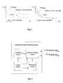
- Figure 1 illustrates two graphs that show strength duration curves in two different situations.
- Figure 2 is a block diagram illustrating a preferred embodiment of the present invention.
- the present invention concerns an implantable heart stimulating device, in particular a biventricular pacemaker system, where LV stimulation is performed between the LV-tip (cathode) and the RV-ring (anode).
- a small diameter, often unipolar, left ventricular (LV), coronary sinus (CS) electrode lead and a bipolar right ventricular (RV) endocardial electrode lead are preferably employed to provide left and right heart chamber pacing/sensing electrodes.
- the LV CS lead is advanced through the superior vena cava, the right atrium, the ostium of the coronary sinus (CS), the CS, and into the coronary vein descending from the CS to locate the LV active pace/sense electrode at a desired LV pace/sense site.
- the RV electrode lead is advanced into the RV chamber to locate RV tip and ring electrodes therein.
- a requirement that makes non-simultaneous biventricular pacing and VV-delay optimization is that no anodal ring stimulation capturing the RV-ring is present.
- the LV pulse width is preferably adjusted so that LV-tip capture is obtained while anodal ring stimulation is not capturing the RV. This is schematically illustrated in figure 1 (see area "X" in figure 1 ).
- Figure 1 illustrates examples of unipolar strength-duration curves at anodal RV ring stimulation and cathodal LV tip stimulation.
- the Y-axis designates the stimulation threshold in volts, i.e. the amplitude of a stimulation pulse, and the X-axis designates the pulse width.
- the right graph illustrates a situation where the two strength-duration curves are close to each other or even cross.
- area “Y” there is capture in the right ventricle but loss in the left ventricle.
- "Y” it is not possible to only get capture in the left ventricle.
- RV and LV are close to each other ( figure 1 , right graph), it is, however, recommended not to use the RV ring as anode for the stimulation current. Instead the RV-ring in combination with the SVC-coil, RV-coil and/or the case is better to use. This is in accordance with a second preferred embodiment of the present invention, which will be further discussed below.
- US-6,687,545 disclose a device where anodal stimulation is monitored by measuring the delay of the evoked response at the ring electrode, and if no delay is detected anodal stimulation is considered detected.
- RV-stimulation Normally the left ventricle is stimulated before the right ventricle. Beat-to-beat capture verification is performed in the right ventricle being the last ventricle. If the system cannot detect capture in the last ventricle, despite the threshold searches postulate that it should be, it is an indication of anodal stimulation in the right ventricle before the actual RV stimulation. The reason for non-capture is that the myocardium in the right ventricle is refractory at the time of the RV stimulation due to bifocal capture at the time of the first stimulation in the left ventricle.
- RV-stimulation normally the left ventricle is stimulated before the right ventricle. If the VV-delay is short an anodal RV-ring capture may be detected as capture from a stimulation pulse applied to the RV-ring. In this case the right ventricle heart tissue is refractory resulting in non-capture irrespectively of the level of the stimulation amplitude applied to the RV-ring electrode, because it is the LV stimulation pulse that stimulates the RV. Thus, if we still get capture in the RV (being the last ventricle) with zero pulse amplitude at the RV ring electrode it is an indication of anodal RV stimulation.
- the threshold searches of the electrodes may be performed by temporarily switch mode to RV pacing (LV off). Then a threshold search with an anodal pacing pulse (e.g. the pacing may be between the case (negative) and the RV-ring (positive)) which will reveal the actual anodal threshold of the RV-ring. The same procedure is then performed in the LV (RV off) but with cathodic pacing pulse. If the two threshold values are close or even lower in the RV it is clear that it is difficult to find a stimulation pulse characteristic that avoids anodal stimulation of the RV-ring, instead other combinations of indifferent electrodes may be used according to the second preferred embodiment.
- Still another way to detect anodal RV-ring stimulation is to analyze the IEGM in the RV at biventricular stimulation with the LV before the RV.
- ER evoked response
- An obvious limitation with this method is that the RV threshold must be higher than the LV threshold.
- threshold searches are performed at different pulse widths to find the optimal pulse width that gives the highest difference in cathodal LV threshold and anodal RV threshold. In this point the anodal RV strength duration curve must be above the cathodal LV threshold.
- the implantable heart stimulating device comprises a left ventricular (LV) coronary sinus (CS) electrode lead at least provided with a tip electrode, a right ventricular (RV) electrode lead at least provided with a ring electrode, a pulse generating means connected to the leads and adapted to apply a stimulation pulse between the tip electrode and ring electrode, wherein the tip electrode being the cathode.
- the device also comprises a monitoring means adapted to monitor for and detect anodal stimulation at the right ventricular ring electrode subsequent to a stimulation.
- the monitoring means includes features necessary to perform normal evoked response detection. If anodal stimulation at the right ventricular ring electrode is detected a threshold search is performed by varying the pulse width and/or pulse amplitude in order to identify stimulation pulse characteristics that avoid anodal stimulation at the ring electrode.
- the device comprises a control means connected to the monitoring means and to the pulse generating means.
- the control means In response of a detected anodal stimulation the control means generates and applies control signals to the pulse generating means in order to initiate the threshold search.
- strength duration curves of the electrode(s) may be established and used to identify the stimulation pulse characteristics that avoid anodal stimulation at the ring electrode.
- the identified stimulation pulse characteristics are chosen such that they are above the strength duration curve of the LV CS tip electrode but below the strength duration curve of the RV ring electrode, when inserted into a strength duration curve diagram (cf. the "X"-area in the left graph of figure 1 ).
- a change or a proposal for a change is made of the anode for LV pacing from RV-ring to another electrode configuration.
- This electrode configuration includes the RV-ring and one or many of the case, RA-ring, LV-ring, RV-coil or SVC-coil (if available).
- the implantable heart stimulating device comprises a left ventricular (LV) coronary sinus (CS) electrode lead at least provided with a tip electrode, a right ventricular (RV) electrode lead at least provided with a ring electrode, a pulse generating means connected to the leads and adapted to apply a stimulation pulse between the tip electrode and ring electrode, wherein the tip electrode being the cathode.
- the device comprises a monitoring means adapted to monitor for and detect anodal stimulation at said right ventricular ring electrode subsequent to a stimulation.
- the monitoring means includes features necessary to perform normal evoked response detection. If anodal stimulation at the right ventricular ring electrode is detected, at least one further electrode is arranged to function as indifferent electrode together with the ring electrode. This is achieved by electrically connecting the ring electrode to the at least one further electrode by a coupling means in response of control signals generated by a control means.
- the further electrode is arranged at any of the leads and may e.g. be a coil electrode at the right or left ventricular electrode lead and/or at the housing of the device.
- the monitoring of anodal stimulation may e.g. be performed by measuring the delay of the evoked response at the ring electrode, and if no delay is detected anodal stimulation is considered detected. This is further described above in connection with the prior art document US-6,687,545 .
- the RV stimulation can just be turned off. Instead every ventricular stimulation will stimulate both LV and RV simultaneously which saves energy. Evoked response detectors are still active in both ventricles to verify capture. If a loss occurs in either ventricle the pacing amplitude is increased as usual. If that does not help to get anodal capture in RV the system switches the pacing mode to dual ventricular pulse (preferably not with RV ring as anode).
- the actions mentioned above can either be performed automatically by the device or be performed by the healthcare personnel at next follow up at the healthcare centre.
- the alert to change setting may be communicated to the physician via the programmer.
Landscapes
- Health & Medical Sciences (AREA)
- Cardiology (AREA)
- Heart & Thoracic Surgery (AREA)
- Life Sciences & Earth Sciences (AREA)
- Engineering & Computer Science (AREA)
- Biomedical Technology (AREA)
- Nuclear Medicine, Radiotherapy & Molecular Imaging (AREA)
- Radiology & Medical Imaging (AREA)
- Animal Behavior & Ethology (AREA)
- General Health & Medical Sciences (AREA)
- Public Health (AREA)
- Veterinary Medicine (AREA)
- Physiology (AREA)
- Biophysics (AREA)
- Electrotherapy Devices (AREA)
Applications Claiming Priority (2)
| Application Number | Priority Date | Filing Date | Title |
|---|---|---|---|
| PCT/SE2006/000119 WO2007086782A1 (en) | 2006-01-26 | 2006-01-26 | Anodal capture |
| EP06701334A EP1981587A1 (de) | 2006-01-26 | 2006-01-26 | Anodische stimulation (capture) |
Related Parent Applications (2)
| Application Number | Title | Priority Date | Filing Date |
|---|---|---|---|
| EP06701334A Division EP1981587A1 (de) | 2006-01-26 | 2006-01-26 | Anodische stimulation (capture) |
| EP06701334.2 Division | 2006-01-26 |
Publications (2)
| Publication Number | Publication Date |
|---|---|
| EP2092959A1 true EP2092959A1 (de) | 2009-08-26 |
| EP2092959B1 EP2092959B1 (de) | 2012-06-27 |
Family
ID=38309483
Family Applications (2)
| Application Number | Title | Priority Date | Filing Date |
|---|---|---|---|
| EP09159796A Expired - Lifetime EP2092959B1 (de) | 2006-01-26 | 2006-01-26 | Anodische Erfassung |
| EP06701334A Withdrawn EP1981587A1 (de) | 2006-01-26 | 2006-01-26 | Anodische stimulation (capture) |
Family Applications After (1)
| Application Number | Title | Priority Date | Filing Date |
|---|---|---|---|
| EP06701334A Withdrawn EP1981587A1 (de) | 2006-01-26 | 2006-01-26 | Anodische stimulation (capture) |
Country Status (3)
| Country | Link |
|---|---|
| US (1) | US20090030470A1 (de) |
| EP (2) | EP2092959B1 (de) |
| WO (1) | WO2007086782A1 (de) |
Families Citing this family (18)
| Publication number | Priority date | Publication date | Assignee | Title |
|---|---|---|---|---|
| US20060247693A1 (en) | 2005-04-28 | 2006-11-02 | Yanting Dong | Non-captured intrinsic discrimination in cardiac pacing response classification |
| US7774064B2 (en) | 2003-12-12 | 2010-08-10 | Cardiac Pacemakers, Inc. | Cardiac response classification using retriggerable classification windows |
| US7392086B2 (en) * | 2005-04-26 | 2008-06-24 | Cardiac Pacemakers, Inc. | Implantable cardiac device and method for reduced phrenic nerve stimulation |
| US8209013B2 (en) * | 2006-09-14 | 2012-06-26 | Cardiac Pacemakers, Inc. | Therapeutic electrical stimulation that avoids undesirable activation |
| US9037239B2 (en) | 2007-08-07 | 2015-05-19 | Cardiac Pacemakers, Inc. | Method and apparatus to perform electrode combination selection |
| US8265736B2 (en) | 2007-08-07 | 2012-09-11 | Cardiac Pacemakers, Inc. | Method and apparatus to perform electrode combination selection |
| US9415226B1 (en) | 2007-12-20 | 2016-08-16 | Pacesetter, Inc. | Method and apparatus with anodal capture monitoring |
| CN101939051B (zh) | 2008-02-14 | 2013-07-10 | 心脏起搏器公司 | 用于膈刺激检测的方法和装置 |
| US8401639B2 (en) * | 2009-04-13 | 2013-03-19 | Cardiac Pacemakers, Inc. | Anodal stimulation detection and avoidance |
| US8126546B2 (en) | 2009-06-30 | 2012-02-28 | Pacesetter, Inc. | Anodal excitation of tissue |
| JP5736464B2 (ja) * | 2010-11-23 | 2015-06-17 | カーディアック ペースメイカーズ, インコーポレイテッド | 心臓陽極性電気刺激検出 |
| US8626291B2 (en) | 2011-07-28 | 2014-01-07 | Medtronic, Inc. | Method for discriminating anodal and cathodal capture |
| US8527050B2 (en) | 2011-07-28 | 2013-09-03 | Medtronic, Inc. | Method for discriminating anodal and cathodal capture |
| US9199087B2 (en) | 2011-11-21 | 2015-12-01 | Medtronic, Inc. | Apparatus and method for selecting a preferred pacing vector in a cardiac resynchronization device |
| US9037238B2 (en) | 2011-11-21 | 2015-05-19 | Michael C. Soldner | Method for efficient delivery of dual site pacing |
| US8682433B2 (en) | 2011-11-21 | 2014-03-25 | Medtronic, Inc. | Method for efficient delivery of dual site pacing |
| FR2999440A1 (fr) * | 2012-12-14 | 2014-06-20 | Sorin Crm Sas | Dispositif medical implantable actif de type stimulateur cardiaque a detection de stimulation anodique par analyse de vectogramme |
| US9878164B2 (en) | 2013-10-04 | 2018-01-30 | Cardiac Pacemakers, Inc. | Cardiac pacing with anodal stimulation detection |
Citations (6)
| Publication number | Priority date | Publication date | Assignee | Title |
|---|---|---|---|---|
| US20020082651A1 (en) * | 2000-12-26 | 2002-06-27 | Stahmann Jeffrey E. | Pacing and sensing vectors |
| US6421564B1 (en) | 1999-11-12 | 2002-07-16 | Medtronic, Inc. | Bi-chamber cardiac pacing system employing unipolar left heart chamber lead in combination with bipolar right chamber lead |
| US6611712B2 (en) | 2000-12-26 | 2003-08-26 | Cardiac Pacemakers, Inc. | Apparatus and method for testing and adjusting a bipolar stimulation configuration |
| US6687545B1 (en) | 2001-10-23 | 2004-02-03 | Pacesetter, Inc. | Cardiac stimulation system and method for performing automatic capture verification during bipolar stimulation |
| US7389140B1 (en) * | 2004-06-16 | 2008-06-17 | Kroll Mark W | Adjustment of stimulation current path |
| WO2009020639A1 (en) * | 2007-08-07 | 2009-02-12 | Cardiac Pacemakers, Inc. | Method and apparatus to perform electrode combination selection |
Family Cites Families (5)
| Publication number | Priority date | Publication date | Assignee | Title |
|---|---|---|---|---|
| US5601615A (en) * | 1994-08-16 | 1997-02-11 | Medtronic, Inc. | Atrial and ventricular capture detection and threshold-seeking pacemaker |
| US5713933A (en) * | 1994-11-30 | 1998-02-03 | Medtronic, Inc. | Method and apparatus for automatic pacing threshold determination |
| US6337995B1 (en) * | 1996-08-19 | 2002-01-08 | Mower Chf Treatment Irrevocable Trust | Atrial sensing and multiple site stimulation as intervention for atrial fibrillation |
| US5814079A (en) * | 1996-10-04 | 1998-09-29 | Medtronic, Inc. | Cardiac arrhythmia management by application of adnodal stimulation for hyperpolarization of myocardial cells |
| EP1191714B1 (de) * | 2000-09-22 | 2003-01-29 | Alcatel Alsthom Compagnie Generale D'electricite | Verfahren zur Überwachung eines optischen Wellenleiters, Überwachungsvorrichtung und Überwachungseinheit für das Verfahren |
-
2006
- 2006-01-26 EP EP09159796A patent/EP2092959B1/de not_active Expired - Lifetime
- 2006-01-26 US US12/160,849 patent/US20090030470A1/en not_active Abandoned
- 2006-01-26 EP EP06701334A patent/EP1981587A1/de not_active Withdrawn
- 2006-01-26 WO PCT/SE2006/000119 patent/WO2007086782A1/en not_active Ceased
Patent Citations (6)
| Publication number | Priority date | Publication date | Assignee | Title |
|---|---|---|---|---|
| US6421564B1 (en) | 1999-11-12 | 2002-07-16 | Medtronic, Inc. | Bi-chamber cardiac pacing system employing unipolar left heart chamber lead in combination with bipolar right chamber lead |
| US20020082651A1 (en) * | 2000-12-26 | 2002-06-27 | Stahmann Jeffrey E. | Pacing and sensing vectors |
| US6611712B2 (en) | 2000-12-26 | 2003-08-26 | Cardiac Pacemakers, Inc. | Apparatus and method for testing and adjusting a bipolar stimulation configuration |
| US6687545B1 (en) | 2001-10-23 | 2004-02-03 | Pacesetter, Inc. | Cardiac stimulation system and method for performing automatic capture verification during bipolar stimulation |
| US7389140B1 (en) * | 2004-06-16 | 2008-06-17 | Kroll Mark W | Adjustment of stimulation current path |
| WO2009020639A1 (en) * | 2007-08-07 | 2009-02-12 | Cardiac Pacemakers, Inc. | Method and apparatus to perform electrode combination selection |
Non-Patent Citations (1)
| Title |
|---|
| THIBAULT B ET AL: "Anodal right ventricular capture during left ventricular stimulation in CRT-implantable cardioverter defibrillators", PACE - PACING AND CLINICAL ELECTROPHYSIOLOGY, BLACWELL FUTURA PUBLISHING, MALDEN, MA, US, vol. 28, no. 7, 1 July 2005 (2005-07-01), pages 613 - 619, XP003000370, ISSN: 0147-8389 * |
Also Published As
| Publication number | Publication date |
|---|---|
| WO2007086782A1 (en) | 2007-08-02 |
| US20090030470A1 (en) | 2009-01-29 |
| EP2092959B1 (de) | 2012-06-27 |
| EP1981587A1 (de) | 2008-10-22 |
Similar Documents
| Publication | Publication Date | Title |
|---|---|---|
| EP2142252B1 (de) | Implantierbares herzstimulationsgerät | |
| US8527050B2 (en) | Method for discriminating anodal and cathodal capture | |
| US6611712B2 (en) | Apparatus and method for testing and adjusting a bipolar stimulation configuration | |
| EP2092959B1 (de) | Anodische Erfassung | |
| US7412287B2 (en) | Automatic sensing vector selection for morphology-based capture verification | |
| US20040260351A1 (en) | Evoked response detector | |
| WO2004050179A1 (en) | Determining relative depolarization at multiple cardiac sites | |
| US6928326B1 (en) | Diagnosis of fusion or pseudofusion | |
| US8290590B2 (en) | Dynamic morphology based atrial automatic threshold | |
| EP2736590B1 (de) | Verfahren zur unterscheidung von anodischer und kathodischer stimulation | |
| EP2654888B1 (de) | Rateninitialisierung und overdrive-schrittsteuerung zur prüfung der erfassungsschwelle | |
| US10441797B2 (en) | Implantable cardiac resynchronizer with biventricular pacing and detection of loss of capture and anodal stimulation | |
| JPH09206387A (ja) | 心臓刺激装置 | |
| US20080119902A1 (en) | Methods and systems for management of atrial retrograde conduction and pacemaker mediated tachyarrhythmia threshold | |
| US6954671B1 (en) | Implantable heart stimulator or which identifies the origin of heart signals | |
| US8019415B2 (en) | Cardiac stimulator with stimulation success monitoring |
Legal Events
| Date | Code | Title | Description |
|---|---|---|---|
| PUAI | Public reference made under article 153(3) epc to a published international application that has entered the european phase |
Free format text: ORIGINAL CODE: 0009012 |
|
| AC | Divisional application: reference to earlier application |
Ref document number: 1981587 Country of ref document: EP Kind code of ref document: P |
|
| AK | Designated contracting states |
Kind code of ref document: A1 Designated state(s): AT BE BG CH CY CZ DE DK EE ES FI FR GB GR HU IE IS IT LI LT LU LV MC NL PL PT RO SE SI SK TR |
|
| 17P | Request for examination filed |
Effective date: 20100226 |
|
| GRAP | Despatch of communication of intention to grant a patent |
Free format text: ORIGINAL CODE: EPIDOSNIGR1 |
|
| GRAS | Grant fee paid |
Free format text: ORIGINAL CODE: EPIDOSNIGR3 |
|
| GRAA | (expected) grant |
Free format text: ORIGINAL CODE: 0009210 |
|
| AC | Divisional application: reference to earlier application |
Ref document number: 1981587 Country of ref document: EP Kind code of ref document: P |
|
| AK | Designated contracting states |
Kind code of ref document: B1 Designated state(s): AT BE BG CH CY CZ DE DK EE ES FI FR GB GR HU IE IS IT LI LT LU LV MC NL PL PT RO SE SI SK TR |
|
| REG | Reference to a national code |
Ref country code: GB Ref legal event code: FG4D |
|
| REG | Reference to a national code |
Ref country code: CH Ref legal event code: EP |
|
| REG | Reference to a national code |
Ref country code: AT Ref legal event code: REF Ref document number: 563813 Country of ref document: AT Kind code of ref document: T Effective date: 20120715 |
|
| REG | Reference to a national code |
Ref country code: IE Ref legal event code: FG4D |
|
| REG | Reference to a national code |
Ref country code: DE Ref legal event code: R096 Ref document number: 602006030506 Country of ref document: DE Effective date: 20120823 |
|
| PG25 | Lapsed in a contracting state [announced via postgrant information from national office to epo] |
Ref country code: SE Free format text: LAPSE BECAUSE OF FAILURE TO SUBMIT A TRANSLATION OF THE DESCRIPTION OR TO PAY THE FEE WITHIN THE PRESCRIBED TIME-LIMIT Effective date: 20120627 Ref country code: FI Free format text: LAPSE BECAUSE OF FAILURE TO SUBMIT A TRANSLATION OF THE DESCRIPTION OR TO PAY THE FEE WITHIN THE PRESCRIBED TIME-LIMIT Effective date: 20120627 Ref country code: LT Free format text: LAPSE BECAUSE OF FAILURE TO SUBMIT A TRANSLATION OF THE DESCRIPTION OR TO PAY THE FEE WITHIN THE PRESCRIBED TIME-LIMIT Effective date: 20120627 |
|
| REG | Reference to a national code |
Ref country code: NL Ref legal event code: VDEP Effective date: 20120627 |
|
| REG | Reference to a national code |
Ref country code: AT Ref legal event code: MK05 Ref document number: 563813 Country of ref document: AT Kind code of ref document: T Effective date: 20120627 |
|
| REG | Reference to a national code |
Ref country code: LT Ref legal event code: MG4D Effective date: 20120606 |
|
| PG25 | Lapsed in a contracting state [announced via postgrant information from national office to epo] |
Ref country code: SI Free format text: LAPSE BECAUSE OF FAILURE TO SUBMIT A TRANSLATION OF THE DESCRIPTION OR TO PAY THE FEE WITHIN THE PRESCRIBED TIME-LIMIT Effective date: 20120627 Ref country code: LV Free format text: LAPSE BECAUSE OF FAILURE TO SUBMIT A TRANSLATION OF THE DESCRIPTION OR TO PAY THE FEE WITHIN THE PRESCRIBED TIME-LIMIT Effective date: 20120627 Ref country code: GR Free format text: LAPSE BECAUSE OF FAILURE TO SUBMIT A TRANSLATION OF THE DESCRIPTION OR TO PAY THE FEE WITHIN THE PRESCRIBED TIME-LIMIT Effective date: 20120928 |
|
| PG25 | Lapsed in a contracting state [announced via postgrant information from national office to epo] |
Ref country code: AT Free format text: LAPSE BECAUSE OF FAILURE TO SUBMIT A TRANSLATION OF THE DESCRIPTION OR TO PAY THE FEE WITHIN THE PRESCRIBED TIME-LIMIT Effective date: 20120627 Ref country code: SK Free format text: LAPSE BECAUSE OF FAILURE TO SUBMIT A TRANSLATION OF THE DESCRIPTION OR TO PAY THE FEE WITHIN THE PRESCRIBED TIME-LIMIT Effective date: 20120627 Ref country code: CZ Free format text: LAPSE BECAUSE OF FAILURE TO SUBMIT A TRANSLATION OF THE DESCRIPTION OR TO PAY THE FEE WITHIN THE PRESCRIBED TIME-LIMIT Effective date: 20120627 Ref country code: BE Free format text: LAPSE BECAUSE OF FAILURE TO SUBMIT A TRANSLATION OF THE DESCRIPTION OR TO PAY THE FEE WITHIN THE PRESCRIBED TIME-LIMIT Effective date: 20120627 Ref country code: IS Free format text: LAPSE BECAUSE OF FAILURE TO SUBMIT A TRANSLATION OF THE DESCRIPTION OR TO PAY THE FEE WITHIN THE PRESCRIBED TIME-LIMIT Effective date: 20121027 Ref country code: EE Free format text: LAPSE BECAUSE OF FAILURE TO SUBMIT A TRANSLATION OF THE DESCRIPTION OR TO PAY THE FEE WITHIN THE PRESCRIBED TIME-LIMIT Effective date: 20120627 Ref country code: RO Free format text: LAPSE BECAUSE OF FAILURE TO SUBMIT A TRANSLATION OF THE DESCRIPTION OR TO PAY THE FEE WITHIN THE PRESCRIBED TIME-LIMIT Effective date: 20120627 Ref country code: CY Free format text: LAPSE BECAUSE OF FAILURE TO SUBMIT A TRANSLATION OF THE DESCRIPTION OR TO PAY THE FEE WITHIN THE PRESCRIBED TIME-LIMIT Effective date: 20120627 |
|
| PG25 | Lapsed in a contracting state [announced via postgrant information from national office to epo] |
Ref country code: IT Free format text: LAPSE BECAUSE OF FAILURE TO SUBMIT A TRANSLATION OF THE DESCRIPTION OR TO PAY THE FEE WITHIN THE PRESCRIBED TIME-LIMIT Effective date: 20120627 Ref country code: PT Free format text: LAPSE BECAUSE OF FAILURE TO SUBMIT A TRANSLATION OF THE DESCRIPTION OR TO PAY THE FEE WITHIN THE PRESCRIBED TIME-LIMIT Effective date: 20121029 Ref country code: PL Free format text: LAPSE BECAUSE OF FAILURE TO SUBMIT A TRANSLATION OF THE DESCRIPTION OR TO PAY THE FEE WITHIN THE PRESCRIBED TIME-LIMIT Effective date: 20120627 |
|
| PG25 | Lapsed in a contracting state [announced via postgrant information from national office to epo] |
Ref country code: NL Free format text: LAPSE BECAUSE OF FAILURE TO SUBMIT A TRANSLATION OF THE DESCRIPTION OR TO PAY THE FEE WITHIN THE PRESCRIBED TIME-LIMIT Effective date: 20120627 |
|
| PG25 | Lapsed in a contracting state [announced via postgrant information from national office to epo] |
Ref country code: DK Free format text: LAPSE BECAUSE OF FAILURE TO SUBMIT A TRANSLATION OF THE DESCRIPTION OR TO PAY THE FEE WITHIN THE PRESCRIBED TIME-LIMIT Effective date: 20120627 Ref country code: ES Free format text: LAPSE BECAUSE OF FAILURE TO SUBMIT A TRANSLATION OF THE DESCRIPTION OR TO PAY THE FEE WITHIN THE PRESCRIBED TIME-LIMIT Effective date: 20121008 |
|
| PLBE | No opposition filed within time limit |
Free format text: ORIGINAL CODE: 0009261 |
|
| STAA | Information on the status of an ep patent application or granted ep patent |
Free format text: STATUS: NO OPPOSITION FILED WITHIN TIME LIMIT |
|
| 26N | No opposition filed |
Effective date: 20130328 |
|
| REG | Reference to a national code |
Ref country code: DE Ref legal event code: R097 Ref document number: 602006030506 Country of ref document: DE Effective date: 20130328 |
|
| PG25 | Lapsed in a contracting state [announced via postgrant information from national office to epo] |
Ref country code: BG Free format text: LAPSE BECAUSE OF FAILURE TO SUBMIT A TRANSLATION OF THE DESCRIPTION OR TO PAY THE FEE WITHIN THE PRESCRIBED TIME-LIMIT Effective date: 20120927 |
|
| PG25 | Lapsed in a contracting state [announced via postgrant information from national office to epo] |
Ref country code: MC Free format text: LAPSE BECAUSE OF NON-PAYMENT OF DUE FEES Effective date: 20130131 |
|
| REG | Reference to a national code |
Ref country code: CH Ref legal event code: PL |
|
| GBPC | Gb: european patent ceased through non-payment of renewal fee |
Effective date: 20130126 |
|
| REG | Reference to a national code |
Ref country code: IE Ref legal event code: MM4A |
|
| PG25 | Lapsed in a contracting state [announced via postgrant information from national office to epo] |
Ref country code: LI Free format text: LAPSE BECAUSE OF NON-PAYMENT OF DUE FEES Effective date: 20130131 Ref country code: CH Free format text: LAPSE BECAUSE OF NON-PAYMENT OF DUE FEES Effective date: 20130131 |
|
| PG25 | Lapsed in a contracting state [announced via postgrant information from national office to epo] |
Ref country code: GB Free format text: LAPSE BECAUSE OF NON-PAYMENT OF DUE FEES Effective date: 20130126 |
|
| PG25 | Lapsed in a contracting state [announced via postgrant information from national office to epo] |
Ref country code: IE Free format text: LAPSE BECAUSE OF NON-PAYMENT OF DUE FEES Effective date: 20130126 |
|
| PG25 | Lapsed in a contracting state [announced via postgrant information from national office to epo] |
Ref country code: TR Free format text: LAPSE BECAUSE OF FAILURE TO SUBMIT A TRANSLATION OF THE DESCRIPTION OR TO PAY THE FEE WITHIN THE PRESCRIBED TIME-LIMIT Effective date: 20120627 |
|
| PG25 | Lapsed in a contracting state [announced via postgrant information from national office to epo] |
Ref country code: HU Free format text: LAPSE BECAUSE OF FAILURE TO SUBMIT A TRANSLATION OF THE DESCRIPTION OR TO PAY THE FEE WITHIN THE PRESCRIBED TIME-LIMIT; INVALID AB INITIO Effective date: 20060126 Ref country code: LU Free format text: LAPSE BECAUSE OF NON-PAYMENT OF DUE FEES Effective date: 20130126 |
|
| REG | Reference to a national code |
Ref country code: FR Ref legal event code: PLFP Year of fee payment: 11 |
|
| REG | Reference to a national code |
Ref country code: FR Ref legal event code: PLFP Year of fee payment: 12 |
|
| REG | Reference to a national code |
Ref country code: FR Ref legal event code: PLFP Year of fee payment: 13 |
|
| PGFP | Annual fee paid to national office [announced via postgrant information from national office to epo] |
Ref country code: FR Payment date: 20181221 Year of fee payment: 14 |
|
| PGFP | Annual fee paid to national office [announced via postgrant information from national office to epo] |
Ref country code: DE Payment date: 20181219 Year of fee payment: 14 |
|
| REG | Reference to a national code |
Ref country code: DE Ref legal event code: R119 Ref document number: 602006030506 Country of ref document: DE |
|
| PG25 | Lapsed in a contracting state [announced via postgrant information from national office to epo] |
Ref country code: DE Free format text: LAPSE BECAUSE OF NON-PAYMENT OF DUE FEES Effective date: 20200801 Ref country code: FR Free format text: LAPSE BECAUSE OF NON-PAYMENT OF DUE FEES Effective date: 20200131 |
|
| P01 | Opt-out of the competence of the unified patent court (upc) registered |
Effective date: 20230602 |