EP2092983B1 - Zentrifugaldehydrator - Google Patents
Zentrifugaldehydrator Download PDFInfo
- Publication number
- EP2092983B1 EP2092983B1 EP09002186.6A EP09002186A EP2092983B1 EP 2092983 B1 EP2092983 B1 EP 2092983B1 EP 09002186 A EP09002186 A EP 09002186A EP 2092983 B1 EP2092983 B1 EP 2092983B1
- Authority
- EP
- European Patent Office
- Prior art keywords
- sludge
- filter
- centrifugal dehydrator
- hollow shaft
- rotary drum
- Prior art date
- Legal status (The legal status is an assumption and is not a legal conclusion. Google has not performed a legal analysis and makes no representation as to the accuracy of the status listed.)
- Not-in-force
Links
- 239000010802 sludge Substances 0.000 claims description 78
- 238000004140 cleaning Methods 0.000 description 37
- 239000000463 material Substances 0.000 description 36
- XLYOFNOQVPJJNP-UHFFFAOYSA-N water Substances O XLYOFNOQVPJJNP-UHFFFAOYSA-N 0.000 description 20
- 230000018044 dehydration Effects 0.000 description 10
- 238000006297 dehydration reaction Methods 0.000 description 10
- 239000010865 sewage Substances 0.000 description 8
- 238000005192 partition Methods 0.000 description 6
- 230000002093 peripheral effect Effects 0.000 description 6
- 238000000034 method Methods 0.000 description 5
- 230000000694 effects Effects 0.000 description 4
- 239000007787 solid Substances 0.000 description 4
- 239000002184 metal Substances 0.000 description 3
- 230000004323 axial length Effects 0.000 description 2
- 230000003247 decreasing effect Effects 0.000 description 2
- 239000011796 hollow space material Substances 0.000 description 2
- 238000000926 separation method Methods 0.000 description 2
- 238000005119 centrifugation Methods 0.000 description 1
- 239000013013 elastic material Substances 0.000 description 1
- 230000005484 gravity Effects 0.000 description 1
- 239000010842 industrial wastewater Substances 0.000 description 1
- 239000008235 industrial water Substances 0.000 description 1
- 239000007788 liquid Substances 0.000 description 1
- 238000004080 punching Methods 0.000 description 1
- 238000007790 scraping Methods 0.000 description 1
- 238000004062 sedimentation Methods 0.000 description 1
- 238000004088 simulation Methods 0.000 description 1
- 239000008399 tap water Substances 0.000 description 1
- 235000020679 tap water Nutrition 0.000 description 1
Images


Classifications
-
- B—PERFORMING OPERATIONS; TRANSPORTING
- B04—CENTRIFUGAL APPARATUS OR MACHINES FOR CARRYING-OUT PHYSICAL OR CHEMICAL PROCESSES
- B04B—CENTRIFUGES
- B04B3/00—Centrifuges with rotary bowls in which solid particles or bodies become separated by centrifugal force and simultaneous sifting or filtering
- B04B3/04—Centrifuges with rotary bowls in which solid particles or bodies become separated by centrifugal force and simultaneous sifting or filtering discharging solid particles from the bowl by a conveying screw coaxial with the bowl axis and rotating relatively to the bowl
Definitions
- the present invention relates to a centrifugal dehydrator and more particularly to a centrifugal dehydrator which dehydrates sludge generated in the process of biological treatment of industrial waste water or sewage flowing in a public sewage system and produces concentrated sludge.
- the sludge generated at the final step is dehydrated in order to decrease its volume to make its transportation or incineration easy.
- the moisture content of sludge before dehydration is 95% or more.
- Transportation of sludge with a high moisture content virtually means transportation of water, resulting in a high transportation cost.
- transportation and disposal of such sludge are troublesome. For this reason, the moisture content of sludge is often reduced to approximately 80% or less by dehydrating it mechanically before transportation.
- JP-A No. HEI8 (1996)-294644 .
- the centrifugal dehydrator described in this gazette has a spiral screw impeller blade fitted to a rotary shaft.
- Scrapers made of elastic material are attached to the peripheral surfaces of the screw impeller blade and the scrapers can move radially to scrape off cakes as the rotary shaft rotates.
- centrifugal dehydrators in the related art, sludge is put in a rotary drum and the drum is rotated. Then, the solid content and moisture of the sludge are separated by centrifugal sedimentation utilizing the difference in specific gravity inside the rotary drum. In the separation process, the sludge's solid content is collected on the peripheral side of the rotary drum while its moisture is collected inside it. The sludge's solid content separated and accumulated on the peripheral surface is forced out of the rotary drum by a conveyance mechanism such as a screw attached to the rotary shaft. On the other hand, the collected moisture is discharged from the drum through a barrage installed adjacently inside the drum.
- centrifugal dehydrators require considerable power consumption because a large volume of sludge and moisture are rotated inside the rotary drum.
- the major reason for considerable power consumption is that as the rotary drum rotates, sludge turbulence occurs inside the drum and the kinetic energy of this sludge turbulence is wastefully dissipated.
- the axial length of the rotary drum must be long enough to allow the sludge to stay inside the drum for a specified time period and consequently a large volume of sludge is held inside the drum, resulting in considerable power consumption.
- the centrifugal dehydrator size should be larger.
- the present invention has been made in view of the above problem of the related art and an object thereof is to reduce the energy required for dehydrating operation of a centrifugal dehydrator in order to contribute to energy saving in a sewage disposal plant. Another object of the present invention is to realize a lighter, smaller centrifugal dehydrator.
- a centrifugal dehydrator which includes: a hollow shaft having a cavity in which sludge can flow and a discharge port for discharge of sludge from the cavity; a support means which supports the hollow shaft rotatably; a discharge means which is provided on the hollow shaft's outer periphery and can convey sludge in an axial direction; and a drum which is located radially in a more outer position than the discharge means and almost coaxial with the hollow shaft and can rotate at a rotation speed different from the hollow shaft's rotation speed.
- the drum has a filter and many blades spaced at intervals in its circumferential direction on the filter's outside diameter side.
- the blades be forward-oriented with radially outer portions inclined toward the drum's rotation direction and inclination angle ⁇ of the forward-oriented blades be in a range of 135 to 150 degrees as measured from a radial line.
- the filter be produced by making many tiny holes in a thin plate formed into a cylindrical surface and the tiny holes be oblong holes perpendicular to the filter's cylindrical shaft and these tiny holes' longitudinal size be almost equal to inter-blade distance of the many blades.
- the discharge means may be a screw which is spiral and integral with the hollow shaft and may have plural ridges in terms of length. Its axial relative position with respect to the hollow shaft may be variable and a driving means to drive the discharge means axially may be provided.
- the sludge is dehydrated by centrifugal force, so the time for which the sludge stays in the rotary drum is reduced.
- the volume of sludge in the rotary drum is decreased and energy saving is achieved in the centrifugal dehydrator and sewage disposal plant.
- the filter attached to the rotary drum of the centrifugal dehydrator is cleaned and revived with high efficiency, so an energy saving dehydration system is realized and the centrifugal dehydrator can be lighter and smaller.
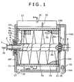
- Fig. 1 is a longitudinal sectional view of a centrifugal dehydrator 100 according to an embodiment.
- the centrifugal dehydrator 100 is designed for use in a sewage disposal plant and uses a horizontal shaft.
- the centrifugal dehydrator 100 is structured as follows.
- a screw (discharge mechanism) 7a having a shape of plural ridges spirally wound therearound, radially stretching as far as a few times the outside diameter of the shaft 2, is integrally formed with the driving shaft 2.
- the hollow portion of the driving shaft 2 has plural material sludge discharge holes 7c spaced at intervals in the circumferential direction. The diameter of each of these holes 7c is large enough to discharge the material sludge into the space formed by the screw 7a and rotary drum 10.
- a hollow sludge supply shaft 1 with a flange is inserted through the left end of the hollow portion of the driving shaft 2.
- the hollow sludge supply shaft 1 is connected with a pump for sludge supply (not shown) which supplies sludge into the hollow sludge supply shaft 1.
- the outer peripheral surface of the hollow shaft 1 and the inner peripheral surface of the driving shaft 2 function as a plain bearing so that the hollow shaft, stationary, can supply sludge even during rotation of the driving shaft 2.
- the driving shaft 2 is rotatably supported by inner plain bearings 3 and 5 at the left and right ends.
- the left inner bearing 3 is held on the inner side of a member 10f.
- the right inner bearing 5 is held on the inner side of a rotary drum driving shaft joint 8 with a flange which is intended to drive the rotary drum 10 which will be detailed later.
- the rotary drum driving shaft joint 8 has a hollow portion to be coupled with the driving shaft 2 and the inner bearing 5 and the small-diameter end portion of the driving shaft 2 are housed in this hollow portion.
- An outer bearing 6 is fitted to the outer surface of the rotary drum driving shaft joint 8.
- the flange of the rotary drum driving shaft joint 8 is connected with a driving machine (not shown) such as a motor.
- the rotary drum 10 is constructed as follows: many tiny holes 9b are made in a metal sheet with a thickness of several millimeters or less; the metal sheet with tiny holes 9b is rounded into a cylinder which serves as a cylindrical filter 9a; many blades 10a are spaced at intervals circumferentially on the outer periphery of the cylindrical filter 9a; and end plates 10c and 10d in the form of rings are attached to both shaft ends of the cylindrical filter 9a; and these are integrally formed to constitute the drum.
- Fig. 1 only shows some tiny holes 9b, tiny holes 9b are distributed all over the surface of the cylindrical filter 9a.
- the tiny holes 9b of the cylindrical filter 9a are oblong in the circumferential direction and mechanically formed by punching or a similar method.
- the left end plate 10c of the rotary drum 10 is coupled through a member 10g.
- the right end plate 10d of the rotary drum 10 is coupled through a member 10h to the rotary drum driving shaft joint 8.
- the blades 10a on the outer periphery of the cylindrical filter 9a are forward-oriented blades with radially outer portions inclined toward the rotary drum's rotation direction.
- the ratio between the inside and outside radial distances of each blade 10a is almost 1 and its length (distance between its inner and outer ends) in the direction of flow is short.
- the width of the inter-blade flow channel 10b as the interval between neighboring blades 10a is equal to or smaller than the length of the blade 10a in the direction of flow (see Fig. 2 ).
- a virtually cylindrical casing 11 covers the rotary drum 10.
- the outer bearing 4 is located on the member 10g constituting the left side of the rotary drum and the outer bearing 6 is located between a partition plate 12 constituting the right side of the casing and the outer surface of the rotary drum driving shaft joint 8.
- the casing 11 is concentric with the rotary drum 10 and a given ring-like space is formed between the inner surface of the casing 11 and the outer surface of the rotary drum 10.
- a discharge channel through which dehydrated sludge is discharged is formed on the right of the partition plate 12 of the casing 11 by members 16b and 16c.
- a water drain port 17 through which water resulting from dehydration by the rotary drum is drained is formed at the bottom of the casing 11 near the left end in the axial direction.
- Fig. 2 is a transverse sectional view taken along the line A-A in Fig. 1 which shows the center of the centrifugal dehydrator 100 in the axial direction.
- the centrifugal dehydrator 100 has cleaning nozzles 13 at the top point and the left and right points approximately 45 degrees away from the top point in the circumferential direction.
- Each cleaning nozzle 13 is formed as an axially long notch in the casing which stretches virtually from the end plate 10C to the end plate 10d in the axial direction.
- the cleaning nozzle 13 has parallel wall portions and tapered portions continuous with the parallel wall portions with a contracted flow path formed therein.
- At least one cleaning water supply hole 14 is provided on the side surface of the cleaning nozzle 13.
- the material sludge 30 which is supplied to the centrifugal dehydrator 100 is prepared by adding flocculant to untreated sludge and includes relatively large flocs (several millimeters).
- the material sludge 30 is introduced through the hollow portion of the hollow shaft 1 into the inside of the centrifugal dehydrator 100 using a pump (not shown).
- the material sludge 30 introduced through the hollow portion of the hollow shaft 1 into the driving shaft 2 of the discharge mechanism is radially ejected through plural supply holes 7c made in the side surface of the hollow portion of the driving shaft 2 by centrifugal force. Then it reaches the filter 9a on the inner surface of the rotary drum 10.
- the material sludge 30 which has reached the filter 9a, its solid content and moisture firmly adhering to it only cannot pass through the tiny holes 9b, which are smaller than the floc size of the material sludge 30, and the rest of the moisture flows through the tiny holes 9b into the inter-blade flow channels 10b formed by the blades 10a on the back side of the filter 9a due to centrifugal force.
- the material sludge 30 is thus dehydrated.
- the rotary drum 10 with the filter 9a rotates and many forward-oriented blades 10a are located on the back side of the filter 9a so that the blades 10a apply a centrifugal force to the moisture contained in the material sludge 30 to enhance the dehydrating effect.
- the outside diameter of the rotary drum 10 is 400 mm
- the inside diameter of the drum 10 is 360 mm
- the rotation speed of the drum 10 is 3000 rpm.
- the speed difference between the inside diameter and outside diameter of the rotary drum 10 corresponds to a pressure generated by the centrifugal force. Since the blades 10a lie on the back side of the filter 9a made of sheet metal, they should have enough supporting strength to ensure that deformation of the filter 9a does not occur and the drum rotates stably even if a large centrifugal force (2000 G in the above case) is applied to the material sludge 30.
- the dehydrated material sludge 30 accumulates on the inner surface of the filter 9a.
- material sludge 30 continues to be supplied through the material sludge discharge holes 7c.
- the driving shaft 2 is rotated to rotate the screw 7a with a rotation speed difference of several revolutions per minute with respect to the rotary drum 10. Since the screw 7a is spiral, as it rotates, its tips touch the dehydrated material sludge 30 accumulated on the filter 9a. The tips scrape off the material sludge 30 and put the material sludge 30 on the surface of the screw 7a to convey it from left to right.
- the dehydrated material sludge 30 accumulated on the inner surface of the rotary drum 10 is conveyed to the partition plate 12 by the screw 7a, which has an outside diameter almost equal to the inside diameter of the filter 9a, and to the discharge port 16 through the discharge channel formed axially outside the partition plate 12.
- the rotary drum 10 always applies a centrifugal force to the material sludge 30, so the material sludge 30 is continuously dehydrated.
- the axial length of the screw 7a is determined so that the moisture content of the dehydrated sludge 33 is below a prescribed level.
- the inner surface of the filter 9a is cleaned by the screw 7a.
- the partition plate 12 is provided to prevent the dehydrated sludge 33 and the water separated from the material sludge 30 from being mixed again.
- cleaning nozzles 13 are provided at plural points in the circumferential direction. Each cleaning nozzle 13 works as follows. As the centrifugal dehydrator 100 is activated, material sludge 30 is accumulated on the inner surface of the filter 9a. When the material sludge 30 accumulated on the filter 9a is conveyed and discharged, the outer peripheral ends of the screw 7a scrape off the material sludge 30. Such scraping tends to cause many tiny holes 9b of the filter 9a to be clogged with material sludge 30. If they should be clogged with material sludge 30, the dehydrating effect would deteriorate; thus the material sludge must be removed in one way or another. In this embodiment, cleaning water 15 is supplied through the cleaning nozzles 13 with ejection holes like slits to clean the tiny holes 9b.
- Fig. 3 the circumferential direction corresponds to the vertical direction and the left-right or horizontal direction corresponds to the radial direction.
- Tap water or industrial water is supplied through the cleaning water supply hole 14 of a cleaning nozzle 13.
- the cleaning water pressure is as low as 0.1 to 0.3 MPa.
- the level of relative velocity W is reduced to approx. 1.9 MPa in terms of pressure. Since this pressure level is far higher than the cleaning water supply pressure (0.1 to 0.3 MPa), it is possible to generate a sufficiently high pressure to remove the material sludge 30 clogging the tiny holes 9b. As apparent from Equation 2, the pressure generated by the cleaning nozzle 13 largely depends on the average circumferential velocity U of the rotary drum 10. Regarding the angle of the relative velocity W, since the blades 10a are forward-oriented ( ⁇ > 90 degrees or more), its angle with respect to the circumferential direction is smaller than the blades 10a's. Therefore, cleaning water collides into the blade surface and reflects on it or turns and goes toward the filter 9a on the inside diameter side. As a result, the water reaches tiny holes 9b of the filter 9a and cleans the filter 9a.
- the slit-like cleaning nozzle 13 guides cleaning water to the tiny hole 9b efficiently.
- three cleaning nozzles 13 are provided in the circumferential direction of the rotary drum 10.
- the number of cleaning nozzles is not limited to 3 and at least one cleaning nozzle is required. If an area where clogging may easily occur is predicted by simulation or the like, cleaning nozzles may be concentrated on that area.
- the cleaning effect is enhanced by increasing the rotation speed of the blades 10a of the rotary drum 10.
- the blade angle is in a range of 135 to 150 degrees.
- the higher the circumferential velocity is, the larger the cleaning effect is.
- the dehydrating efficiency is increased.
- the filter 9a can be cleaned from the outer periphery side by the forward-oriented blades efficiently.
- the machine can operate continuously while performing dehydration and cleaning simultaneously.
- Material sludge 30 is supplied through the hollow material sludge supply shaft 1 and the driving shaft 2 is rotated to activate the screw.
- Cleaning water is supplied to the cleaning nozzles 13.
- the rotation speed of the rotary drum 10 and that of the driving shaft 2 are determined according to the density, viscosity and granularity of the material sludge 30. Therefore, in the centrifugal dehydrator 100, it is desirable that the rotation speed of the rotary drum 10 and that of the driving shaft 2 be both variable.
- the screw 7a which is integral with the driving shaft is used as a mechanism to convey and discharge material sludge 30.
- a means to convey and discharge material sludge 30 is not limited to a screw.
- the discharge mechanism uses a discharge rod 18b driven by a hydraulic unit and a discharge plate 18a attached to the tip of the discharge rod 18b.
- the rotary drum 10, casing 11 and cleaning nozzles 13 are almost the same as in the above first embodiment and their descriptions are omitted here.
- the hollow material sludge supply shaft 1 stretches to the partition plate 12 and the hollow shaft 1 has plural material sludge discharge holes 7c on the cylindrical side surface.
- the discharge rod 18b which has a flange outside the machine, is slidably fitted to the outer periphery of the hollow shaft 1. One end of the discharge rod 18b is outside the machine and the other end is inside the rotary drum 10.
- the discharge plate 18a the outside diameter of which is almost the same as the inside diameter of the rotary drum 10, is located in the discharge rod 18b's portion which lies inside the rotary drum 10.
- the discharge plate 18a has the form of a disc with a trapezoidal cross section in which the central portion is thick in the axial direction.
- a hydraulic unit 18c is connected with the flange of the discharge rod 18b, located outside the machine, so that the discharge rod 18b can move axially by oil pressure.
- the discharge rod 18b and the discharge plate 18a, supported by the bearing 3 reciprocate and intermittently discharge sludge.
- This discharge motion may be made while the rotary drum 10 is rotating or while the rotary drum 10 is slowing down.
- dehydration, sludge discharge and filter cleaning are cyclically repeated until dehydration of the material sludge 30 is finished.
- This operation cycle is controlled by a controller (not shown).
- the volume of material sludge held in the rotary drum is smaller than in conventional machines, leading to energy saving.
- the centrifugal dehydrator can be smaller and lighter.
Landscapes
- Centrifugal Separators (AREA)
- Treatment Of Sludge (AREA)
Claims (5)
- Zentrifugaltrockner, der aufweist:eine Hohlwelle (2), die einen Hohlraum, in dem ein Schlamm (30) fließen kann, und eine Austrittsöffnung (7c) zum Abführen von Schlamm (30) aus dem Hohlraum aufweist,eine Stützeinrichtung (3, 5), die die Hohlwelle drehbar stützt,eine Ableitungseinrichtung (7a), die am äußeren Umfang der Hohlwelle ausgebildet ist und Schlamm in einer axialen Richtung fördern kann, undeine Trommel (10), die radial etwas weiter außen als die Ableitungseinrichtung und in etwa koaxial zur Hohlwelle angeordnet ist und einen Filter (9a) aufweist,dadurch gekennzeichnet, dass die Trommel (10) mit einer von der Drehgeschwindigkeit der Hohlwelle verschiedenen Drehgeschwindigkeit rotieren kann und mehrere Schaufeln (10a) aufweist, die durch Zwischenräume beabstandet in deren Umfangsrichtung an der Seite des Außendurchmessers des Filters angeordnet sind.
- Zentrifugaltrockner nach Anspruch 1, wobei die mehreren Schaufeln (10a) nach vorne ausgerichtet sind, und wobei die äußeren Bereiche zur Rotationsrichtung der Trommel hin geneigt sind und der von einer radialen Linie gemessene Neigungswinkel θ der nach vorne gerichteten Schaufeln (10a) im Bereich von 135 bis 150 Grad liegt.
- Zentrifugaltrockner nach Anspruch 1 oder 2, wobei der Filter (9a) durch Ausbilden von vielen kleinen Löchern (9b) in einer dünnen Platte gefertigt wird, die in eine Zylinderfläche gebogen wird, wobei die kleinen Löcher (9b) senkrecht zur Zylinderwelle verlaufende Längslöcher sind und die Größe der kleinen Löcher in deren Längsrichtung dem Abstand zwischen den vielen Schaufeln (10a) nahezu entspricht.
- Zentrifugaltrockner nach einem der Ansprüche 1 bis 3, worin die Ableitungseinrichtung (7a) eine Schnecke ist, die schraubenförmig und einstückig mit der Hohlwelle ausgebildet ist und in Bezug auf die Länge mehrere Spitzen aufweist.
- Zentrifugaltrockner nach einem der Ansprüche 1 bis 3, worin die axiale Lage der Ableitungseinrichtung relativ zur Hohlwelle variabel ist und eine Antriebseinrichtung (18c) zum axialen Antreiben der Ableitungseinrichtung vorgesehen ist.
Applications Claiming Priority (1)
| Application Number | Priority Date | Filing Date | Title |
|---|---|---|---|
| JP2008040197A JP4924466B2 (ja) | 2008-02-21 | 2008-02-21 | 遠心脱水装置 |
Publications (2)
| Publication Number | Publication Date |
|---|---|
| EP2092983A1 EP2092983A1 (de) | 2009-08-26 |
| EP2092983B1 true EP2092983B1 (de) | 2016-04-27 |
Family
ID=40666834
Family Applications (1)
| Application Number | Title | Priority Date | Filing Date |
|---|---|---|---|
| EP09002186.6A Not-in-force EP2092983B1 (de) | 2008-02-21 | 2009-02-17 | Zentrifugaldehydrator |
Country Status (2)
| Country | Link |
|---|---|
| EP (1) | EP2092983B1 (de) |
| JP (1) | JP4924466B2 (de) |
Cited By (1)
| Publication number | Priority date | Publication date | Assignee | Title |
|---|---|---|---|---|
| US10882058B2 (en) | 2014-06-12 | 2021-01-05 | Gea Mechanical Equipment Gmbh | Solid-jacket screw centrifuge with a solid discharge chamber designed as a drying chamber |
Families Citing this family (6)
| Publication number | Priority date | Publication date | Assignee | Title |
|---|---|---|---|---|
| JP5291575B2 (ja) | 2009-08-26 | 2013-09-18 | 住友重機械工業株式会社 | 軸受構造及び軸受 |
| CN104399599B (zh) * | 2014-11-24 | 2016-08-24 | 浙江荣亿精密机械有限公司 | 一种自动下料出料脱油机 |
| KR101738023B1 (ko) * | 2016-11-07 | 2017-05-22 | 이에스피 주식회사 | 믹서형 조류제거장치 |
| CN108409098A (zh) * | 2018-04-25 | 2018-08-17 | 河南永乐粮油机械有限公司 | 一种多层往复式污泥烘干装置 |
| CN108726843B (zh) * | 2018-06-14 | 2021-01-08 | 宁夏昌昊建设工程有限公司 | 一种水利工程淤泥高效处理设备 |
| CN112221235B (zh) * | 2020-12-16 | 2021-05-07 | 江苏阿兰贝尔环保科技有限公司 | 一种污水净化振筛分离装置 |
Family Cites Families (15)
| Publication number | Priority date | Publication date | Assignee | Title |
|---|---|---|---|---|
| DE1632292A1 (de) * | 1967-06-16 | 1972-02-03 | Ernst Heinkel Maschb Gmbh | Siebzentrifuge |
| DE2604337C3 (de) * | 1976-02-05 | 1979-03-29 | Krauss-Maffei Ag, 8000 Muenchen | Steuerungseinrichtung für die Betätigung des Schubbodens einer Schubzentrifuge |
| JPS5347064A (en) * | 1976-10-12 | 1978-04-27 | Tomiji Nakamura | Continuous centrifugal filter |
| JPS54133674A (en) * | 1978-04-10 | 1979-10-17 | Yoshitaka Shimamoto | Ventilation system centrifugal separator |
| DE8320716U1 (de) * | 1983-07-19 | 1983-11-03 | Pfaff Industriemaschinen Gmbh, 6750 Kaiserslautern | Naehmaschine mit einer hilfsnadel zum drehen des naehgutes |
| GB8625023D0 (en) * | 1986-10-18 | 1986-11-19 | Sp Tyres Uk Ltd | Tyre tread compound |
| DE4013388A1 (de) * | 1990-04-26 | 1991-10-31 | Titus Hans Joachim | Zentrifugen-trockner |
| JPH04281869A (ja) * | 1991-03-08 | 1992-10-07 | Iwatani Raifu Atsupu Kk | 乾燥装置 |
| JPH05305253A (ja) * | 1992-04-28 | 1993-11-19 | Kajima Corp | 土砂分離方法及び装置 |
| JP3291724B2 (ja) | 1995-04-26 | 2002-06-10 | 株式会社石垣 | 遠心脱水機のスクレーパー装置 |
| EP0739702A1 (de) * | 1995-04-27 | 1996-10-30 | Eastman Kodak Company | Verfahren und Vorrichtung zum Formen von dünnwandigen Teilen |
| JP2002273270A (ja) * | 2001-03-22 | 2002-09-24 | Kubota Corp | 遠心分離装置 |
| JP3832330B2 (ja) * | 2001-12-18 | 2006-10-11 | 株式会社石垣 | 外筒回転型濃縮機および汚泥の分離濃縮方法 |
| JP3797551B2 (ja) * | 2002-06-20 | 2006-07-19 | 株式会社石垣 | 回転濃縮機における排出口の調整装置 |
| GB2410709B (en) * | 2004-02-07 | 2007-04-18 | Broadbent & Sons Ltd Thomas | Improving washing of separated solids in solid bowl and screen bowl decanting centrifuges |
-
2008
- 2008-02-21 JP JP2008040197A patent/JP4924466B2/ja not_active Expired - Fee Related
-
2009
- 2009-02-17 EP EP09002186.6A patent/EP2092983B1/de not_active Not-in-force
Cited By (1)
| Publication number | Priority date | Publication date | Assignee | Title |
|---|---|---|---|---|
| US10882058B2 (en) | 2014-06-12 | 2021-01-05 | Gea Mechanical Equipment Gmbh | Solid-jacket screw centrifuge with a solid discharge chamber designed as a drying chamber |
Also Published As
| Publication number | Publication date |
|---|---|
| EP2092983A1 (de) | 2009-08-26 |
| JP2009195829A (ja) | 2009-09-03 |
| JP4924466B2 (ja) | 2012-04-25 |
Similar Documents
| Publication | Publication Date | Title |
|---|---|---|
| EP2092983B1 (de) | Zentrifugaldehydrator | |
| RU2411058C2 (ru) | Устройство разделения твердой и жидкой фазы | |
| US4617010A (en) | Apparatus for the partial dehydration of sludge in the centrifuge field of a solid jacket centrifuge | |
| EP2448648B1 (de) | Verbesserungen in zusammenhang mit einer filtrierungs- und entwässerungsvorrichtung | |
| RU2223151C2 (ru) | Центрифуга с дополнительной секцией ротора | |
| EP3169420B1 (de) | Vertikaler trenner zur behandlung von schlamm | |
| KR100945273B1 (ko) | 고농도 유기폐수의 원심 농축장치 | |
| KR890000146B1 (ko) | 에너지 회수 원심분리기 | |
| JP6753704B2 (ja) | 固液分離装置 | |
| EP2130607A1 (de) | Zentrifugalabscheider | |
| KR20120110228A (ko) | 슬러지 탈수장치 | |
| KR100791120B1 (ko) | 슬러지 탈수장치 | |
| KR101913944B1 (ko) | 내구성 및 탈수효율을 증대시킨 원심농축 탈수기 | |
| JP2021186735A (ja) | ろ過装置 | |
| JP3947212B1 (ja) | 固液分離装置 | |
| CN202097040U (zh) | 一种离心式泥浆过滤装置 | |
| JP2008104951A (ja) | 回転加圧脱水機および回転加圧脱水機による汚泥の脱水方法 | |
| JP2004290833A (ja) | デカンタ型遠心脱水装置 | |
| JP4487908B2 (ja) | 汚泥等の濃縮装置 | |
| JP3615955B2 (ja) | 遠心脱水装置 | |
| GB2059816A (en) | Centrifugal separator apparatus | |
| JP4493030B2 (ja) | ろ過装置 | |
| RU179679U1 (ru) | Центробежно-фильтрационная установка | |
| JP2008012524A (ja) | 固液分離装置 | |
| JP4994267B2 (ja) | 固液分離装置 |
Legal Events
| Date | Code | Title | Description |
|---|---|---|---|
| PUAI | Public reference made under article 153(3) epc to a published international application that has entered the european phase |
Free format text: ORIGINAL CODE: 0009012 |
|
| AK | Designated contracting states |
Kind code of ref document: A1 Designated state(s): AT BE BG CH CY CZ DE DK EE ES FI FR GB GR HR HU IE IS IT LI LT LU LV MC MK MT NL NO PL PT RO SE SI SK TR |
|
| AX | Request for extension of the european patent |
Extension state: AL BA RS |
|
| 17P | Request for examination filed |
Effective date: 20100226 |
|
| 17Q | First examination report despatched |
Effective date: 20100322 |
|
| AKX | Designation fees paid |
Designated state(s): DE FR GB |
|
| RAP1 | Party data changed (applicant data changed or rights of an application transferred) |
Owner name: HITACHI, LTD. |
|
| GRAP | Despatch of communication of intention to grant a patent |
Free format text: ORIGINAL CODE: EPIDOSNIGR1 |
|
| INTG | Intention to grant announced |
Effective date: 20151124 |
|
| GRAS | Grant fee paid |
Free format text: ORIGINAL CODE: EPIDOSNIGR3 |
|
| GRAA | (expected) grant |
Free format text: ORIGINAL CODE: 0009210 |
|
| AK | Designated contracting states |
Kind code of ref document: B1 Designated state(s): DE FR GB |
|
| REG | Reference to a national code |
Ref country code: GB Ref legal event code: FG4D |
|
| REG | Reference to a national code |
Ref country code: DE Ref legal event code: R096 Ref document number: 602009038154 Country of ref document: DE |
|
| REG | Reference to a national code |
Ref country code: DE Ref legal event code: R097 Ref document number: 602009038154 Country of ref document: DE |
|
| PLBE | No opposition filed within time limit |
Free format text: ORIGINAL CODE: 0009261 |
|
| STAA | Information on the status of an ep patent application or granted ep patent |
Free format text: STATUS: NO OPPOSITION FILED WITHIN TIME LIMIT |
|
| 26N | No opposition filed |
Effective date: 20170130 |
|
| REG | Reference to a national code |
Ref country code: DE Ref legal event code: R119 Ref document number: 602009038154 Country of ref document: DE |
|
| GBPC | Gb: european patent ceased through non-payment of renewal fee |
Effective date: 20170217 |
|
| REG | Reference to a national code |
Ref country code: FR Ref legal event code: ST Effective date: 20171031 |
|
| PG25 | Lapsed in a contracting state [announced via postgrant information from national office to epo] |
Ref country code: DE Free format text: LAPSE BECAUSE OF NON-PAYMENT OF DUE FEES Effective date: 20170901 Ref country code: FR Free format text: LAPSE BECAUSE OF NON-PAYMENT OF DUE FEES Effective date: 20170228 |
|
| PG25 | Lapsed in a contracting state [announced via postgrant information from national office to epo] |
Ref country code: GB Free format text: LAPSE BECAUSE OF NON-PAYMENT OF DUE FEES Effective date: 20170217 |