EP2092992B1 - Dispositif de pliage pour une presse à plier, notamment presse plieuse - Google Patents
Dispositif de pliage pour une presse à plier, notamment presse plieuse Download PDFInfo
- Publication number
- EP2092992B1 EP2092992B1 EP09002334A EP09002334A EP2092992B1 EP 2092992 B1 EP2092992 B1 EP 2092992B1 EP 09002334 A EP09002334 A EP 09002334A EP 09002334 A EP09002334 A EP 09002334A EP 2092992 B1 EP2092992 B1 EP 2092992B1
- Authority
- EP
- European Patent Office
- Prior art keywords
- folding device
- bending
- die
- folding
- leg
- Prior art date
- Legal status (The legal status is an assumption and is not a legal conclusion. Google has not performed a legal analysis and makes no representation as to the accuracy of the status listed.)
- Not-in-force
Links
- 238000005452 bending Methods 0.000 title claims description 71
- 238000007654 immersion Methods 0.000 claims description 16
- 238000006073 displacement reaction Methods 0.000 claims description 6
- 230000006835 compression Effects 0.000 claims description 4
- 238000007906 compression Methods 0.000 claims description 4
- 238000004080 punching Methods 0.000 claims 2
- 238000004049 embossing Methods 0.000 description 9
- 238000000034 method Methods 0.000 description 3
- 230000015572 biosynthetic process Effects 0.000 description 2
- 238000003780 insertion Methods 0.000 description 2
- 230000037431 insertion Effects 0.000 description 2
- 238000004519 manufacturing process Methods 0.000 description 2
- 239000002184 metal Substances 0.000 description 2
- 244000007853 Sarothamnus scoparius Species 0.000 description 1
- 230000006978 adaptation Effects 0.000 description 1
- 238000006243 chemical reaction Methods 0.000 description 1
- 238000010276 construction Methods 0.000 description 1
- 230000001419 dependent effect Effects 0.000 description 1
- 238000011161 development Methods 0.000 description 1
- 230000018109 developmental process Effects 0.000 description 1
- 238000007598 dipping method Methods 0.000 description 1
- 238000005553 drilling Methods 0.000 description 1
- 238000012432 intermediate storage Methods 0.000 description 1
- 238000004826 seaming Methods 0.000 description 1
- 238000003860 storage Methods 0.000 description 1
Images


Classifications
-
- B—PERFORMING OPERATIONS; TRANSPORTING
- B21—MECHANICAL METAL-WORKING WITHOUT ESSENTIALLY REMOVING MATERIAL; PUNCHING METAL
- B21D—WORKING OR PROCESSING OF SHEET METAL OR METAL TUBES, RODS OR PROFILES WITHOUT ESSENTIALLY REMOVING MATERIAL; PUNCHING METAL
- B21D5/00—Bending sheet metal along straight lines, e.g. to form simple curves
- B21D5/02—Bending sheet metal along straight lines, e.g. to form simple curves on press brakes without making use of clamping means
-
- B—PERFORMING OPERATIONS; TRANSPORTING
- B21—MECHANICAL METAL-WORKING WITHOUT ESSENTIALLY REMOVING MATERIAL; PUNCHING METAL
- B21D—WORKING OR PROCESSING OF SHEET METAL OR METAL TUBES, RODS OR PROFILES WITHOUT ESSENTIALLY REMOVING MATERIAL; PUNCHING METAL
- B21D19/00—Flanging or other edge treatment, e.g. of tubes
- B21D19/08—Flanging or other edge treatment, e.g. of tubes by single or successive action of pressing tools, e.g. vice jaws
-
- B—PERFORMING OPERATIONS; TRANSPORTING
- B21—MECHANICAL METAL-WORKING WITHOUT ESSENTIALLY REMOVING MATERIAL; PUNCHING METAL
- B21D—WORKING OR PROCESSING OF SHEET METAL OR METAL TUBES, RODS OR PROFILES WITHOUT ESSENTIALLY REMOVING MATERIAL; PUNCHING METAL
- B21D5/00—Bending sheet metal along straight lines, e.g. to form simple curves
- B21D5/16—Folding; Pleating
Definitions
- the invention relates to a folding device as described in the preamble of claim 1 (see, for example EP-A-0 624 411 )
- a folding device for a bending press in particular a press brake, in which a lower, fixed in a fixed table beams of the bending press bending die mounted in a direction of adjustment of an upper, in an adjustable press beam Bending punch, perpendicular plane has a support surface for placing the pre-canted work part.
- the adjustable bending punch forms with a strip-shaped approach a support surface covering the embossing surface and the final bending of the 180 ° fold bow after placing the work piece on the support surface of the Biegegesenkes between this and the embossing surface of the adjustable bending punch.
- the object of the invention is to provide a folding device with which in subsequent operations a leading edge of a sheet-metal workpiece and a subsequent finish bending to form a 180 ° - Falzbuges without making a complex tool change or conversion process is achieved.
- This object of the invention is achieved in a generic folding device by the reproduced in the characterizing part of claim 1 features.
- the surprising advantage of this is that the production steps, bending to form an angularly projecting leg on the workpiece and final bending to form a 180 ° fold bow, in successive steps, saving intermediate storage and thus reducing the manipulation time and reducing cycle time is achieved.
- an embodiment according to claim 2 whereby the use of a provided with a measuring device, so-called Tastusion, bending punch is possible, whereby on the one hand a high accuracy of the bending angle is achieved for the leading edge and on the other hand in such a case by the required recesses in Bending die caused by edges on the recesses stamping marks on the workpiece are effectively prevented.
- a rapid adaptation of the positions of the tool holder is achieved with the bending die and the seam die to different tool configurations.
- an embodiment according to claim 22 is advantageous, whereby a structurally simple end stop for limiting the adjustment of the slide element and support of the force acting on the two-arm lever element spring force is achieved.
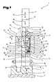
- a folding device 1 for producing a 180 ° Falzbuges on a sheet-shaped workpiece 2 between a fixed bending die 3 and an adjustable bending punch 4 and a seam die 5, a not shown in detail bending press shown.
- the tool holder 7 is adjustable by means of an adjusting device on an upper side of a table beam 9 of the bending press - according to double arrow 10 - superimposed.
- This adjustment is, for example, a hydraulic drive, electric drive, etc. and the adjustment is done, for example, manually against predetermined stops or program controlled by a machine control.
- the bending die 3 has a V-groove 12 for the leading edge of the workpiece at a predetermined angle, for example less than 90 °, at an end face 11 opposite the clamping strip 8.
- the seam die 5 is formed by an L-shaped base body 13 with a base leg 14 and a leg 15 extending parallel to the bending die 3, and is in addition to the attachment to the bending die 3 e.g. Screws 16, supported with a base surface 17 of the base leg 14 on an upper surface 18 of the tool holder 7.
- the extending from the base leg 14 parallel to the bending die and at a distance 19 from the side surface 6 of the bending die 3 legs 15 has a height 20, whereby one of the base surface 17 opposite end face 21 of the leg 15 with the end face 11 of the bending die 3 in a common is aligned to a bending plane 22 vertically extending plane 23.
- FIG. 1 now the position of the bending die 3 is shown with the seam die 5, in which the punch 4 in adjustment according to a - double arrow 24 - with a strip-shaped projection 25 and a projecting wedge extension 26 in a by the distance 19 of the leg 15 of the side surface 6 of Biegegesenks 3 formed gap 27 protrudes.
- a thickness 28 of the strip-shaped projection 25 is slightly smaller than the distance 19.
- the projection 25 and the wedge extension 26 form a common planar side surface 29, which aligned with the smallest gap formation to one of the side surface 6 of the bending die 3 opposite side surface 30 of the leg 15 is.
- a total thickness 31 of a gripping head of the punch 4 is greater than the thickness 28 of the strip-shaped projection 25, whereby a side surface 29 extending in a vertical plane embossing surface 32 is formed on the punch 4, which in a corresponding position of the punch 4 for a final bending of the folding broom on Workpiece 2 cooperates with a support surface 33 formed by the end face 21 of the leg 15.
- a slot-shaped receiving chamber 37 In addition to the immersion slot 36, a slot-shaped receiving chamber 37, widening the immersion slot 36, is incorporated in the leg 15.
- a two-arm lever elements 38 is pivotally mounted in a pivot bearing assembly 39 about a pivot axis 40 in an adjustment plane perpendicular to the side surface 29 of the wedge extension 26, wherein the pivot axis 40, parallel to the base surface 17 of the base body 13 extends.
- a lever arm 41 of the two-arm lever element 38 extends in the immersion slot 36 in the direction of the support surface 33 and a further lever arm 42 in the direction of the base surface 17.
- a slider element 44 In an end region 43 of the lever arm 41 is pivotally connected to a slider element 44 in a guide arrangement 45, formed by both sides of the immersion slit 36 in the leg 15 in the side surface 30 perpendicularly extending guideways 46, 47 is slidably mounted.
- a hinge 48 between the lever arm 41 and the slider member 44 is formed by a bolt 49 between a fork formation of the lever arm 41 and a bearing extension of the slider member 44.
- the articulation 48 ensures an exact linear displacement of the slide element 44 during a pivotal movement of the two-arm lever element 38 in that e.g. the projected by the bolt 49 bearing extension of the slider element 44 has a slot.
- the further lever arm 42 is on an end face 50 facing the base surface 17 via a spring arrangement 51, e.g. Spiral compression spring biased toward the side surface 30 of the leg 15 and has in the end region 50 preferably two adjusting cams 53, 54 which project beyond the side surface 30 of the leg 15 in the biased by the compression coil spring 52 position of the lever arm 42, i. protrude into the gap 27. This position is ensured by a stop surface of the limb 15 for the drive arm 41 connected to the slider element 44.
- a spring arrangement 51 e.g. Spiral compression spring biased toward the side surface 30 of the leg 15 and has in the end region 50 preferably two adjusting cams 53, 54 which project beyond the side surface 30 of the leg 15 in the biased by the compression coil spring 52 position of the lever arm 42, i. protrude into the gap 27. This position is ensured by a stop surface of the limb 15 for the drive arm 41 connected to the slider element 44.
- the arrangement of the adjusting cams 53, 54 on the lever arm 42 is such that a distance 55 between the adjusting cams 53, 54 a passing movement of the Tastusion 35 between the adjusting cam 53, 54, with an adjustment of the wedge extension 26 in the direction of the base surface 17 and dem dem Gap 27 limiting top 56 of the base leg 14 allows.
- the movement element 44 movably connected to the lever arm 41 has a width 57 measured in the adjustment direction, which corresponds approximately to a thickness 58 of the limb 15 minus a projection 59 of the touch disc 35, by which it projects beyond the side surface 29 of the wedge extension 26.
- the slider member 44 In the biased by the compression coil spring 52 position of the two-arm lever member 38, the slider member 44 is in a remote from the side surface 29 of the wedge extension 26 position, whereby the insertion slot 33 is released for passing the feeler disk 35.
- embossed marks on the workpiece 2 are effectively prevented by edges on the immersion slot 36 during final bending of the pre-canted workpiece 2 and production of the 180 ° folding brow. which would otherwise occur when applying the forming force by the punch 4.
- the pre-canted work piece 2 can be placed on the support surface 33 of the seam die 5 during the further adjustment movement of the punch 4, wherein the side surface 29 of the wedge extension 26 forms a contact surface for the workpiece 2.
- Vorkantvorganges now takes place the adjustment of the tool holder 7 on the table bar 9 in the corresponding position for the bending position by a distance 61 in which the bending die 3 with the V-groove 12 and the wedge extension 36 in the bending plane 22 are aligned opposite each other ,
- the position of the wedge extension 26 is shown in the gap 27 between the bending die 3 and the legs 15 of the seam die 5.
- the wedge tip 34 begins to act on the adjusting cams 53, 54 of the lever arm 42 in an adjustment according to - arrow 62 - act.
- One of the wedge tip 34 facing top 63 of the adjusting cams 53, 54 is in the form of a curved link, whereby a sliding emergence and adjustment of the lever arm 42 against the action of the spring assembly 51 to a total projection to which the adjusting cams 53, 54, the side surface 30 of the leg 15 project beyond, is reached.
- a depth 66 of the immersion slit 36 is approximately equal to the height 20 of the leg 15 and is greater than a measured in the vertical direction between the embossing surface 32 and the wedge tip 34 length 67 of the wedge extension 26.
- a vertically measured distance 68 between the support surface 33 and End face 21 of the leg 15 and the adjusting cam 53, 54 is smaller than the length 67 of the wedge extension 26th
- FIG. 6 Another embodiment of the support surface 33 forming the slide member 44 is shown in this is designed as a T-nut 69 and in both sides of the immersion slot 36 and side surfaces of the gap space 37, the guide assembly 45 forming guide grooves 70 are introduced.
- a balance between the linear movement of the slide member 44 and the pivotal movement of the lever arm 41 is achieved.
Landscapes
- Engineering & Computer Science (AREA)
- Mechanical Engineering (AREA)
- Bending Of Plates, Rods, And Pipes (AREA)
Claims (22)
- Dispositif de pliage (1) pour une presse à plier, en particulier une presse-plieuse pour un pli de 180° à réaliser sur une pièce à usiner (2), comportant une matrice de flexion (3) présentant une rainure en V et un poinçon de formage (4), réglable par rapport à celle-ci et présentant un prolongement cunéiforme (26) et comportant une matrice de pliage (5), disposée de manière adjacente à la matrice de flexion (3), formant une surface d'appui (33) sur un plan (23) s'étendant perpendiculairement à un sens de déplacement du poinçon de formage (4) et comportant un porte-outil (7), pour la matrice de flexion (3) et la matrice de pliage (5), qui est disposé de manière mobile sur un côté supérieur (18) d'un montant de table (9) dans un sens perpendiculaire à un plan de flexion (22), caractérisé en ce que, entre des surfaces latérales (6, 30) tournées l'une vers l'autre de la matrice de flexion (3) et de la matrice de pliage (5), un interstice (27) est formé, par un espacement (19) mesuré perpendiculairement au plan de flexion (22), pour le logement du prolongement cunéiforme (26).
- Dispositif de pliage (1) selon la revendication 1, caractérisé en ce qu'on a disposé, dans la matrice de pliage (5), face à l'interstice (27), une fente d'insertion (36) partant de la surface d'appui (33) dans le sens du déplacement du poinçon de formage (4) et en ce qu'on a placé un élément à coulisse (44) de manière à ce qu'il recouvre la fente d'insertion (36) et forme au moins une zone de la surface d'appui (33) avec une superficie, élément à coulisse déplaçable dans un système de guidage (45), de la matrice de pliage (5), s'étendant principalement sur le plan (23).
- Dispositif de pliage (1) selon la revendication 1, caractérisé en ce que la matrice de pliage (5) est formée d'un corps de base (13) sensiblement en forme de L qui est fixé, par un montant de base (14), sur la surface latérale (6) de la matrice de flexion (3) et est étayé de préférence, par une surface de base (17), sur une face supérieure (18) du porte-outil (7).
- Dispositif de pliage (1) selon la revendication 2, caractérisé en ce qu'on a orienté un autre montant (15) du corps de base (13) de manière à ce qu'il s'étende parallèlement et à une distance (19) de la surface latérale (6) de la matrice de flexion (3).
- Dispositif de pliage (1) selon la revendication 1, caractérisé en ce que la distance (19) est légèrement supérieure à l'épaisseur (28) d'un embout (25) destiné au prolongement cunéiforme (26) du poinçon de formage (4).
- Dispositif de pliage (1) selon la revendication 2, caractérisé en ce qu'on a disposé, dans la fente d'insertion (36), un élément à levier à deux bras (38) logé dans un système de palier pivotant (39), élément qui peut être pivoté sur un plan de déplacement s'étendant perpendiculairement au plan de flexion (22), autour d'un axe de pivotement (40) orienté parallèlement à la surface latérale (30) du montant (15).
- Dispositif de pliage (1) selon la revendication 6, caractérisé en ce qu'un bras à levier (41) de l'élément à levier à deux bras (38), saillant de l'axe de pivotement (40) en direction de la surface d'appui (33), est relié à l'élément à coulisse (44) dans une zone d'extrémité (43) par le biais d'une liaison articulée (48).
- Dispositif de pliage (1) selon la revendication 6, caractérisé en ce qu'un autre bras à levier (42) de l'élément à levier à deux bras (38), saillant de l'axe de pivotement (40) en direction du montant de base (14), est pourvu, dans une zone d'extrémité (50), de préférence de deux cames de réglage (53, 54) séparées par une fente.
- Dispositif de pliage (1) selon la revendication 8, caractérisé en ce que le bras à levier (42), présentant les cames de réglage (53, 54) est précontraint, dans la zone d'extrémité (50), par le biais d'un élément à ressort, par exemple du ressort à pression hélicoïdal (52) d'un système de ressort (51) en direction de la matrice de flexion (3).
- Dispositif de pliage (1) selon la revendication 8, caractérisé en ce que, dans une position d'extrémité commandée par ressort, de l'élément à levier à deux bras (38), les cames de réglage (53, 54) dépassent de la surface latérale (30) du montant (15) de la matrice de pliage (5), surface latérale tournée vers la surface latérale (6) de la matrice de flexion (3).
- Dispositif de pliage (1) selon la revendication 9, caractérisé en ce que, dans la position d'extrémité commandée par ressort, de l'élément à levier à deux bras (38), on a positionné l'élément à coulisse (44) dans une position libérant la fente d'insertion (36) après butée contre la traverse de la paroi arrière (64) du montant (15).
- Dispositif de pliage (1) selon la revendication 2, caractérisé en ce que l'élément à coulisse (44) présente une section transversale sensiblement en forme de T.
- Dispositif de pliage (1) selon la revendication 2, caractérisé en ce que l'élément à coulisse (44) est réalisé sous la forme d'un coulisseau (69).
- Dispositif de pliage (1) selon la revendication 2, caractérisé en ce que le système de guidage (45) est formé de glissières (47) s'étendant des deux côtés de la fente d'insertion (36).
- Dispositif de pliage (1) selon la revendication 2, caractérisé en ce que le système de guidage (45) est formé de rainures de guidage (70) s'étendant des deux côtés de la fente d'insertion (70).
- Dispositif de pliage (1) selon la revendication 1, caractérisé en ce que le porte-outil (7) est logé sur le montant de table, avec la matrice de flexion (3) et la matrice de pliage (5), de manière à pouvoir être déplacé par rapport au poinçon de formage (4), d'une distance (61), perpendiculairement au plan de flexion (22), entre une première position alignée du prolongement cunéiforme (26) avec la rainure en V (12) de la matrice de flexion (3) et une seconde position pour un déplacement du prolongement cunéiforme (26) dans l'espace interstitiel (27).
- Dispositif de pliage (1) selon la revendication 1 ou 16, caractérisé en ce qu'une tête de serrage du poinçon de formage (4) présente, sur un plan (23) s'étendant perpendiculairement à une surface latérale plane (29) du prolongement cunéiforme (26), une surface à estamper (33) agissant de concert avec la surface d'appui (33) de la matrice de pliage (5).
- Dispositif de pliage (1) selon la revendication 17, caractérisé en ce qu'une longueur (67), mesurée de la surface à estamper (32) à une pointe cunéiforme (34) du prolongement cunéiforme (26), est inférieure à une hauteur (20) du montant (15) du corps de base (13) ou une profondeur (66) d'un espace interstitiel (27), entre le poinçon de formage (4) et le montant (15) du corps de base (13).
- Dispositif de pliage (1) selon la revendication 18, caractérisé en ce que la longueur (67) du prolongement cunéiforme (26) est supérieure à une distance (68) des cames de réglage (53, 54) mesurée à partir de la surface d'appui (33).
- Dispositif de pliage (1) selon la revendication 8, caractérisé en ce qu'une face supérieure (63) des cames de réglage (53, 54), tournée vers le prolongement cunéiforme (26), est réalisée avec une courbure.
- Dispositif de pliage (1) selon la revendication 8 ou 20, caractérisé en ce qu'une saillie des cames de réglage (53, 54), dépassant de la surface latérale (30) du montant (15), est inférieure à une trajectoire de déplacement du bras à levier (42) comportant les cames de réglage (53, 54).
- Dispositif de pliage (1) selon la revendication 2, caractérisé en ce qu'une traverse de la paroi arrière (64) du montant (15), délimitant la chambre de logement (37), forme une butée pour l'élément à coulisse (44) dans une position située à distance de la matrice de flexion (3).
Applications Claiming Priority (1)
| Application Number | Priority Date | Filing Date | Title |
|---|---|---|---|
| AT0026708A AT505656B1 (de) | 2008-02-19 | 2008-02-19 | Falzvorrichtung für eine biegepresse, insbesondere abkantpresse |
Publications (3)
| Publication Number | Publication Date |
|---|---|
| EP2092992A2 EP2092992A2 (fr) | 2009-08-26 |
| EP2092992A3 EP2092992A3 (fr) | 2011-06-08 |
| EP2092992B1 true EP2092992B1 (fr) | 2012-07-18 |
Family
ID=40427626
Family Applications (1)
| Application Number | Title | Priority Date | Filing Date |
|---|---|---|---|
| EP09002334A Not-in-force EP2092992B1 (fr) | 2008-02-19 | 2009-02-19 | Dispositif de pliage pour une presse à plier, notamment presse plieuse |
Country Status (3)
| Country | Link |
|---|---|
| US (1) | US7997115B2 (fr) |
| EP (1) | EP2092992B1 (fr) |
| AT (1) | AT505656B1 (fr) |
Families Citing this family (23)
| Publication number | Priority date | Publication date | Assignee | Title |
|---|---|---|---|---|
| KR20140022386A (ko) | 2011-04-18 | 2014-02-24 | 파이프 컴파니, 엘.엘.씨. | 기존 파이프의 보호 및 강화용 팽창성 라이너 |
| US20120324977A1 (en) * | 2011-06-22 | 2012-12-27 | Wu yong-ping | Stamping tool |
| AT511621B1 (de) | 2011-07-01 | 2013-04-15 | Trumpf Maschinen Austria Gmbh | Falzvorrichtung für eine biegepresse und verfahren zur durchführung einer falzung |
| AT513741B1 (de) | 2013-03-28 | 2014-07-15 | Trumpf Maschinen Austria Gmbh | Biegewerkzeuge zum Vorbiegen und Zudrücken |
| CN104998934B (zh) * | 2014-04-08 | 2017-03-22 | 安徽新源精密模具有限公司 | 一种九折工件的加工方法 |
| AU2015275790A1 (en) | 2014-06-16 | 2016-12-01 | Fyfe Co. Llc | Repair of pipes |
| CA2897301C (fr) | 2014-07-14 | 2020-06-02 | Fyfe Co. Llc | Revetement de tuyau etanche et tres resistant |
| CN104722612B (zh) * | 2015-03-16 | 2016-09-14 | 上海元阳金属制品有限公司 | 折弯机上模折弯间隙调整装置及间隙调整方法 |
| US9993992B2 (en) | 2015-04-17 | 2018-06-12 | Fyfe Co. Llc | Structural fabric useful for lining pipe |
| US10077855B2 (en) | 2015-09-22 | 2018-09-18 | Ina Acquisition Corp. | Method of lining pipe with high strength liner, high strength liner, and pipe lined with high strength liner |
| US11173634B2 (en) | 2018-02-01 | 2021-11-16 | Ina Acquisition Corp | Electromagnetic radiation curable pipe liner and method of making and installing the same |
| US10704728B2 (en) | 2018-03-20 | 2020-07-07 | Ina Acquisition Corp. | Pipe liner and method of making same |
| CN108580773B (zh) * | 2018-06-09 | 2023-05-16 | 江苏华威机械制造有限公司 | 一种液压重锤锻造机及其智能控制方法 |
| CN109226494B (zh) * | 2018-10-31 | 2024-02-06 | 凌云西南工业有限公司 | 一种汽车保险杠配件级进模 |
| CN109821974B (zh) * | 2019-03-22 | 2024-05-07 | 山东小鸭精工机械有限公司 | 卧式扩张机 |
| CN110695229B (zh) * | 2019-10-16 | 2024-08-06 | 一汽奔腾轿车有限公司 | 一种冲压拉延模具定位结构 |
| CN111803305B (zh) * | 2020-08-11 | 2024-11-05 | 烟台宏远载人压力舱工程技术研究院有限公司 | 一种压力舱楔紧式预紧舱门 |
| CN112058980A (zh) * | 2020-09-25 | 2020-12-11 | 安徽鲲鹏装备模具制造有限公司 | 一种宽度自动无级调整的端折弯设备 |
| JP7486441B2 (ja) * | 2021-01-20 | 2024-05-17 | 株式会社アマダ | 折曲げ加工方法 |
| CN113915458B (zh) * | 2021-11-02 | 2023-04-18 | 英索来欣(苏州)新材料科技有限公司 | 一种真空绝热板芯材 |
| CN114226557B (zh) * | 2021-12-17 | 2024-02-23 | 江苏泽恩汽机车部品制造有限公司 | 一种基于汽车支架冲压模具的侧推折弯机构 |
| CN115193964B (zh) * | 2022-07-08 | 2023-08-01 | 江苏富茹电子科技集团有限公司 | 一种变压器铁芯上夹件冲压成型装置 |
| CN118403946B (zh) * | 2024-07-01 | 2024-10-18 | 吉林省德立智能科技有限公司 | 一种汽车制造的横梁成型机构 |
Family Cites Families (13)
| Publication number | Priority date | Publication date | Assignee | Title |
|---|---|---|---|---|
| AT293823B (de) * | 1969-09-22 | 1971-10-25 | Haemmerle Ag Maschf | Biegebearbeitungseinrichtung |
| US3845655A (en) * | 1972-09-18 | 1974-11-05 | Widder Corp | Press brakes |
| DE2652886A1 (de) * | 1976-11-20 | 1978-05-24 | Weinbrenner Paul Maschbau | Biegebearbeitungseinrichtung |
| CH655874A5 (de) * | 1982-06-07 | 1986-05-30 | Haemmerle Ag Maschf | Werkzeugeinrichtung an einer abkantpresse. |
| JPS61176422A (ja) * | 1985-01-30 | 1986-08-08 | Natl House Ind Co Ltd | 曲げ加工装置 |
| US4691553A (en) * | 1986-03-06 | 1987-09-08 | Barber Stephen C | Safety power tool |
| US4805438A (en) * | 1987-03-05 | 1989-02-21 | Metal Building Components Incorporated | Hemming die fixture for metal presses |
| US4852379A (en) * | 1988-07-15 | 1989-08-01 | Nat Levenberg | Metal forming methods and products formed thereby |
| EP0624411A1 (fr) * | 1993-05-13 | 1994-11-17 | Hämmerle Ag | Procédé pour plier des tôles et presse à plier pour la mise en oeuvre du procédé |
| DE4315706C2 (de) * | 1993-05-13 | 1996-02-01 | Haemmerle Ag | Abkantpressen zur Bildung von Falznuten an Blechprofilen |
| DE4425992C2 (de) * | 1994-07-22 | 1996-11-28 | Roland Man Druckmasch | Maschinenverkleidung für eine Druckmaschine |
| JPH10137852A (ja) * | 1996-11-11 | 1998-05-26 | Murai Kogyo Kk | 折り曲げ、平押し金型 |
| JP4219458B2 (ja) * | 1998-12-18 | 2009-02-04 | 株式会社アマダ | 曲げ加工装置 |
-
2008
- 2008-02-19 AT AT0026708A patent/AT505656B1/de not_active IP Right Cessation
-
2009
- 2009-02-18 US US12/388,279 patent/US7997115B2/en not_active Expired - Fee Related
- 2009-02-19 EP EP09002334A patent/EP2092992B1/fr not_active Not-in-force
Also Published As
| Publication number | Publication date |
|---|---|
| EP2092992A2 (fr) | 2009-08-26 |
| US20100018283A1 (en) | 2010-01-28 |
| AT505656B1 (de) | 2009-03-15 |
| AT505656A4 (de) | 2009-03-15 |
| EP2092992A3 (fr) | 2011-06-08 |
| US7997115B2 (en) | 2011-08-16 |
Similar Documents
| Publication | Publication Date | Title |
|---|---|---|
| EP2092992B1 (fr) | Dispositif de pliage pour une presse à plier, notamment presse plieuse | |
| DE69403932T2 (de) | Bearbeitungsstation mit Stümpfpositionierung und Laserstrahlschweissen von zwei Blechkanten | |
| EP2107650B1 (fr) | Pince de serrage dotée d'un positionneur | |
| AT503790B1 (de) | Anschlagvorrichtung für eine biegepresse | |
| EP0022122A1 (fr) | Machine de cintrage | |
| DE7718218U1 (de) | Schnittwerkzeugsatz zum schneiden laenglicher werkstuecke | |
| DE3587327T2 (de) | Abkantpresse. | |
| EP1561546B1 (fr) | Dispositif de serrage | |
| EP1622731B1 (fr) | Dispositif porte-outil | |
| EP1810761B1 (fr) | Dispositif de pliage de tôles | |
| AT507808B1 (de) | Biegepresse mit einem antriebsbalken und elastisch gekuppelten biegebalken | |
| DE3308219C2 (de) | Maschine zum Profilieren von Blechen für die Herstellung von Falzen | |
| DE19507286C2 (de) | Abrichtlinealführung für motorbetriebene Werkzeuge | |
| DE10240849B4 (de) | Biegematrize in einem Heftapparat | |
| WO1991006383A1 (fr) | Procede de cintrage oppose d'une tole | |
| DE4315706C2 (de) | Abkantpressen zur Bildung von Falznuten an Blechprofilen | |
| DE2510884B2 (de) | Vorrichtung zum verbinden von zwei auf gehrung geschnittenen metallprofilstaeben | |
| EP1377395B1 (fr) | Machine de pliage, en particulier presse a estamper ou a plier, pourvue d'un outil inferieur reglable | |
| DE102010004836B4 (de) | Vorrichtung zur Erzeugung eines Bogens | |
| DE2805206C2 (de) | Abbiegewerkzeug zum Herstellen U-förmiger Werkstücke | |
| DE3120514C2 (de) | Falzschließmaschine | |
| DE202013004278U1 (de) | Vorrichtung zum Verbinden von Blechschalen zu einem Gehäuse eines Werkstücks mittels Falzen an Rändern der Blechschalen | |
| DE4030777A1 (de) | Abkantpressen-system mit einer richteinrichtung fuer plattenfoermige werkstuecke | |
| EP2726227B1 (fr) | Presse à cintrer avec un dispositif de pliage et procédé de pliage | |
| DE820291C (de) | Maschine zum Abbiegen von Blechen |
Legal Events
| Date | Code | Title | Description |
|---|---|---|---|
| PUAI | Public reference made under article 153(3) epc to a published international application that has entered the european phase |
Free format text: ORIGINAL CODE: 0009012 |
|
| AK | Designated contracting states |
Kind code of ref document: A2 Designated state(s): AT BE BG CH CY CZ DE DK EE ES FI FR GB GR HR HU IE IS IT LI LT LU LV MC MK MT NL NO PL PT RO SE SI SK TR |
|
| AX | Request for extension of the european patent |
Extension state: AL BA RS |
|
| PUAL | Search report despatched |
Free format text: ORIGINAL CODE: 0009013 |
|
| AK | Designated contracting states |
Kind code of ref document: A3 Designated state(s): AT BE BG CH CY CZ DE DK EE ES FI FR GB GR HR HU IE IS IT LI LT LU LV MC MK MT NL NO PL PT RO SE SI SK TR |
|
| AX | Request for extension of the european patent |
Extension state: AL BA RS |
|
| GRAP | Despatch of communication of intention to grant a patent |
Free format text: ORIGINAL CODE: EPIDOSNIGR1 |
|
| 17P | Request for examination filed |
Effective date: 20111207 |
|
| AKX | Designation fees paid |
Designated state(s): AT BE BG CH CY CZ DE DK EE ES FI FR GB GR HR HU IE IS IT LI LT LU LV MC MK MT NL NO PL PT RO SE SI SK TR |
|
| GRAS | Grant fee paid |
Free format text: ORIGINAL CODE: EPIDOSNIGR3 |
|
| GRAA | (expected) grant |
Free format text: ORIGINAL CODE: 0009210 |
|
| AK | Designated contracting states |
Kind code of ref document: B1 Designated state(s): AT BE BG CH CY CZ DE DK EE ES FI FR GB GR HR HU IE IS IT LI LT LU LV MC MK MT NL NO PL PT RO SE SI SK TR |
|
| REG | Reference to a national code |
Ref country code: GB Ref legal event code: FG4D Free format text: NOT ENGLISH |
|
| REG | Reference to a national code |
Ref country code: CH Ref legal event code: EP |
|
| REG | Reference to a national code |
Ref country code: AT Ref legal event code: REF Ref document number: 566822 Country of ref document: AT Kind code of ref document: T Effective date: 20120815 Ref country code: IE Ref legal event code: FG4D Free format text: LANGUAGE OF EP DOCUMENT: GERMAN |
|
| REG | Reference to a national code |
Ref country code: CH Ref legal event code: NV Representative=s name: ABP PATENT NETWORK SWISS GMBH |
|
| REG | Reference to a national code |
Ref country code: DE Ref legal event code: R096 Ref document number: 502009004105 Country of ref document: DE Effective date: 20120913 |
|
| REG | Reference to a national code |
Ref country code: NL Ref legal event code: T3 |
|
| REG | Reference to a national code |
Ref country code: LT Ref legal event code: MG4D Effective date: 20120718 |
|
| PG25 | Lapsed in a contracting state [announced via postgrant information from national office to epo] |
Ref country code: FI Free format text: LAPSE BECAUSE OF FAILURE TO SUBMIT A TRANSLATION OF THE DESCRIPTION OR TO PAY THE FEE WITHIN THE PRESCRIBED TIME-LIMIT Effective date: 20120718 Ref country code: IS Free format text: LAPSE BECAUSE OF FAILURE TO SUBMIT A TRANSLATION OF THE DESCRIPTION OR TO PAY THE FEE WITHIN THE PRESCRIBED TIME-LIMIT Effective date: 20121118 Ref country code: CY Free format text: LAPSE BECAUSE OF FAILURE TO SUBMIT A TRANSLATION OF THE DESCRIPTION OR TO PAY THE FEE WITHIN THE PRESCRIBED TIME-LIMIT Effective date: 20120718 Ref country code: NO Free format text: LAPSE BECAUSE OF FAILURE TO SUBMIT A TRANSLATION OF THE DESCRIPTION OR TO PAY THE FEE WITHIN THE PRESCRIBED TIME-LIMIT Effective date: 20121018 Ref country code: HR Free format text: LAPSE BECAUSE OF FAILURE TO SUBMIT A TRANSLATION OF THE DESCRIPTION OR TO PAY THE FEE WITHIN THE PRESCRIBED TIME-LIMIT Effective date: 20120718 Ref country code: LT Free format text: LAPSE BECAUSE OF FAILURE TO SUBMIT A TRANSLATION OF THE DESCRIPTION OR TO PAY THE FEE WITHIN THE PRESCRIBED TIME-LIMIT Effective date: 20120718 |
|
| PG25 | Lapsed in a contracting state [announced via postgrant information from national office to epo] |
Ref country code: SI Free format text: LAPSE BECAUSE OF FAILURE TO SUBMIT A TRANSLATION OF THE DESCRIPTION OR TO PAY THE FEE WITHIN THE PRESCRIBED TIME-LIMIT Effective date: 20120718 Ref country code: LV Free format text: LAPSE BECAUSE OF FAILURE TO SUBMIT A TRANSLATION OF THE DESCRIPTION OR TO PAY THE FEE WITHIN THE PRESCRIBED TIME-LIMIT Effective date: 20120718 Ref country code: SE Free format text: LAPSE BECAUSE OF FAILURE TO SUBMIT A TRANSLATION OF THE DESCRIPTION OR TO PAY THE FEE WITHIN THE PRESCRIBED TIME-LIMIT Effective date: 20120718 Ref country code: PL Free format text: LAPSE BECAUSE OF FAILURE TO SUBMIT A TRANSLATION OF THE DESCRIPTION OR TO PAY THE FEE WITHIN THE PRESCRIBED TIME-LIMIT Effective date: 20120718 Ref country code: PT Free format text: LAPSE BECAUSE OF FAILURE TO SUBMIT A TRANSLATION OF THE DESCRIPTION OR TO PAY THE FEE WITHIN THE PRESCRIBED TIME-LIMIT Effective date: 20121119 Ref country code: GR Free format text: LAPSE BECAUSE OF FAILURE TO SUBMIT A TRANSLATION OF THE DESCRIPTION OR TO PAY THE FEE WITHIN THE PRESCRIBED TIME-LIMIT Effective date: 20121019 |
|
| PG25 | Lapsed in a contracting state [announced via postgrant information from national office to epo] |
Ref country code: CZ Free format text: LAPSE BECAUSE OF FAILURE TO SUBMIT A TRANSLATION OF THE DESCRIPTION OR TO PAY THE FEE WITHIN THE PRESCRIBED TIME-LIMIT Effective date: 20120718 Ref country code: EE Free format text: LAPSE BECAUSE OF FAILURE TO SUBMIT A TRANSLATION OF THE DESCRIPTION OR TO PAY THE FEE WITHIN THE PRESCRIBED TIME-LIMIT Effective date: 20120718 Ref country code: ES Free format text: LAPSE BECAUSE OF FAILURE TO SUBMIT A TRANSLATION OF THE DESCRIPTION OR TO PAY THE FEE WITHIN THE PRESCRIBED TIME-LIMIT Effective date: 20121029 Ref country code: RO Free format text: LAPSE BECAUSE OF FAILURE TO SUBMIT A TRANSLATION OF THE DESCRIPTION OR TO PAY THE FEE WITHIN THE PRESCRIBED TIME-LIMIT Effective date: 20120718 Ref country code: DK Free format text: LAPSE BECAUSE OF FAILURE TO SUBMIT A TRANSLATION OF THE DESCRIPTION OR TO PAY THE FEE WITHIN THE PRESCRIBED TIME-LIMIT Effective date: 20120718 |
|
| PLBE | No opposition filed within time limit |
Free format text: ORIGINAL CODE: 0009261 |
|
| STAA | Information on the status of an ep patent application or granted ep patent |
Free format text: STATUS: NO OPPOSITION FILED WITHIN TIME LIMIT |
|
| PG25 | Lapsed in a contracting state [announced via postgrant information from national office to epo] |
Ref country code: SK Free format text: LAPSE BECAUSE OF FAILURE TO SUBMIT A TRANSLATION OF THE DESCRIPTION OR TO PAY THE FEE WITHIN THE PRESCRIBED TIME-LIMIT Effective date: 20120718 |
|
| 26N | No opposition filed |
Effective date: 20130419 |
|
| PG25 | Lapsed in a contracting state [announced via postgrant information from national office to epo] |
Ref country code: BG Free format text: LAPSE BECAUSE OF FAILURE TO SUBMIT A TRANSLATION OF THE DESCRIPTION OR TO PAY THE FEE WITHIN THE PRESCRIBED TIME-LIMIT Effective date: 20121018 |
|
| REG | Reference to a national code |
Ref country code: DE Ref legal event code: R097 Ref document number: 502009004105 Country of ref document: DE Effective date: 20130419 |
|
| REG | Reference to a national code |
Ref country code: CH Ref legal event code: NV Representative=s name: ABP PATENT NETWORK AG, CH |
|
| BERE | Be: lapsed |
Owner name: TRUMPF MASCHINEN AUSTRIA GMBH & CO. KG. Effective date: 20130228 |
|
| PG25 | Lapsed in a contracting state [announced via postgrant information from national office to epo] |
Ref country code: MC Free format text: LAPSE BECAUSE OF NON-PAYMENT OF DUE FEES Effective date: 20130228 |
|
| GBPC | Gb: european patent ceased through non-payment of renewal fee |
Effective date: 20130219 |
|
| REG | Reference to a national code |
Ref country code: IE Ref legal event code: MM4A |
|
| PG25 | Lapsed in a contracting state [announced via postgrant information from national office to epo] |
Ref country code: GB Free format text: LAPSE BECAUSE OF NON-PAYMENT OF DUE FEES Effective date: 20130219 Ref country code: IE Free format text: LAPSE BECAUSE OF NON-PAYMENT OF DUE FEES Effective date: 20130219 Ref country code: BE Free format text: LAPSE BECAUSE OF NON-PAYMENT OF DUE FEES Effective date: 20130228 |
|
| PG25 | Lapsed in a contracting state [announced via postgrant information from national office to epo] |
Ref country code: MT Free format text: LAPSE BECAUSE OF FAILURE TO SUBMIT A TRANSLATION OF THE DESCRIPTION OR TO PAY THE FEE WITHIN THE PRESCRIBED TIME-LIMIT Effective date: 20120718 |
|
| PG25 | Lapsed in a contracting state [announced via postgrant information from national office to epo] |
Ref country code: TR Free format text: LAPSE BECAUSE OF FAILURE TO SUBMIT A TRANSLATION OF THE DESCRIPTION OR TO PAY THE FEE WITHIN THE PRESCRIBED TIME-LIMIT Effective date: 20120718 |
|
| PG25 | Lapsed in a contracting state [announced via postgrant information from national office to epo] |
Ref country code: MK Free format text: LAPSE BECAUSE OF FAILURE TO SUBMIT A TRANSLATION OF THE DESCRIPTION OR TO PAY THE FEE WITHIN THE PRESCRIBED TIME-LIMIT Effective date: 20120718 Ref country code: HU Free format text: LAPSE BECAUSE OF FAILURE TO SUBMIT A TRANSLATION OF THE DESCRIPTION OR TO PAY THE FEE WITHIN THE PRESCRIBED TIME-LIMIT; INVALID AB INITIO Effective date: 20090219 Ref country code: LU Free format text: LAPSE BECAUSE OF NON-PAYMENT OF DUE FEES Effective date: 20130219 |
|
| REG | Reference to a national code |
Ref country code: FR Ref legal event code: PLFP Year of fee payment: 8 |
|
| REG | Reference to a national code |
Ref country code: CH Ref legal event code: PCAR Free format text: NEW ADDRESS: OTHMARSTRASSE 8, 8008 ZUERICH (CH) |
|
| REG | Reference to a national code |
Ref country code: FR Ref legal event code: PLFP Year of fee payment: 9 |
|
| REG | Reference to a national code |
Ref country code: FR Ref legal event code: PLFP Year of fee payment: 10 |
|
| REG | Reference to a national code |
Ref country code: DE Ref legal event code: R082 Ref document number: 502009004105 Country of ref document: DE Representative=s name: ABP BURGER RECHTSANWALTSGESELLSCHAFT MBH, DE |
|
| PGFP | Annual fee paid to national office [announced via postgrant information from national office to epo] |
Ref country code: FR Payment date: 20190122 Year of fee payment: 11 Ref country code: CH Payment date: 20190211 Year of fee payment: 11 Ref country code: FR Payment date: 20190109 Year of fee payment: 11 |
|
| PGFP | Annual fee paid to national office [announced via postgrant information from national office to epo] |
Ref country code: AT Payment date: 20200130 Year of fee payment: 12 |
|
| REG | Reference to a national code |
Ref country code: CH Ref legal event code: PL |
|
| REG | Reference to a national code |
Ref country code: NL Ref legal event code: MM Effective date: 20200301 |
|
| PG25 | Lapsed in a contracting state [announced via postgrant information from national office to epo] |
Ref country code: LI Free format text: LAPSE BECAUSE OF NON-PAYMENT OF DUE FEES Effective date: 20200229 Ref country code: CH Free format text: LAPSE BECAUSE OF NON-PAYMENT OF DUE FEES Effective date: 20200229 |
|
| PG25 | Lapsed in a contracting state [announced via postgrant information from national office to epo] |
Ref country code: NL Free format text: LAPSE BECAUSE OF NON-PAYMENT OF DUE FEES Effective date: 20200301 |
|
| PG25 | Lapsed in a contracting state [announced via postgrant information from national office to epo] |
Ref country code: FR Free format text: LAPSE BECAUSE OF NON-PAYMENT OF DUE FEES Effective date: 20200229 |
|
| REG | Reference to a national code |
Ref country code: AT Ref legal event code: MM01 Ref document number: 566822 Country of ref document: AT Kind code of ref document: T Effective date: 20210219 |
|
| PG25 | Lapsed in a contracting state [announced via postgrant information from national office to epo] |
Ref country code: AT Free format text: LAPSE BECAUSE OF NON-PAYMENT OF DUE FEES Effective date: 20210219 |
|
| PGFP | Annual fee paid to national office [announced via postgrant information from national office to epo] |
Ref country code: DE Payment date: 20211213 Year of fee payment: 14 |
|
| PGFP | Annual fee paid to national office [announced via postgrant information from national office to epo] |
Ref country code: IT Payment date: 20220203 Year of fee payment: 14 |
|
| REG | Reference to a national code |
Ref country code: DE Ref legal event code: R119 Ref document number: 502009004105 Country of ref document: DE |
|
| PG25 | Lapsed in a contracting state [announced via postgrant information from national office to epo] |
Ref country code: IT Free format text: LAPSE BECAUSE OF NON-PAYMENT OF DUE FEES Effective date: 20230219 Ref country code: DE Free format text: LAPSE BECAUSE OF NON-PAYMENT OF DUE FEES Effective date: 20230901 |